EP0061940B1 - Système de mesure de pression différentielle - Google Patents
Système de mesure de pression différentielle Download PDFInfo
- Publication number
- EP0061940B1 EP0061940B1 EP82400192A EP82400192A EP0061940B1 EP 0061940 B1 EP0061940 B1 EP 0061940B1 EP 82400192 A EP82400192 A EP 82400192A EP 82400192 A EP82400192 A EP 82400192A EP 0061940 B1 EP0061940 B1 EP 0061940B1
- Authority
- EP
- European Patent Office
- Prior art keywords
- pressure
- signal
- alternating
- feedback
- digital
- Prior art date
- Legal status (The legal status is an assumption and is not a legal conclusion. Google has not performed a legal analysis and makes no representation as to the accuracy of the status listed.)
- Expired
Links
- 239000003990 capacitor Substances 0.000 claims description 70
- 239000002775 capsule Substances 0.000 claims description 50
- 230000005284 excitation Effects 0.000 claims description 35
- 229910052774 Proactinium Inorganic materials 0.000 claims description 5
- 229910052745 lead Inorganic materials 0.000 claims description 5
- 230000004044 response Effects 0.000 claims description 5
- 230000006870 function Effects 0.000 description 14
- 230000008859 change Effects 0.000 description 9
- 239000007789 gas Substances 0.000 description 9
- 238000000034 method Methods 0.000 description 9
- 238000009530 blood pressure measurement Methods 0.000 description 7
- 239000010453 quartz Substances 0.000 description 7
- VYPSYNLAJGMNEJ-UHFFFAOYSA-N silicon dioxide Inorganic materials O=[Si]=O VYPSYNLAJGMNEJ-UHFFFAOYSA-N 0.000 description 7
- 239000000446 fuel Substances 0.000 description 5
- 230000010354 integration Effects 0.000 description 5
- 239000000463 material Substances 0.000 description 5
- 238000005259 measurement Methods 0.000 description 5
- 238000006243 chemical reaction Methods 0.000 description 4
- 238000012546 transfer Methods 0.000 description 4
- 230000015572 biosynthetic process Effects 0.000 description 3
- 238000010586 diagram Methods 0.000 description 3
- 238000013507 mapping Methods 0.000 description 3
- 230000003321 amplification Effects 0.000 description 2
- 238000002485 combustion reaction Methods 0.000 description 2
- 239000000203 mixture Substances 0.000 description 2
- 238000003199 nucleic acid amplification method Methods 0.000 description 2
- 230000008569 process Effects 0.000 description 2
- 238000012216 screening Methods 0.000 description 2
- 238000012360 testing method Methods 0.000 description 2
- 230000026683 transduction Effects 0.000 description 2
- 238000010361 transduction Methods 0.000 description 2
- RYGMFSIKBFXOCR-UHFFFAOYSA-N Copper Chemical compound [Cu] RYGMFSIKBFXOCR-UHFFFAOYSA-N 0.000 description 1
- BQCADISMDOOEFD-UHFFFAOYSA-N Silver Chemical compound [Ag] BQCADISMDOOEFD-UHFFFAOYSA-N 0.000 description 1
- 239000004020 conductor Substances 0.000 description 1
- 229910052802 copper Inorganic materials 0.000 description 1
- 239000010949 copper Substances 0.000 description 1
- 238000000354 decomposition reaction Methods 0.000 description 1
- 230000003247 decreasing effect Effects 0.000 description 1
- 230000009977 dual effect Effects 0.000 description 1
- 230000000694 effects Effects 0.000 description 1
- 230000005684 electric field Effects 0.000 description 1
- 239000012530 fluid Substances 0.000 description 1
- PCHJSUWPFVWCPO-UHFFFAOYSA-N gold Chemical compound [Au] PCHJSUWPFVWCPO-UHFFFAOYSA-N 0.000 description 1
- 229910052737 gold Inorganic materials 0.000 description 1
- 239000010931 gold Substances 0.000 description 1
- 239000011810 insulating material Substances 0.000 description 1
- 230000009191 jumping Effects 0.000 description 1
- 239000011159 matrix material Substances 0.000 description 1
- 239000010705 motor oil Substances 0.000 description 1
- 239000013618 particulate matter Substances 0.000 description 1
- 230000002093 peripheral effect Effects 0.000 description 1
- 230000010363 phase shift Effects 0.000 description 1
- 230000000717 retained effect Effects 0.000 description 1
- 230000011664 signaling Effects 0.000 description 1
- 229910052709 silver Inorganic materials 0.000 description 1
- 239000004332 silver Substances 0.000 description 1
- 230000003068 static effect Effects 0.000 description 1
- 238000005019 vapor deposition process Methods 0.000 description 1
- XLYOFNOQVPJJNP-UHFFFAOYSA-N water Chemical compound O XLYOFNOQVPJJNP-UHFFFAOYSA-N 0.000 description 1
- 238000004804 winding Methods 0.000 description 1
Images

Classifications
-
- G—PHYSICS
- G01—MEASURING; TESTING
- G01L—MEASURING FORCE, STRESS, TORQUE, WORK, MECHANICAL POWER, MECHANICAL EFFICIENCY, OR FLUID PRESSURE
- G01L13/00—Devices or apparatus for measuring differences of two or more fluid pressure values
- G01L13/02—Devices or apparatus for measuring differences of two or more fluid pressure values using elastically-deformable members or pistons as sensing elements
- G01L13/028—Devices or apparatus for measuring differences of two or more fluid pressure values using elastically-deformable members or pistons as sensing elements using capsules
-
- G—PHYSICS
- G01—MEASURING; TESTING
- G01L—MEASURING FORCE, STRESS, TORQUE, WORK, MECHANICAL POWER, MECHANICAL EFFICIENCY, OR FLUID PRESSURE
- G01L9/00—Measuring steady of quasi-steady pressure of fluid or fluent solid material by electric or magnetic pressure-sensitive elements; Transmitting or indicating the displacement of mechanical pressure-sensitive elements, used to measure the steady or quasi-steady pressure of a fluid or fluent solid material, by electric or magnetic means
- G01L9/0082—Transmitting or indicating the displacement of capsules by electric, electromechanical, magnetic, or electromechanical means
- G01L9/0086—Transmitting or indicating the displacement of capsules by electric, electromechanical, magnetic, or electromechanical means using variations in capacitance
-
- G—PHYSICS
- G01—MEASURING; TESTING
- G01L—MEASURING FORCE, STRESS, TORQUE, WORK, MECHANICAL POWER, MECHANICAL EFFICIENCY, OR FLUID PRESSURE
- G01L9/00—Measuring steady of quasi-steady pressure of fluid or fluent solid material by electric or magnetic pressure-sensitive elements; Transmitting or indicating the displacement of mechanical pressure-sensitive elements, used to measure the steady or quasi-steady pressure of a fluid or fluent solid material, by electric or magnetic means
- G01L9/12—Measuring steady of quasi-steady pressure of fluid or fluent solid material by electric or magnetic pressure-sensitive elements; Transmitting or indicating the displacement of mechanical pressure-sensitive elements, used to measure the steady or quasi-steady pressure of a fluid or fluent solid material, by electric or magnetic means by making use of variations in capacitance, i.e. electric circuits therefor
Definitions
- This invention relates to a differential pressure measuring system.
- pressure transducer systems In the field of pressure measurement there are many devices known to provide an advantageous transduction of pressure into an electrical signal.
- These pressure transducer systems generally include a 'pressure sensitive element that modulates an electrical characteristic of the transducer with respect to changes in pressure.
- the variances in the electrical characteristic which, for example, may be a resistance, inductance, capacitance, or a similar parameter, are thereafter demodulated by an electrical circuit to generate an electrical signal as a function of the measured pressure.
- the referenced application discloses a highly accurate pressure measuring system which incorporates a closed loop feedback system and yields a digital output.
- the previously developed system comprises a pressure sensitive capacitor and a stable reference capacitor contained within an absolute pressure sensing transducer capsule.
- the pressure sensitive capacitor and reference capacitor are excited by'sinusoidal signals 180° ' out of phase with each other.
- the outputs of the capsule are connected to a summing junction thereby producing a differential signal which is proportional to changes in the measured pressure.
- the summing junction generates an error signal which is amplified and processed by appropriate filters and an integrator to provide an output which excites a similar feedback transducer capsule in a negative feedback loop.
- the outputs of the feedback capsule are combined together and applied to another input of the summing junction.
- the combined output signal from the feedback capsule is utilized to null or balance the differential signal and is thus a measure of the pressure sensed when the summing junction output is zero.
- the feedback loop includes a digital counter for the direct measurement of the number of the discrete increments of feedback signal necessary to null the output of the summing junction.
- the digital readout of the counter is thereby directly proportional to the desired pressure measurement. This system is quite advantageous in the measurement of a single absolute pressure.
- differential pressure transducers have been used in some instances. These transducers generally have two separate chambers each fed by one of the pressures to be differenced. One chamber communicates with one side of a pressure sensitive element of a transducer and the other chamber communicates with the opposite side.
- the pressure sensitive element generally of the diaphragm type, differences the pressures mechanically by deflecting proportionally to each pressure and introduces substantially no error into the measurement. The variances of the electrical characteristic of the pressure sensitive element produced by the deflection is thus a function of the pressure difference.
- differential pressure sensors are not particularly advantageous however, for the control of gas turbine engines where the pressures to be measured are generally from contaminating sources. Many times the fluids whose pressures must be measured are very hot or cold, and may have entrained therein water vapor, droplets of engine oil, or other corrosive particulate matter.
- the present invention in a first aspect, overcomes the limitations and disadvantages of the prior art arrangements by providing a differential pressure measuring system comprising: a first absolute pressure sensing capsule exposed to a first pressure (Pa) and including a first pressure sensitive capacitor (Csa) driven by a first alternating excitation signal (Vr); a second absolute pressure sensing capsule exposed to a second pressure (Pb) and including a second pressure sensitive capacitor (Csb) driven by a second alternating excitation signal (-Vr) 180° out of phase with said first excitation signal (Vr), the output signals from said pressure sensitive capacitors (Csa, Csb) being applied to a summing junction which provides in response thereto an error signal (le); means for providing from said error signal (le) an alternating feedback signal (-Vrf(N)) of the same phase as one of said excitation signals (Vr, -Vr); said alternating feedback signal (-Vrf(N)) being applied to said summing junction via a feedback capacitor (Cf) to nu
- a differential pressure measuring system comprising: a first absolute sensing capsule exposed to .a first pressure (Pa) and including a first pressure sensitive capacitor (Csa) driven by a first alternating excitation signal (Vr); a second absolute pressure sensing capsule exposed to a second pressure (Pb) and including a second pressure sensitive capacitor (Csb) driven by a second alternating excitation signal (-Vr) 180° out of phase with said first excitation signal (Vr), the output signals from said pressure sensitive capacitors (Csa, Csb) being applied to a summing junction which provides in response thereto an error signal (le); means for providing from said error signal (le) an alternating feedback signal (-Vrf(N)) of the same phase as one of said excitation (Vr, -Vr); a feedback absolute pressure sensing capsule exposed to said first pressure (Pa) and including a pressure sensitive capacitor (Csf) driven by said alternating feedback signal (-Vrf(N)) and
- the advantages offered by the invention are that: it maintains the inherent accuracy of measuring a differential pressure by the common deflecting element technique; no substantial error is introduced into the measurement until the output of the summing junction and then the very high gain and high resolution of the feedback loop determines the differential pressure accurately; the electrodes or capacitors of these capsules are sealed and referenced to a pressure contained within the capsule, so that even if the capsule is mounted to measure a pressure in a contaminating environment, such 9S the air inlet to a gas turbine engine, this will not effect its operation; and it provides an accurate pressure measuring system that needs no adjustment after an initial calibration, zero and span adjustments being eliminated without the sacrifice of 'any accuracy.
- FIG. 1 there is illustrated a conventional gas turbine engine 4 of the turbo-fan type.
- the engine 4 comprises two compressors of the axial type, which are powered by a set of attached turbines.
- the turbines are rotated by burning a fuel/air mixture in a combustion chamber output from the compressors and a fuel ring.
- the energy not expended in driving the turbines is exhausted from a nozzle to produce a thrust.
- a portion of the air drawn in by the low pressure compressor is diverted around the combustion section for mixture with the exhaust gases before reaching the nozzle.
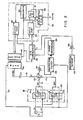
- the invention is a pressure measuring system 8 which generates an electrical signal to a generalized control unit 6 which is either the difference ⁇ P between the pressures of a chamber 18 and a chamber 20 or the pressure difference divided by a feedback term. Any of the aforementioned pressures can be communicated by suitable conduits to either of the chambers 18 and 20. Consequently, many desirable engine control parameters can be calculated directly for input to the control unit 6. For example, if the compressor pressure Pc and the inlet impact pressure Pi are the variables chosen and communicated to chambers 18 and 20, respectively, then the difference Pa-Pb will produce an engine pressure differential representative of the compressor efficiency.
- control variables are transmitted to the control unit 6 where they are operated on by generalized control laws to generate signals Ig indicative of the position of the guide vanes of the low pressure compressor, Wf indicative of the fuel flow to the engine, and Bf indicative of the position of the bypass flow nozzle.
- Ig indicative of the position of the guide vanes of the low pressure compressor
- Wf indicative of the fuel flow to the engine
- Bf indicative of the position of the bypass flow nozzle.
- many other engine control variables can be calculated in this manner.
- the system includes an alternating frequency generator 10 which generates alternating excitation signals Vr, -Vr at a certain frequency and amplitude.
- the excitation signals Vr, -Vr are preferably of the same amplitude and frequency, but of opposite phase. These signals could, for example, be generated by a sinusoidal generator connected to the primary of a transformer having a secondary winding with a grounded center tap.
- the excitation signals feed a first pressure sensing capsule 14 and a second pressure sensing capsule 16.
- Pressure capsule 14 comprises a pressure sensitive capacitor Csa and a relatively pressure insensitive reference capacitor Cra.
- pressure sensing capsule 16 comprises a pressure sensitive capacitor Csb and a relatively pressure insensitive reference capacitor Crb.
- each capsule is a quartz capacitive transducer as will be more fully described hereinafter.
- The'two pressure sensitive capacitors of the capsules 14 and 16 are fed out of phase such that the excitation Vr is fed to the pressure sensitive capacitor Csa and the excitation, -Vr, 180° out of phase with the former excitation, is fed to the pressure sensitive capacitor Csb.
- the relatively pressure insensitive reference capacitors of the capsules 14 and 16 are additionally fed out of phase.
- the reference capacitor Cra is fed by the excitation -Vr and the reference capacitor Crb is fed by the excitation Vr. It is noted that with these connections the excitation of the sensitive and reference capacitors of each capsule is also inverted.
- the two outputs of the capsule 14 are combined via lead 15 to output a current Ipa to a summing junction 22. Additionally, the output leads of the capsule 16 are combined via lead 17 to output a current Ipb to the summing junction 22.
- Each of the pressure capsules 14 and 16 are mounted in the separate pressure chambers 18 and 20 of the system which communicate to pressures Pa and Pb, respectively. Conventional mounting techniques are utilized for exposing the capsules to the pressures in chambers 18 and 20.
- the pressure sensitive capacitor Csa when fed by the excitation Vr develops a current proportional to its capacitance and likewise the reference capacitor Cra fed by the excitation -Vr develops a current proportional to its capacitance. These currents are differenced in the lead 15 because of their opposite polarities to become the current lpa. It is readily evident that if Csa and Cra are equivalent at an initial reference pressure then the output current Ipa from the lead 15 will be zero. However, when Csa changes with variances in pressure the current Ipa will be generated proportional to the change in capacitance value of Csa due to the variances in pressure Pa. Csa may change either above or below the value of Cra and, thus, the polarity and magnitude of the current Ipa is proportional to the pressure to be measured in chamber 18.
- the pressure sensitive capacitor Csb develops a current proportional to its capacitance and likewise the reference capacitor Crb develops a current proportional to its capacitance. These currents are differenced in the lead 17 because of their opposite polarities to provide a current Ipb. As with the previous capsule, Ipb is proportional to the change in the capacitor Csb and, thus, proportional to the pressure Pb to be measured in chamber 20.
- the currents lpa, Ipb are subsequently combined in the summing junction 22.
- the pressure sensitive capacitor Csa is fed 180° out of phase with the pressure sensitive capacitor Csb the output of the summing junction 22 will be an error current le which is the difference Ipa-Ipb. This current is then proportional to the differential pressure Pa-Pb.
- reference capacitors Cra, Crb are not necessary to the formation of an error current proportional to the pressure difference Pa-Pb. They are included in Figure 2 to illustrate an advantageous use by providing a capacitance from capsules 14, 16 which is closer to zero for an initial reference pressure. Since the values of Csa and Csb, are differenced, in many applications, the reference capacitors will be superfluous.
- the conversion of the error current le into a digital number is obtained by closing a loop around the summing junction 22 and calculating the amount of feedback current If that will be necessary to null or balance the error current.
- the resolution in the system in the digital domain is made by incrementally varying the feedback current If and counting the number of increments necessary for balance to determine the differential pressure.
- the error current le is transmitted to a current-to-voltage amplifier 24 where it is multiplied by a gain K1.
- the amplitude of the alternating voltage, representing the magnitude of the error is thereafter fed to a demodulator and filter 26 which additionally has an input reference signal Vr from the generator 10.
- the error voltage output from amplifier 24 is demodulated and filtered into a DC voltage with an amplitude proportional to the error signal.
- the DC voltage is transmitted through a phase compensation network 28 and is thereafter input to one port of a multiplexing analog to digital (A/D) converter 30.
- A/D analog to digital
- Another input for a second port of the A/D converter 30 is a temperature signal from a temperature sensor 50.
- the temperature signal is transmitted to the A/D converter 30 after amplification by amplifier 48 having a gain of K3.
- the temperature sensor generates a temperature signal indicative of the ambient temperature of the environment in which the system is operating.
- the temperature sensor is preferably located in physical proximity to the pressure chambers 18 and 20.
- the A/D converter 30 transforms the analog signals input to both of its ports into digital numbers to be input to a digital processor, preferably a microprocessor, illustrated as block 46.
- the processor 46 could be included as part of the control unit 6 or a separate element.
- the digital numbers are input to the processor 46 through an input port 32.
- the two digital signals representative of error and temperature are necessary to determine the differential pressure by a calibration mapping routine as will be more fully described hereinafter.
- the digital form of the error signal contains information as to the sign and magnitude of the error.
- the sign of the error indicates the direction in which the feedback current must be changed to balance the system while the magnitude of the error informs the system of the amount the feedback current must change to be in balance.
- This digital error signal can be any bit length required for the designed resolution of the system.
- the digital form of the temperature signal is generally of any required bit size and contains information as to the magnitude of the ambient temperature.
- the input port 32 is further connected to a digital integrator 34 with a proportional gain of K2.
- the integrator 34 can be implemented as an internal processor register with the gain being the size and frequency of its incrementation. Additionally, the input port 32 can transmit the digital input to a calibration mapping routine 36.
- the output of the digital integrator 34 which is a digital number N, is fed back to the summing junction 22 through an output port 38 under supervision of the sequencer 44 to a register 40.
- the sequencer 44 internal to the microprocessor as either hardware or software, communicates with the input port 32, output port 38, A/D converter 30, calibration mapping routine 36 and register 40 to synchronize the process of inputting and outputting the digital numbers.
- the digital number N stored in the register 40 is thereafter converted to an analog alternating signal by a multiplying digital-to-analog converter (MDAC) 42.
- MDAC digital-to-analog converter
- the MDAC 42 receives as another input -Vr from the reference generator 10 via lead 52.
- the MDAC 42 will output an alternating signal -V F f(N) which has a frequency and phase equivalent to -Vr and an amplitude which is a function of N. Consequently, a feedback excitation signal is generated in phase with the reference -Vr and of an amplitude proportional t Q the digital number N.
- the feedback excitation signal is applied to a relatively stable feedback capacitor Cf.
- the capacitor Cf transforms the signal into a feedback current If which is subtracted from the summing junction 22.
- the feedback current is increased or decreased incrementally by the counting of the digital integrator.34 until the loop is balanced and the error current is nulled.
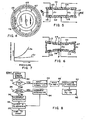
- FIG. 8 The flow chart illustrated in Figure 8 will now be used to further describe the conversion of the error signal into a digital number N.
- This flow chart represents the functional steps,in a program stored in processor 46 for converting the measured differential pressures into a digital number.
- the program can be a part of a major fuel control program where it is called as a subroutine or a separate stand alone block where the result is output directly to control unit 6.
- the sequence of process steps begins by inputting the error signal as defined by block 80. This is accomplished by signalling the A/D converter 30 that the DC error signal from phase compensation circuit 28 should be converted to a digital number. After the conversion, the output of the A/D converter is transferred to a register internal to the processor for storage by means of the input port 32.
- the error signal which has a magnitude and sign is thereafter tested during process steps 82 and 84.
- the error signal is first tested in block 82 to determine if its magnitude is greater than zero. If non zero, then the digital number N is not indicative of the error signal and the loop has not settled. Therefore, an indication of which direction to increment the number N must be found.
- the test accomplished in block 84 provides this indication. If the error signal is positive, then the error current le is larger than the feedback current If and integrator 34 is incremented by step 94 to increase the feedback current. If the error signal is negative, then the error current le is less than the feedback current If and integrator 34 is decremented by step 96 to decrease the feedback current.
- the new digital number N will be output to register 40 through the output port 38 during step 98.
- the number N is fed back to vary the error current in a direction to null the loop through the MDAC 42 and feedback capacitor Cf. This process is continued by jumping to block 80 from block 100 after the number N is output.
- the integration rate for integrator 34 will be a function of the program execution time and the size of the increment input to the integral stored each pass.
- the sequencer 44 can be made to' change either of these parameters and thus make the integration rate variable.
- a variable integration rate would be advantageous, for example, when it was desired that the settlement time of loop be improved. In such a case, as taught by the above mentioned application, the integration rate would be increased for larger error currents and reduced for N numbers near the balance point.
- the program will continue to vary the feedback current by increments in this manner until the error current is nulled.
- the sequence will flow from the test in block 82 to block 86.
- the sequencer 44 will signal A/D converter 30 to convert the output of the temperature sensor 50 into a digital number.
- the temperature signal T will then be input through the input port 32 and stored. This step in the sequence is illustrated as block 86.
- the system will now begin a calibration cycte where the stored values of N and T are read during step 88 and the corresponding ⁇ P value found from a calculation accomplished by block 90.
- the calculation step can be accomplished by one of two alternative methods.
- a look-up table of the values of the number N, differential pressure ⁇ P, and temperature T is composed empirically.
- An initial calibration is formed by exposing the system to a matrix of known differential pressures and temperatures and recording the digital number N produced for each point.
- Each point is placed in a memory element, such as a read only memory (ROM), to form a look-up table.
- the look-up table may then be used to find the differential pressure Pa-Pb which corresponds to the measured values for N and T during gas turbine engine operation. If necessary an interpolation routine can be used to find the differential pressure between two empirical points.
- An alternate method is to derive, from the calibration data for known pressures and temperatures, an equation for the differential pressure ⁇ P as a function of the variables N and T. Then to obtain an indication of an unknown differential pressure, this equation can be executed in the software loop to convert the measured parameters N and T to a representation of the unknown differential pressure.
- the differential pressure Pa-Pb is thereafter output during step 92 to be directly used by control unit 6 or for use in a larger program or processor.
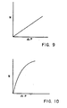
- a representative calibration characteristic of N versus ⁇ P is illustrated in Figure 9.
- N (Xf/Xm)Nmax, where Xf is the reactance of the feedback loop, Xm is the reactance of the pressure measuring input, and Nmax is the maximum digital output from the system.
- N is proportional to:
- the feedback capsule 12 has a pressure sensitive capacitor Csf and a relatively pressure insensitive reference. capacitor Crf.
- the capacitors are fed out of phase by splitting the feedback signal -Vrf(N) generated from the MDAC 42.
- the capacitor Csf is excited directly by the feedback signal and a 180° phase shift is provided by inverting amplifier 43 for the reference capacitor Crf.
- the outputs of the capsule 12 are differenced in lead 19 to become the feedback current If for the second embodiment.
- the capsule 12 is placed in one of the pressure chambers 18 and 20 to provide a pressure variable term in the denominator of the system transfer function.
- the capsule 12 is placed in the pressure chamber 18. Therefore, the transfer function as previously indicated is: where Xf is the reactance of the feedback loop and is now equal to and where Xm is the reactance of the measuring part and is equal to which reduces to Since Csa and Csf vary with Pa; Csb varies with Pb; and Cra, Crb, and Crf are relatively fixed, then N is proportional to:
- the embodiment shown in Figure 3 measures the differential pressure in the same manner as the system illustrated in Figure 2. Specifically, the feedback current If is incremented, in one direction or the other, until the error current le is forced to a null value. At that time the temperature signal T and the digital number N are communicated to a calibration routine. A look-up table where values of Pa-Pb have been stored is interrogated with respect to the measured number N and temperature T to yield the final differential.
- FIGs 4, 5, and 6 illustrate the preferred implementation of the quartz capacitive capsules which are schematically shown in Figures 2 and 3 as elements 12, 14, and 16.
- Each transducer comprises two relatively flat opposing discs 111, 112, of quartz or a similar vitreous material with similar temperature and flexion characteristics. Quartz is preferable because of its deflection characteristics with respect to pressure is relatively large, while changes in that characteristic with respect to temperature is relatively insignificant.
- each disc for example, disc 112
- the plates are comprised of a noble material such as copper, gold, silver, or a similar material.
- Plate 116 is circular in shape and substantially centrally located on the disc while plate 115 is ring-shaped and peripherally positioned on the disc 112 surrounding the inner plate 116.
- the discs are joined by an annular frit 117 along their peripheral edge to form a gap between them.
- the frit 117 is of an insulating material and the interior of the transducer is evacuated or set at a reference pressure Pr.
Landscapes
- Physics & Mathematics (AREA)
- General Physics & Mathematics (AREA)
- Measuring Fluid Pressure (AREA)
- Transmission And Conversion Of Sensor Element Output (AREA)
Claims (6)


Applications Claiming Priority (2)
| Application Number | Priority Date | Filing Date | Title |
|---|---|---|---|
| US244184 | 1981-03-16 | ||
| US06/244,184 US4457179A (en) | 1981-03-16 | 1981-03-16 | Differential pressure measuring system |
Publications (2)
| Publication Number | Publication Date |
|---|---|
| EP0061940A1 EP0061940A1 (fr) | 1982-10-06 |
| EP0061940B1 true EP0061940B1 (fr) | 1986-03-26 |
Family
ID=22921700
Family Applications (1)
| Application Number | Title | Priority Date | Filing Date |
|---|---|---|---|
| EP82400192A Expired EP0061940B1 (fr) | 1981-03-16 | 1982-02-04 | Système de mesure de pression différentielle |
Country Status (5)
| Country | Link |
|---|---|
| US (1) | US4457179A (fr) |
| EP (1) | EP0061940B1 (fr) |
| JP (1) | JPS57158533A (fr) |
| CA (1) | CA1168755A (fr) |
| DE (1) | DE3270059D1 (fr) |
Families Citing this family (28)
| Publication number | Priority date | Publication date | Assignee | Title |
|---|---|---|---|---|
| US4434664A (en) * | 1981-07-06 | 1984-03-06 | The Bendix Corporation | Pressure ratio measurement system |
| US4532809A (en) * | 1981-10-05 | 1985-08-06 | Allied Corporation | Pressure measuring systems with increased accuracy for a constant resolution |
| US4422125A (en) * | 1982-05-21 | 1983-12-20 | The Bendix Corporation | Pressure transducer with an invariable reference capacitor |
| US4618856A (en) * | 1985-05-03 | 1986-10-21 | Allied Corporation | Stall surge detector |
| US4982351A (en) * | 1986-05-05 | 1991-01-01 | Texas Instruments Incorporated | Low cost high precision sensor |
| US5051937A (en) * | 1986-05-05 | 1991-09-24 | Texas Instruments Incorporated | Low cost high precision sensor |
| US4951236A (en) * | 1986-05-05 | 1990-08-21 | Texas Instruments Incorporated | Low cost high precision sensor |
| US4872349A (en) * | 1986-10-31 | 1989-10-10 | General Electric Company | Microcomputerized force transducer |
| US4987782A (en) * | 1989-10-03 | 1991-01-29 | Allied-Signal Inc. | Capacitive pressure transducer system |
| EP0543901B1 (fr) * | 1990-08-17 | 1995-10-04 | Analog Devices, Inc. | Accelerometre monolithique |
| US5163326A (en) * | 1991-03-08 | 1992-11-17 | Rosemount Inc. | Line pressure compensator for a pressure transducer |
| US5241850A (en) * | 1991-11-01 | 1993-09-07 | Texas Instruments Incorporated | Sensor with programmable temperature compensation |
| CA2142189A1 (fr) * | 1992-08-10 | 1994-02-17 | Hilger A. Walter | Adaptateur pour le montage d'un capteur de pression sur l'enveloppe d'une turbine |
| EP0654163B1 (fr) * | 1992-08-10 | 2000-07-26 | Dow Deutschland Inc. | Procede et dispositif permettant de surveiller l'excitation vibratoire d'un compresseur axial |
| AU4637393A (en) * | 1992-08-10 | 1994-03-03 | Dow Deutschland Inc. | Process for detecting fouling of an axial compressor |
| WO1994003862A1 (fr) * | 1992-08-10 | 1994-02-17 | Dow Deutschland Inc. | Procede et dispositif de controle et de regulation d'un compresseur |
| US5528520A (en) * | 1994-12-08 | 1996-06-18 | Ford Motor Company | Calibration circuit for capacitive sensors |
| US5604315A (en) * | 1995-01-12 | 1997-02-18 | Setra Systems, Inc. | Apparatus using a feedback network to measure fluid pressures |
| US5705978A (en) * | 1995-09-29 | 1998-01-06 | Rosemount Inc. | Process control transmitter |
| US5808198A (en) * | 1997-05-19 | 1998-09-15 | The Charles Stark Draper Laboratory, Inc. | RF balanced capacitive vibration sensor system |
| US6879056B2 (en) * | 2000-12-29 | 2005-04-12 | Intel Corporation | Converting sensed signals |
| US6910381B2 (en) * | 2002-05-31 | 2005-06-28 | Mykrolis Corporation | System and method of operation of an embedded system for a digital capacitance diaphragm gauge |
| KR100954157B1 (ko) * | 2007-12-21 | 2010-04-20 | 한국항공우주연구원 | 터보기계 블레이드 파손 모니터링 유닛 및 이를 갖는 터보장치 |
| CN102141455B (zh) * | 2010-12-10 | 2014-06-25 | 北京航空航天大学 | 一种非介入式压力测量方法 |
| WO2014042727A2 (fr) | 2012-06-12 | 2014-03-20 | Trxs Systems, Inc. | Procédés de détermination de l'altitude d'un collaborateur ou d'un bien surveillé |
| US9322648B1 (en) | 2012-06-12 | 2016-04-26 | Trx Systems, Inc. | Reducing elevation error with environmental pressure anomaly compensation |
| CN113483946B (zh) * | 2021-06-01 | 2023-04-28 | 广西防城港核电有限公司 | 差压变送器充水排气系统及方法 |
| CN114279626B (zh) * | 2021-12-06 | 2024-07-16 | 北京晨晶电子有限公司 | 一种基于薄膜电容器的气体真空度检测方法及系统 |
Family Cites Families (8)
| Publication number | Priority date | Publication date | Assignee | Title |
|---|---|---|---|---|
| US3237178A (en) * | 1963-11-01 | 1966-02-22 | Honeywell Inc | Control apparatus |
| US3657630A (en) * | 1968-10-09 | 1972-04-18 | Trw Inc | Electro servosystem for a force balancing gauge |
| US3595084A (en) * | 1970-02-27 | 1971-07-27 | Continental Can Co | Digital transducer system |
| US3858097A (en) * | 1973-12-26 | 1974-12-31 | Bendix Corp | Pressure-sensing capacitor |
| US4001813A (en) * | 1975-07-02 | 1977-01-04 | The Bendix Corporation | Precision capacitance to digital conversion system |
| US4153873A (en) * | 1977-10-11 | 1979-05-08 | Rosemount Inc. | Transducer for converting a varying analog current signal to a binary digital signal |
| JPS55159109A (en) * | 1979-05-30 | 1980-12-11 | Yokogawa Hokushin Electric Corp | Capacity type displacement converter |
| US4322977A (en) * | 1980-05-27 | 1982-04-06 | The Bendix Corporation | Pressure measuring system |
-
1981
- 1981-03-16 US US06/244,184 patent/US4457179A/en not_active Expired - Fee Related
- 1981-12-07 CA CA000391658A patent/CA1168755A/fr not_active Expired
-
1982
- 1982-02-04 EP EP82400192A patent/EP0061940B1/fr not_active Expired
- 1982-02-04 DE DE8282400192T patent/DE3270059D1/de not_active Expired
- 1982-03-02 JP JP57031854A patent/JPS57158533A/ja active Pending
Also Published As
| Publication number | Publication date |
|---|---|
| JPS57158533A (en) | 1982-09-30 |
| US4457179A (en) | 1984-07-03 |
| CA1168755A (fr) | 1984-06-05 |
| DE3270059D1 (en) | 1986-04-30 |
| EP0061940A1 (fr) | 1982-10-06 |
Similar Documents
| Publication | Publication Date | Title |
|---|---|---|
| EP0061940B1 (fr) | Système de mesure de pression différentielle | |
| EP0040996B1 (fr) | Système digital pour la mesure de pression | |
| EP0069647B1 (fr) | Système de mesure d'un rapport de pression | |
| EP0061359B1 (fr) | Transducteur capacitif de pression | |
| US4449409A (en) | Pressure measurement system with a constant settlement time | |
| KR100883618B1 (ko) | 오차 보상을 개선한 공정 압력 측정 장치 | |
| SU593674A3 (ru) | Датчик давлени | |
| US4570490A (en) | Differential pressure ratio measurement system | |
| US3965746A (en) | Pressure transducer | |
| US5471884A (en) | Gain-adjusting circuitry for combining two sensors to form a media isolated differential pressure sensor | |
| EP0290574A1 (fr) | Transducteur de pression a thermocompensation numerique integree | |
| JPS6021330B2 (ja) | 多重機能圧力センサ | |
| EP0198855A1 (fr) | Circuit pour detecteur capacitif en materiaux friables | |
| EP0309644A3 (fr) | Appareils correcteurs de volume électroniques | |
| US4532809A (en) | Pressure measuring systems with increased accuracy for a constant resolution | |
| Mandle et al. | A new micromachined silicon high-accuracy pressure sensor | |
| JP3329480B2 (ja) | 差圧測定装置 | |
| CN210464785U (zh) | 一种双极电容式真空计及其对应的测量电路 | |
| JPS6147371B2 (fr) | ||
| SU1631328A1 (ru) | Устройство дл измерени давлени | |
| US2925732A (en) | Machmeter | |
| Votava | Pressure Sensors: Techniques and Materials | |
| SU821973A1 (ru) | Датчик давлени | |
| HEERENS | Theory and applications of an absolutely calibrated membrane differential pressure gauge(Dutch thesis) | |
| CHELNER et al. | RANGE COMMANDERS COUNCIL |
Legal Events
| Date | Code | Title | Description |
|---|---|---|---|
| PUAI | Public reference made under article 153(3) epc to a published international application that has entered the european phase |
Free format text: ORIGINAL CODE: 0009012 |
|
| 17P | Request for examination filed |
Effective date: 19820210 |
|
| AK | Designated contracting states |
Designated state(s): DE FR GB SE |
|
| RAP1 | Party data changed (applicant data changed or rights of an application transferred) |
Owner name: ALLIED CORPORATION |
|
| GRAA | (expected) grant |
Free format text: ORIGINAL CODE: 0009210 |
|
| AK | Designated contracting states |
Kind code of ref document: B1 Designated state(s): DE FR GB SE |
|
| REF | Corresponds to: |
Ref document number: 3270059 Country of ref document: DE Date of ref document: 19860430 |
|
| ET | Fr: translation filed | ||
| PLBE | No opposition filed within time limit |
Free format text: ORIGINAL CODE: 0009261 |
|
| STAA | Information on the status of an ep patent application or granted ep patent |
Free format text: STATUS: NO OPPOSITION FILED WITHIN TIME LIMIT |
|
| 26N | No opposition filed | ||
| PGFP | Annual fee paid to national office [announced via postgrant information from national office to epo] |
Ref country code: GB Payment date: 19890131 Year of fee payment: 8 |
|
| PGFP | Annual fee paid to national office [announced via postgrant information from national office to epo] |
Ref country code: SE Payment date: 19890208 Year of fee payment: 8 |
|
| PGFP | Annual fee paid to national office [announced via postgrant information from national office to epo] |
Ref country code: FR Payment date: 19890209 Year of fee payment: 8 |
|
| PGFP | Annual fee paid to national office [announced via postgrant information from national office to epo] |
Ref country code: DE Payment date: 19890323 Year of fee payment: 8 |
|
| PG25 | Lapsed in a contracting state [announced via postgrant information from national office to epo] |
Ref country code: GB Effective date: 19900204 |
|
| PG25 | Lapsed in a contracting state [announced via postgrant information from national office to epo] |
Ref country code: SE Effective date: 19900205 |
|
| GBPC | Gb: european patent ceased through non-payment of renewal fee | ||
| PG25 | Lapsed in a contracting state [announced via postgrant information from national office to epo] |
Ref country code: FR Effective date: 19901031 |
|
| PG25 | Lapsed in a contracting state [announced via postgrant information from national office to epo] |
Ref country code: DE Effective date: 19901101 |
|
| REG | Reference to a national code |
Ref country code: FR Ref legal event code: ST |
|
| EUG | Se: european patent has lapsed |
Ref document number: 82400192.9 Effective date: 19901107 |