EP0061969A2 - Tunnelvortriebsmaschine mit einem mit Werkzeugen ausgerüsteten Drehbohrkopf und einer Vorrichtung zum Montieren der Ausbauelemente - Google Patents
Tunnelvortriebsmaschine mit einem mit Werkzeugen ausgerüsteten Drehbohrkopf und einer Vorrichtung zum Montieren der Ausbauelemente Download PDFInfo
- Publication number
- EP0061969A2 EP0061969A2 EP82400533A EP82400533A EP0061969A2 EP 0061969 A2 EP0061969 A2 EP 0061969A2 EP 82400533 A EP82400533 A EP 82400533A EP 82400533 A EP82400533 A EP 82400533A EP 0061969 A2 EP0061969 A2 EP 0061969A2
- Authority
- EP
- European Patent Office
- Prior art keywords
- head
- panel
- tunnel
- elevator
- section
- Prior art date
- Legal status (The legal status is an assumption and is not a legal conclusion. Google has not performed a legal analysis and makes no representation as to the accuracy of the status listed.)
- Granted
Links
Images


Classifications
-
- E—FIXED CONSTRUCTIONS
- E21—EARTH OR ROCK DRILLING; MINING
- E21D—SHAFTS; TUNNELS; GALLERIES; LARGE UNDERGROUND CHAMBERS
- E21D11/00—Lining tunnels, galleries or other underground cavities, e.g. large underground chambers; Linings therefor; Making such linings in situ, e.g. by assembling
- E21D11/40—Devices or apparatus specially adapted for handling or placing units of linings or supporting units for tunnels or galleries
Definitions
- the invention relates to a TBM with a rotating tool holder head fitted with a device for installing tunnel support panels.
- the invention is essentially distinguished by the fact that the device for installing the retaining panels is integrated into the rotating tool holder head of the boring machine.
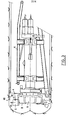
- the tunnel boring machine shown in the figures comprises a head rotatably mounted on a chassis movable in translation in the tunnel.
- the axis of rotation is substantially the axis of the tunnel.
- On the head are articulated arms which carry the drilling tools of the tunnel.
- the arms are articulated so as to be able to oscillate on the head around axes distributed in a plane which is perpendicular to the axis of the gallery.
- Means (not shown) are provided for controlling an advancement of the head, the rotation of the head on itself and the oscillation of the arms, according to the working phase of the tunnel boring machine.
- the support must be carried out by means of five curved panels 1 to 5, for example of concrete, cast iron or steel. These panels have for example a thickness of the order of 20 to 30 cm and a length (measured parallel to the axis of the gallery) of the order of 70 to 80 cm. Four panels are identical but the fifth (panel 2 in Figure 1) is narrower.
- the installation technique consists of installing the large lower panel 1, then the small lower panel 2, then one of the side panels 3 and 4, the other of the side panels and finally the upper panel 5.
- This panel was placed on a conveyor 6 (FIG. 2), for example a conveyor belt which moved this panel to a radial elevator schematized in the figures by a jack.
- the elevator can practically be reduced to a radial jack whose rod 7 is provided with any suitable means for fixing the panel to the end of the rod, for example a ball joint or other articulation, a magnetic means, a clamping medium, etc.
- the internal face of the panel comprises, as necessary, a means capable of cooperating with the rod fixing means for the temporary fixing of the panel to the rod 7.
- the cylinder 8 of the jack is fixed to the rotating head 9 of the TBM between the arms 10 which carry the tools 17 in substantially the same cross section as the joints of the tool arms.
- the head also carries deflectors 11 which, when the TBM is in service, acting to move the materials detached by the tools towards a conveyor 12 (FIG. 2) which evacuates them towards the rear of the TBM, in a manner known per se.
- the head of the TBM is rotated to bring the elevator to the vertical position.
- the TBM includes specific means for controlling a limited rotation of the head to make accessible, for example, a tool holder for a tool change
- these means are used which control the limited rotation to also control the rotation of the 'elevator.
- the conveyor is then moved back behind the head.
- Figure 3 shows the conveyor in the retracted position.
- the actuator 7,8 When the conveyor has been moved back, the actuator 7,8 is actuated to raise the panel 3, as shown diagrammatically by the arrow 13 in FIG. 2, until it is applied against the top of the gallery section to be supported.
- the head 9 is then rotated, the rod of the jack remaining out, in order to slide the panel against the wall of the tunnel into its operating position shown in FIG. 1.
- the rod and the panel are then separated, the rod is retracted and the head is rotated to return the actuator to its initial upper position.
- the conveyor 6 is then moved forward to feed the cylinder with the following panel 4 and the laying cycle begins again.
- the last panel will be the key to the hanger.
- this panel must necessarily have a particular cut necessary for its introduction between the panels already in place, by a movement from the bottom up.
- advantage is taken of the movement possibilities of the tunnel boring machine in order to be able to use a panel without any particular cutout.
- the invention is suitable for the installation of support panels and also for the installation of hangers, in general.
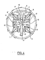
- FIG. 4 represents an alternative embodiment in which the elevator comprises a radial cylinder (double), the cylinders 8,8 'of which are fixed to one of the tool-carrying arms 10.
- the invention is not limited to these exemplary embodiments. It is not going beyond the scope of the invention to modify the number of tools for the tunneling machine, the number of arms of the tunneling machine, or the structure of the device for installing the panels.
- This device may include a mechanism between a jack or other motor means and the panel to be installed.
Landscapes
- Engineering & Computer Science (AREA)
- Mining & Mineral Resources (AREA)
- General Life Sciences & Earth Sciences (AREA)
- Structural Engineering (AREA)
- Civil Engineering (AREA)
- Life Sciences & Earth Sciences (AREA)
- Architecture (AREA)
- Geochemistry & Mineralogy (AREA)
- Geology (AREA)
- Lining And Supports For Tunnels (AREA)
- Earth Drilling (AREA)
- Excavating Of Shafts Or Tunnels (AREA)
- Coating Apparatus (AREA)
Priority Applications (1)
| Application Number | Priority Date | Filing Date | Title |
|---|---|---|---|
| AT82400533T ATE18688T1 (de) | 1981-03-26 | 1982-03-24 | Tunnelvortriebsmaschine mit einem mit werkzeugen ausgeruesteten drehbohrkopf und einer vorrichtung zum montieren der ausbauelemente. |
Applications Claiming Priority (2)
| Application Number | Priority Date | Filing Date | Title |
|---|---|---|---|
| FR8106087A FR2502687A1 (fr) | 1981-03-26 | 1981-03-26 | Dispositif pour la pose, a l'avancement, de panneaux de soutenement dans une galerie, procede pour la mise en oeuvre du dispositif et application |
| FR8106087 | 1981-03-26 |
Publications (3)
| Publication Number | Publication Date |
|---|---|
| EP0061969A2 true EP0061969A2 (de) | 1982-10-06 |
| EP0061969A3 EP0061969A3 (en) | 1984-07-25 |
| EP0061969B1 EP0061969B1 (de) | 1986-03-19 |
Family
ID=9256675
Family Applications (1)
| Application Number | Title | Priority Date | Filing Date |
|---|---|---|---|
| EP82400533A Expired EP0061969B1 (de) | 1981-03-26 | 1982-03-24 | Tunnelvortriebsmaschine mit einem mit Werkzeugen ausgerüsteten Drehbohrkopf und einer Vorrichtung zum Montieren der Ausbauelemente |
Country Status (10)
| Country | Link |
|---|---|
| EP (1) | EP0061969B1 (de) |
| JP (1) | JPS58106100A (de) |
| AT (1) | ATE18688T1 (de) |
| AU (1) | AU557374B2 (de) |
| CA (1) | CA1179383A (de) |
| DE (1) | DE3269925D1 (de) |
| ES (1) | ES510799A0 (de) |
| FR (1) | FR2502687A1 (de) |
| SU (1) | SU1246899A3 (de) |
| ZA (1) | ZA821852B (de) |
Cited By (1)
| Publication number | Priority date | Publication date | Assignee | Title |
|---|---|---|---|---|
| WO2001075269A3 (en) * | 2000-03-31 | 2001-12-13 | Link Pipe Inc | Tunnel lining apparatus and method |
Families Citing this family (3)
| Publication number | Priority date | Publication date | Assignee | Title |
|---|---|---|---|---|
| AT11365U1 (de) * | 2006-01-26 | 2010-09-15 | Florianer Bahn Forschungs & Errichtungsgesellschaft Mbh | Verfahren und vorrichtung zur lagestabilisierung von tunnelausbauelementen |
| CN102322278B (zh) * | 2011-07-23 | 2013-08-28 | 上海城建市政工程(集团)有限公司 | 隧道中隔墙施工专用机械 |
| CN116378686B (zh) * | 2023-05-06 | 2026-02-17 | 河南五建建设集团有限公司 | 盾构机用盾体撑紧装置和盾构机 |
Family Cites Families (5)
| Publication number | Priority date | Publication date | Assignee | Title |
|---|---|---|---|---|
| US2385251A (en) * | 1943-02-22 | 1945-09-18 | Ayers Frederick Percival | Tunneling method |
| FR1197818A (fr) * | 1957-01-12 | 1959-12-03 | Oesterreichisches Schacht U Ti | Machine destinée au percement de galeries |
| FR1401555A (fr) * | 1964-05-29 | 1965-06-04 | Robbins & Assoc James S | érecteurs de segments et tube de convoyeur monté universellement pour une machine à creuser les tunnels |
| JPS5438814A (en) * | 1977-09-02 | 1979-03-24 | Ricoh Kk | Platen for printing |
| DE2909918C3 (de) * | 1979-03-14 | 1985-06-05 | Bochumer Eisenhütte Heintzmann GmbH & Co, 4630 Bochum | Vorrichtung zum Vortreiben und Ausbauen einer untertägigen Strecke |
-
1981
- 1981-03-26 FR FR8106087A patent/FR2502687A1/fr active Granted
-
1982
- 1982-03-19 ZA ZA821852A patent/ZA821852B/xx unknown
- 1982-03-19 CA CA000398863A patent/CA1179383A/en not_active Expired
- 1982-03-24 EP EP82400533A patent/EP0061969B1/de not_active Expired
- 1982-03-24 AT AT82400533T patent/ATE18688T1/de active
- 1982-03-24 DE DE8282400533T patent/DE3269925D1/de not_active Expired
- 1982-03-25 ES ES510799A patent/ES510799A0/es active Granted
- 1982-03-25 AU AU81912/82A patent/AU557374B2/en not_active Ceased
- 1982-03-25 JP JP57048103A patent/JPS58106100A/ja active Pending
- 1982-03-25 SU SU823413400A patent/SU1246899A3/ru active
Cited By (1)
| Publication number | Priority date | Publication date | Assignee | Title |
|---|---|---|---|---|
| WO2001075269A3 (en) * | 2000-03-31 | 2001-12-13 | Link Pipe Inc | Tunnel lining apparatus and method |
Also Published As
| Publication number | Publication date |
|---|---|
| AU557374B2 (en) | 1986-12-18 |
| CA1179383A (en) | 1984-12-11 |
| DE3269925D1 (en) | 1986-04-24 |
| ATE18688T1 (de) | 1986-04-15 |
| FR2502687A1 (fr) | 1982-10-01 |
| ZA821852B (en) | 1983-01-26 |
| JPS58106100A (ja) | 1983-06-24 |
| FR2502687B1 (de) | 1984-06-08 |
| ES8306214A1 (es) | 1983-06-01 |
| EP0061969A3 (en) | 1984-07-25 |
| EP0061969B1 (de) | 1986-03-19 |
| AU8191282A (en) | 1982-09-30 |
| SU1246899A3 (ru) | 1986-07-23 |
| ES510799A0 (es) | 1983-06-01 |
Similar Documents
| Publication | Publication Date | Title |
|---|---|---|
| FR2489725A1 (fr) | Machine pour percer des pieces meplates en forme de plaque, telles que des vitres | |
| EP0105228B1 (de) | Einrichtung zum Abtrennen eines Rohrstückes aus steifem Material, insbesondere mit ovalem Querschnitt, wie beispielsweise eines Gussrohres | |
| EP0588713B1 (de) | Fräs-, Planfräs- und Polier-Maschine für automatischen Werkzeugwechsel und entsprechende Vorrichtung | |
| EP0061969B1 (de) | Tunnelvortriebsmaschine mit einem mit Werkzeugen ausgerüsteten Drehbohrkopf und einer Vorrichtung zum Montieren der Ausbauelemente | |
| EP0128432B1 (de) | Stichlochbohrmaschine für Schachtöfen | |
| FR2596084A1 (fr) | Dispositif de pose de tubes par poussee, en particulier pour tubes de faible diametre | |
| FR2584006A1 (fr) | Systeme changeur de meules pour rectifieuses | |
| FR2612438A1 (fr) | Machine-outil, notamment perceuse ou taraudeuse | |
| FR2471836A1 (fr) | Dispositif pour serrer et liberer la tige conique d'un outil ou d'un accessoire sur une machine-outil, notamment sur une aleseuse ou une fraiseuse | |
| FR2585763A1 (fr) | Machine de blindage de tunnel | |
| EP0064644B1 (de) | Führungs- und Positioniermechanismus für die Bohrstange des Abstichloches am Schachtofen und Stichlochbohrmaschine mit einem solchen Mechanismus | |
| FR2602542A1 (fr) | Machine miniere de creusement ou d'exploitation a coupe partielle | |
| EP0889844B1 (de) | Hebevorrichtung von einem elektrospindel einer hochgeschwindigkeitsbearbeitungswerkzeugmaschine | |
| FR2619036A1 (fr) | Machine de percage d'un trou de coulee de four a cuve | |
| WO1995019868A1 (fr) | Procede et dispositif d'assemblage d'une carrosserie automobile | |
| WO2021005174A1 (fr) | Outil d'alignement et de montage de collier sur conduite de marinage de tunnelier | |
| WO2000005029A1 (fr) | Machine-outil a structure fermee et disposition ergonomique des parties d'une telle machine-outil | |
| JP3075554B2 (ja) | エレクタ装置 | |
| FR3050758B1 (fr) | Tunnelier | |
| EP3110585B1 (de) | Drehautomaten, steuereinheit für drehautomaten und nachrüstungsverfahren für eine derartige einheit | |
| FR2461806A1 (fr) | Machine de creusement comportant un bras muni d'un outil d'abattage et orientable | |
| FR2581330A1 (fr) | Machine de tronconnage et de biseautage de tubes | |
| FR2702694A1 (fr) | Dispositif pour le chargement et le déchargement de machines à roder et pierrer. | |
| FR2645584A1 (fr) | Dispositif de creusement de galeries transversales lors du percement de tunnels ou de galeries | |
| EP0494572A1 (de) | Vorrichtung zum Zusammenbauen von Teilen auf einer Stulpschiene eines Treibstangenverschlusses für einen Drehkippflügel eines Fensters |
Legal Events
| Date | Code | Title | Description |
|---|---|---|---|
| PUAI | Public reference made under article 153(3) epc to a published international application that has entered the european phase |
Free format text: ORIGINAL CODE: 0009012 |
|
| AK | Designated contracting states |
Designated state(s): AT BE CH DE FR GB IT LU NL SE |
|
| PUAL | Search report despatched |
Free format text: ORIGINAL CODE: 0009013 |
|
| AK | Designated contracting states |
Designated state(s): AT BE CH DE FR GB IT LI LU NL SE |
|
| 17P | Request for examination filed |
Effective date: 19840910 |
|
| GRAA | (expected) grant |
Free format text: ORIGINAL CODE: 0009210 |
|
| AK | Designated contracting states |
Kind code of ref document: B1 Designated state(s): AT BE CH DE FR GB IT LI LU NL SE |
|
| REF | Corresponds to: |
Ref document number: 18688 Country of ref document: AT Date of ref document: 19860415 Kind code of ref document: T |
|
| ITF | It: translation for a ep patent filed | ||
| PG25 | Lapsed in a contracting state [announced via postgrant information from national office to epo] |
Ref country code: LU Free format text: LAPSE BECAUSE OF NON-PAYMENT OF DUE FEES Effective date: 19860331 |
|
| REF | Corresponds to: |
Ref document number: 3269925 Country of ref document: DE Date of ref document: 19860424 |
|
| PLBE | No opposition filed within time limit |
Free format text: ORIGINAL CODE: 0009261 |
|
| PGFP | Annual fee paid to national office [announced via postgrant information from national office to epo] |
Ref country code: AT Payment date: 19870223 Year of fee payment: 6 |
|
| 26N | No opposition filed | ||
| PGFP | Annual fee paid to national office [announced via postgrant information from national office to epo] |
Ref country code: NL Payment date: 19870331 Year of fee payment: 6 |
|
| PG25 | Lapsed in a contracting state [announced via postgrant information from national office to epo] |
Ref country code: AT Effective date: 19880324 |
|
| PG25 | Lapsed in a contracting state [announced via postgrant information from national office to epo] |
Ref country code: SE Effective date: 19880325 |
|
| PG25 | Lapsed in a contracting state [announced via postgrant information from national office to epo] |
Ref country code: LI Effective date: 19880331 Ref country code: CH Effective date: 19880331 |
|
| BERE | Be: lapsed |
Owner name: BOUYGUES Effective date: 19880331 |
|
| PG25 | Lapsed in a contracting state [announced via postgrant information from national office to epo] |
Ref country code: NL Effective date: 19881001 |
|
| NLV4 | Nl: lapsed or anulled due to non-payment of the annual fee | ||
| PG25 | Lapsed in a contracting state [announced via postgrant information from national office to epo] |
Ref country code: GB Free format text: LAPSE BECAUSE OF NON-PAYMENT OF DUE FEES Effective date: 19881121 |
|
| GBPC | Gb: european patent ceased through non-payment of renewal fee | ||
| PG25 | Lapsed in a contracting state [announced via postgrant information from national office to epo] |
Ref country code: FR Free format text: LAPSE BECAUSE OF NON-PAYMENT OF DUE FEES Effective date: 19881130 |
|
| REG | Reference to a national code |
Ref country code: CH Ref legal event code: PL |
|
| PG25 | Lapsed in a contracting state [announced via postgrant information from national office to epo] |
Ref country code: DE Effective date: 19881201 |
|
| REG | Reference to a national code |
Ref country code: FR Ref legal event code: ST |
|
| PG25 | Lapsed in a contracting state [announced via postgrant information from national office to epo] |
Ref country code: BE Effective date: 19890331 |
|
| EUG | Se: european patent has lapsed |
Ref document number: 82400533.4 Effective date: 19881206 |