EP0061973B1 - Metering valve operating in inverted position, for an aerosol container - Google Patents
Metering valve operating in inverted position, for an aerosol container Download PDFInfo
- Publication number
- EP0061973B1 EP0061973B1 EP82400566A EP82400566A EP0061973B1 EP 0061973 B1 EP0061973 B1 EP 0061973B1 EP 82400566 A EP82400566 A EP 82400566A EP 82400566 A EP82400566 A EP 82400566A EP 0061973 B1 EP0061973 B1 EP 0061973B1
- Authority
- EP
- European Patent Office
- Prior art keywords
- rod
- valve
- opening
- sealing ring
- container
- Prior art date
- Legal status (The legal status is an assumption and is not a legal conclusion. Google has not performed a legal analysis and makes no representation as to the accuracy of the status listed.)
- Expired
Links
- 239000000443 aerosol Substances 0.000 title 1
- 239000003380 propellant Substances 0.000 claims description 6
- 238000006073 displacement reaction Methods 0.000 claims description 2
- 238000007789 sealing Methods 0.000 claims 8
- 239000000047 product Substances 0.000 description 13
- 238000005259 measurement Methods 0.000 description 4
- 239000007789 gas Substances 0.000 description 3
- 125000006850 spacer group Chemical group 0.000 description 3
- IJGRMHOSHXDMSA-UHFFFAOYSA-N Atomic nitrogen Chemical compound N#N IJGRMHOSHXDMSA-UHFFFAOYSA-N 0.000 description 2
- 239000002775 capsule Substances 0.000 description 2
- 239000003292 glue Substances 0.000 description 1
- 239000012263 liquid product Substances 0.000 description 1
- 238000004519 manufacturing process Methods 0.000 description 1
- 229910052757 nitrogen Inorganic materials 0.000 description 1
- 238000010112 shell-mould casting Methods 0.000 description 1
- 238000003466 welding Methods 0.000 description 1
Images
Classifications
-
- B—PERFORMING OPERATIONS; TRANSPORTING
- B65—CONVEYING; PACKING; STORING; HANDLING THIN OR FILAMENTARY MATERIAL
- B65D—CONTAINERS FOR STORAGE OR TRANSPORT OF ARTICLES OR MATERIALS, e.g. BAGS, BARRELS, BOTTLES, BOXES, CANS, CARTONS, CRATES, DRUMS, JARS, TANKS, HOPPERS, FORWARDING CONTAINERS; ACCESSORIES, CLOSURES, OR FITTINGS THEREFOR; PACKAGING ELEMENTS; PACKAGES
- B65D83/00—Containers or packages with special means for dispensing contents
- B65D83/14—Containers for dispensing liquid or semi-liquid contents by internal gaseous pressure, i.e. aerosol containers comprising propellant
- B65D83/44—Valves specially adapted for the discharge of contents; Regulating devices
- B65D83/52—Metering valves; Metering devices
Definitions
- the present invention relates to a metering valve, of the type adaptable to a pressurized container, intended to contain a product to be sprayed, containing a propellant gas in solution under pressure, and allowing by pressing a button to release a determined quantity of product.
- a valve of this type is described in particular in French patent 1 287 373 in the name of Mr. Lucien Guillou for "Improvements to metering valves " .
- the valve described in this patent is intended to operate when the container is in the upright position, with the opening at the top.
- the subject of the present invention is in particular a valve of the above type, operating in the inverted position, and making it possible to dispense more precise doses, without variation of the quantity delivered on each expulsion until the bottle is exhausted, and also to allow filling the bottle in better conditions.
- Valves intended for operation with the container in the inverted position are described in documents US-A-3,394,851 (Gorman) and FR-A-2,403,833 (Glaxo).
- the device of the American patent is intended for an insoluble gas, such as nitrogen, contrary to the present invention.
- the return spring of this valve is placed towards the outside of the container, which lengthens the outlet path of the product to be sprayed, and imposes larger dimensions on the valve, which limits its applications.
- FR-A-2 403 833 the return spring of the valve is located in the bottom of the valve, and it follows that the filling of the measurement chamber can be hampered.
- the subject of the invention is a valve of the type in question, in which the return spring of the valve is placed at the bottom of the valve, but in which perfect filling of the measuring chamber is ensured during the entire use of the container. .
- the invention particularly relates to an improvement to the valve described in document FR-A-2 403 833, that is to say a valve intended to be mounted in the opening of a pressurized container, to contain a product to be sprayed containing a propellant in solution under pressure, and to expel precise doses of product when the container is kept in the inverted position with the opening down.
- the valve comprises a valve body of tubular shape, said body forming at its upper part a measurement chamber disposed near the opening of the container, delimited by a wall of generally cylindrical shape, two radial walls constituted by an annular seal greater than central opening and a lower ring seal with central opening, and an axial valve stem extending through the seals and having an upper extension extending outside the valve.
- the rod has an extra thickness between the joints making it possible to close the opening of the lower joint, the rod extending downwards by a thin part passing through the opening of the lower joint and a guide part, the upper part of the rod comprising an axial channel communicating with the outside via a passage, the passage being able by displacement of the rod, to come from one or the other of the sides of the upper seal.
- Said body further forms at its lower part a tubular housing for a return spring bearing on the one hand on the bottom of said housing and on the other hand on a shoulder formed on the rod.
- the improvement consists in that the thin part of the rod is formed by substantially radial ribs which are angularly spaced in a substantially regular manner, said ribs extending in the direction of the bottom of the housing which receives the return spring, to constitute the formed shoulder. on the stem; the aforementioned housing has angularly spaced longitudinal openings in a substantially regular manner and extending over substantially the entire height separating the bottom of the aforementioned housing and the lower seal of the measurement chamber.
- the improvement also consists in that the number of the above-mentioned longitudinal openings is less than that of the above-mentioned radial ribs.
- the valve according to the invention intended to be fixed in the opening of a container such as a bottle or the like, comprises a valve body 1 fixed in a capsule 2 with the interposition of an annular seal 3.
- the capsule 2 is itself crimped onto the neck of a container, not shown, with the interposition of another seal, in a well known manner.
- a container is intended to contain a liquid product, with a pressurized gas (called propellant) soluble in the product.
- propellant pressurized gas
- the operating principle of such a metering valve is well known. It is described in the patents cited above.
- the valve body forms at its upper part a measurement chamber 13 and at its lower part a housing 30 for a return spring.
- the words upper, lower, upper or lower relate to the right position of the container, with the opening upwards.
- valve stem 4 AT the inside of the valve body is arranged a valve stem 4 of which a part 5 extends to the outside, through the seal 3.
- This stem has an axial or longitudinal channel 6 opening at the outer end of the stem and communicating with a radial passage 7.
- the rod 4 is pushed upwards by a spring 8 and comes to bear against the seal 3 by a shoulder 9.
- the passage 7 opens above the seal (possibly in the seal, but not below) so that the bottle is closed, and the product under pressure cannot exit.
- the rod 4 is extended in the interior of the container by an enlarged part or piston 11, for example of the same diameter as the shoulder 9, and an annular seal 12 is disposed at a certain distance from the piston, the central opening 31 of the gasket 12 corresponding to the diameter of the piston 11.
- the container is turned over, placing the opening with the valve at the bottom.
- a closed volume, or chamber 13 which contains a dose, the volume of which is precisely determined, of the product to be sprayed loaded with propellant dissolved under pressure.
- the opening of the passage 7 appears in the chamber 13, and the content thereof is then evacuated by the passage 7 and the channel 6, under the effect propellant which is released as a result of the drop in pressure.
- the rod 4 is released which is returned to its initial position by the return spring 8.
- the chamber 13 is then opened. To reload the dosing chamber, keep the container upside down.
- the product reaches the chamber 13 through at least one opening provided in the bottom of the valve body, below the seal 12.
- the rod 4 advantageously extends by a thinned part 14 having for example a shoulder 15 for the support of the spring.
- the rod 4 ends with a barrel 16 engaged between the turns of the spring and used for guiding and centering the rod 4.
- the thinned part 14 has dimensions such that in the rest position, the piston 11 being released from the seal 12 , the product can easily reach chamber 13.
- the thinned part 14 consists of several radial ribs 17a, 17b, 17c, 17d etc, of constant section or not and extending from the piston 11 to the shoulder 15.
- each rib has the shape clearly visible in Figure 1.
- This arrangement has the advantage of leaving an important passage for the product both during the initial filling of the bottle and during normal use.
- the ribs 17 also maintain the opening of the seal if it were to swell under the influence of the product put into circulation.
- the bottom of the valve body forms a housing 30 for the spring, and this housing has openings 19 extending over the entire available height, that is to say from a neighboring point.
- the number of openings 19 being different from the number of the ribs 17, so as to always have at least one continuous clear passage, avoiding that 'there is a rib opposite each opening.
- the valve stem 4 is in two parts: a first upper part 32 constituted by the external part 5 and the piston 11, and a second part 33 constituted by the thinned part 14, the shoulder 15 and the barrel 16.
- the two parts thus formed are easier to manufacture, with greater precision, by avoiding shell molding.
- the two parts can be assembled by any means: force fitting, with or without glue (as indicated by the dotted line 29), screwing, welding, etc.
- spikes 25 are provided on the valve body 1 and / or on the spacer 23.
- valve body 1 may have radial ribs 26 (left half of Figure 1) which mechanically strengthen the chamber, especially when it is very hollow, to expel large doses.
- the ribs also serve to hold the seal 12 in place. By eliminating the deformation of the chamber, the presence of the ribs makes it possible to have more precise doses.
Landscapes
- Chemical & Material Sciences (AREA)
- Dispersion Chemistry (AREA)
- Engineering & Computer Science (AREA)
- Mechanical Engineering (AREA)
- Containers And Packaging Bodies Having A Special Means To Remove Contents (AREA)
- Nozzles (AREA)
Abstract
Description
La présente invention a pour objet une valve doseuse, du type adaptable sur un récipient pressurisé, prévu pour contenir un produit à pulvériser, contenant un gaz propulseur en solution sous pression, et permettant en appuyant sur un bouton de libérer une quantité déterminée de produit. Une valve de ce type est décrite notamment dans le brevet français 1 287 373 au nom de Monsieur Lucien Guillou pour « Perfectionnements aux valves doseuses". La valve décrite dans ce brevet est prévue pour fonctionner quand le récipient est en position droite, avec l'ouverture en haut.The present invention relates to a metering valve, of the type adaptable to a pressurized container, intended to contain a product to be sprayed, containing a propellant gas in solution under pressure, and allowing by pressing a button to release a determined quantity of product. A valve of this type is described in particular in
La présente invention a notamment pour objet une valve du type ci-dessus, fonctionnant en position inversée, et permettant de débiter des doses plus précises, sans variation de la quantité refoulée à chaque expulsion jusqu'à épuisement du flacon, et de permettre aussi un remplissage du flacon dans de meilleures conditions. Des valves prévues pour le fonctionnement avec le récipient en position inversée sont décrites dans les documents US-A-3 394 851 (Gorman) et FR-A-2 403 833 (Glaxo). Le dispositif du brevet américain est prévu pour un gaz non soluble, tel que l'azote, contrairement à la présente invention. Le ressort de rappel de cette valve est placé vers l'extérieur du récipient, ce qui allonge le trajet de sortie du produit à pulvériser, et impose des dimensions plus grandes à la valve, ce qui limite ses applications. Dans le document FR-A-2 403 833, le ressort de rappel de la soupape est situé dans le fond de la valve, et il en résulte que le remplissage de la chambre de mesure peut être gêné.The subject of the present invention is in particular a valve of the above type, operating in the inverted position, and making it possible to dispense more precise doses, without variation of the quantity delivered on each expulsion until the bottle is exhausted, and also to allow filling the bottle in better conditions. Valves intended for operation with the container in the inverted position are described in documents US-A-3,394,851 (Gorman) and FR-A-2,403,833 (Glaxo). The device of the American patent is intended for an insoluble gas, such as nitrogen, contrary to the present invention. The return spring of this valve is placed towards the outside of the container, which lengthens the outlet path of the product to be sprayed, and imposes larger dimensions on the valve, which limits its applications. In document FR-A-2 403 833, the return spring of the valve is located in the bottom of the valve, and it follows that the filling of the measurement chamber can be hampered.
Il est connu par ailleurs, en particulier par le document FR-A-1 492188 (Meshberg), de former la partie inférieure d'une tige de soupape avec des nervures radiales destinées à permettre un bon écoulement à travers la soupape.It is also known, in particular from document FR-A-1 492188 (Meshberg), to form the lower part of a valve stem with radial ribs intended to allow good flow through the valve.
L'invention a pour objet une valve du genre en question, dans laquelle le ressort de rappel de la soupape est placé au fond de la valve, mais dans laquelle un remplissage parfait de la chambre de mesure est assuré pendant toute l'utilisation du récipient.The subject of the invention is a valve of the type in question, in which the return spring of the valve is placed at the bottom of the valve, but in which perfect filling of the measuring chamber is ensured during the entire use of the container. .
L'invention a en particulier pour objet un perfectionnement à la valve décrite dans le document FR-A-2 403 833, c'est-à-dire une valve prévue pour être montée dans l'ouverture d'un récipient pressurisé, pour contenir un produit à pulvériser contenant un gaz propulseur en solution sous pression, et pour expulser des doses précises de produit quand le récipient est maintenu en position inversée avec l'ouverture vers le bas. La valve comporte un corps de valve de forme tubulaire, ledit corps formant à sa partie supérieure une chambre de mesure disposée près de l'ouverture du récipient, délimitée par une paroi de forme générale cylindrique, deux parois radiales constituées par un joint annulaire supérieur à ouverture centrale et un joint annulaire inférieur à ouverture centrale, et une tige de soupape axiale s'étendant à travers les joints et comportant un prolongement supérieur s'étendant à l'extérieur de la valve. La tige comporte entre les joints une surépaisseur permettant d'obturer l'ouverture du joint inférieur, la tige se prolongeant vers le bas par une partie mince traversant l'ouverture du joint inférieur et une partie de guidage, la partie supérieure de la tige comportant un canal axial communiquant avec l'extérieur par un passage, le passage pouvant par déplacement de la tige, venir de l'un ou l'autre des côtés du joint supérieur. Ledit corps forme en outre à sa partie inférieure un logement tubulaire pour un ressort de rappel prenant appui d'une part sur le fond dudit logement et d'autre part sur un épaulement formé sur la tige. Le perfectionnement consiste en ce que la partie mince de la tige est constituée par des nervures sensiblement radiales qui sont angulairement espacées de façon sensiblement régulière lesdites nervures se prolongeant en direction du fond du logement qui reçoit le ressort de rappel, pour constituer l'épaulement formé sur la tige ; le logement précité comporte des ouvertures longitudinales angulairement espacées de façon sensiblement régulière et s'étendant sur sensiblement toute la hauteur séparant le fond du logement précité et le joint inférieur de la chambre de mesure. Le perfectionnement consiste également en ce que le nombre des ouvertures longitudinales précitées est inférieur à celui des nervures radiales précitées.The invention particularly relates to an improvement to the valve described in document FR-A-2 403 833, that is to say a valve intended to be mounted in the opening of a pressurized container, to contain a product to be sprayed containing a propellant in solution under pressure, and to expel precise doses of product when the container is kept in the inverted position with the opening down. The valve comprises a valve body of tubular shape, said body forming at its upper part a measurement chamber disposed near the opening of the container, delimited by a wall of generally cylindrical shape, two radial walls constituted by an annular seal greater than central opening and a lower ring seal with central opening, and an axial valve stem extending through the seals and having an upper extension extending outside the valve. The rod has an extra thickness between the joints making it possible to close the opening of the lower joint, the rod extending downwards by a thin part passing through the opening of the lower joint and a guide part, the upper part of the rod comprising an axial channel communicating with the outside via a passage, the passage being able by displacement of the rod, to come from one or the other of the sides of the upper seal. Said body further forms at its lower part a tubular housing for a return spring bearing on the one hand on the bottom of said housing and on the other hand on a shoulder formed on the rod. The improvement consists in that the thin part of the rod is formed by substantially radial ribs which are angularly spaced in a substantially regular manner, said ribs extending in the direction of the bottom of the housing which receives the return spring, to constitute the formed shoulder. on the stem; the aforementioned housing has angularly spaced longitudinal openings in a substantially regular manner and extending over substantially the entire height separating the bottom of the aforementioned housing and the lower seal of the measurement chamber. The improvement also consists in that the number of the above-mentioned longitudinal openings is less than that of the above-mentioned radial ribs.
La description qui va suivre, en regard des dessins annexés, donnée à titre d'exemple non limitatif, fera bien comprendre comment l'invention peut être réalisée.
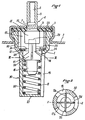
- La figure 1 est une vue en coupe axiale d'une valve selon l'invention suivant la ligne I-I de la figure 2 ; et
- la figure 2 est une vue en coupe perpendiculaire à l'axe de la même valve, suivant la ligne 11-11 de la figure 1.
- Figure 1 is an axial sectional view of a valve according to the invention along line II of Figure 2; and
- FIG. 2 is a sectional view perpendicular to the axis of the same valve, along line 11-11 of FIG. 1.
La valve selon l'invention, prévue pour être fixée dans l'ouverture d'un récipient tel qu'une bouteille ou analogue, comporte un corps de calve 1 fixé dans une capsule 2 avec interposition d'un joint annulaire 3. La capsule 2 est elle-même sertie sur le col d'un récipient, non représenté, avec interposition d'un autre joint, de façon bien connue. Un tel récipient est prévu pour contenir un produit liquide, avec un gaz sous pression (dit propulseur) soluble dans le produit. Le principe de fonctionnement d'une telle valve doseuse est bien connu. Il est décrit dans les brevets cités ci-dessus. Le corps de valve forme à sa partie supérieure une chambre de mesure 13 et à sa partie inférieure un logement 30 pour un ressort de rappel. Les mots supérieure, inférieure, haut ou bas concernent la position droite du récipient, avec l'ouverture vers le haut. Il est entendu que le récipient doit être renversé pour fonctionner. A l'intérieur du corps de valve est disposée une tige de soupape 4 dont une partie 5 s'étend à l'extérieur, à travers le joint 3. Cette tige comporte un canal axial ou longitudinal 6 débouchant à l'extrémité extérieure de la tige et communiquant avec un passage radial 7. La tige 4 est repoussée vers le haut par un ressort 8 et vient prendre appui contre le joint 3 par un épaulement 9. Dans la position de repos, ressort détendu, avec l'épaulement 9 contre le joint 3, le passage 7 débouche au-dessus du joint (éventuellement dans le joint, mais pas en dessous) de sorte que le flacon est fermé, et le produit sous pression ne peut sortir. La tige 4 se prolonge dans l'intérieur du récipient par une partie élargie ou piston 11, par exemple de même diamètre que l'épaulement 9, et un joint annulaire 12 est disposé à une certaine distance du piston, l'ouverture centrale 31 du joint 12 correspondant au diamètre du piston 11. Pour faire sortir une dose du produit, on retourne le récipient, en plaçant l'ouverture avec la valve en bas.The valve according to the invention, intended to be fixed in the opening of a container such as a bottle or the like, comprises a
Quand on enfonce la tige 4 contre la force du ressort 8, au moyen d'un bouton poussoir non représenté, le piston 11 vient obturer l'ouverture du joint 12 avant que l'ouverture du passage 7 n'apparaisse sur la face inférieure du joint 3. On forme ainsi un volume fermé, ou chambre 13, qui contient une dose, dont le volume est déterminé de façon précise, du produit à pulvériser chargé de gaz propulseur dissout sous pression. Quand on continue à enfoncer la tige 4 contre la force du ressort 8, l'ouverture du passage 7 apparaît dans la chambre 13, et le contenu de celle-ci est alors évacué par le passage 7 et le canal 6, sous l'effet du gaz propulseur qui se dégage par suite de la chute de la pression. Après avoir fait sortir une dose, on libère la tige 4 qui est renvoyée à sa position initiale par le ressort de rappel 8. La chambre 13 est alors ouverte. Pour recharger la chambre de dosage, il faut tenir le récipient renversé.When the rod 4 is pressed against the force of the
Comme dans le brevet français 1 287 373 mentionné ci-dessus, le produit parvient dans la chambre 13 par au moins une ouverture prévue dans le bas du corps de valve, en dessous du joint 12. Au-delà du piston 11, la tige 4 se prolonge avantageusement par une partie amincie 14 présentant par exemple un épaulement 15 pour l'appui du ressort. La tige 4 se termine par un fût 16 engagé entre les spires du ressort et servant au guidage et au centrage de la tige 4. La partie amincie 14 a des dimensions telles qu'en position de repos, le piston 11 étant dégagé du joint 12, le produit puisse parvenir facilement dans la chambre 13.As in the
Conformément à une caractéristique de la présente invention, la partie amincie 14 est constituée de plusieurs nervures radiales 17a, 17b, 17c, 17d etc, de section constante ou non et s'étendant depuis le piston 11 jusqu'à l'épaulement 15. Avantageusement, chaque nervure a la forme bien visible sur la figure 1. Cette disposition présente l'avantage de laisser un passage important pour le produit tant lors du remplissage initial du flacon que lors de l'emploi normal. Les nervures 17 maintiennent en outre l'ouverture du joint si celui-ci venait à gonfler sous l'influence du produit mis en circulation. En combinaison avec cette forme de la tige, le bas du corps de valve forme un logement 30 pour le ressort, et ce logement comporte des ouvertures 19 s'étendant sur toute la hauteur disponible, c'est-à-dire depuis un point voisin du joint 12, en dessous de celui-ci, pratiquement jusqu'au fond du logement 30 du ressort, le nombre des ouvertures 19 étant différent du nombre des nervures 17, de façon à avoir toujours au moins un passage continu dégagé, en évitant qu'il y ait une nervure en face de chaque ouverture.According to a characteristic of the present invention, the
Avantageusement, il y a quatre nervures 17 et trois ouvertures 19, séparées par des parois 20 réunies par un fond 21.Advantageously, there are four ribs 17 and three
Selon une autre caractéristique de la présente invention, la tige de soupape 4 est en deux pièces : une première pièce supérieure 32 constituée par la partie extérieure 5 et le piston 11, et une deuxième pièce 33 constituée par la partie amincie 14, l'épaulement 15 et le fût 16. Les deux pièces ainsi constituées sont plus faciles à fabriquer, avec plus de précision, en évitant le moulage en coquille. Les deux pièces peuvent être assemblées par tout moyen : emboîtement à force, avec ou sans colle (comme indiqué par la ligne pointillée 29), vissage, soudure, etc.According to another characteristic of the present invention, the valve stem 4 is in two parts: a first
Afin de maintenir le joint 12 dans son logement, on peut prévoir une pièce d'écartement 23 (moitié droite de la figure 1), prenant appui d'un côté sur le joint 3, de l'autre sur .le joint 12 et sur un épaulement 24 du corps de valve 1, ce qui limite le serrage du joint 12.In order to keep the
Pour empêcher les joints de glisser lors du remplissage, on prévoit des pointes 25, sur le corps de valve 1 et/ou sur la pièce d'écartement 23.To prevent the seals from sliding during filling,
En l'absence de la pièce d'écartement 23, le corps de valve 1 peut présenter des nervures radiales 26 (moitié gauche de la figure 1) qui renforcent mécaniquement la chambre, surtout quand elle est très creuse, pour expulser des grandes doses. Les nervures servent également à maintenir en place le joint 12. En supprimant la déformation de la chambre, la présence des nervures permet d'avoir des doses plus précises.In the absence of the
Claims (2)
Priority Applications (1)
| Application Number | Priority Date | Filing Date | Title |
|---|---|---|---|
| AT82400566T ATE8235T1 (en) | 1981-03-30 | 1982-03-29 | METERING VALVE FOR AEROSOL CANS WITH REVERSE POSITION DELIVERY. |
Applications Claiming Priority (2)
| Application Number | Priority Date | Filing Date | Title |
|---|---|---|---|
| FR8106272 | 1981-03-30 | ||
| FR8106272A FR2502732B1 (en) | 1981-03-30 | 1981-03-30 | REVERSE POSITIONING VALVE FOR AEROSOL CONTAINER |
Publications (2)
| Publication Number | Publication Date |
|---|---|
| EP0061973A1 EP0061973A1 (en) | 1982-10-06 |
| EP0061973B1 true EP0061973B1 (en) | 1984-07-04 |
Family
ID=9256749
Family Applications (1)
| Application Number | Title | Priority Date | Filing Date |
|---|---|---|---|
| EP82400566A Expired EP0061973B1 (en) | 1981-03-30 | 1982-03-29 | Metering valve operating in inverted position, for an aerosol container |
Country Status (6)
| Country | Link |
|---|---|
| US (1) | US4413755A (en) |
| EP (1) | EP0061973B1 (en) |
| AT (1) | ATE8235T1 (en) |
| DE (1) | DE3260319D1 (en) |
| ES (1) | ES272070Y (en) |
| FR (1) | FR2502732B1 (en) |
Cited By (2)
| Publication number | Priority date | Publication date | Assignee | Title |
|---|---|---|---|---|
| US7234460B2 (en) | 2002-09-06 | 2007-06-26 | 3M Innovative Properties Company | Metering valve for a metered dose inhaler providing consistent delivery |
| US7299801B2 (en) | 2002-09-06 | 2007-11-27 | 3M Innovative Properties Company | Metering valve for a metered dose inhaler providing consistent delivery |
Families Citing this family (33)
| Publication number | Priority date | Publication date | Assignee | Title |
|---|---|---|---|---|
| GB8330851D0 (en) * | 1983-11-18 | 1983-12-29 | Fisons Plc | Device |
| GB8503553D0 (en) * | 1985-02-12 | 1985-03-13 | Bespak Plc | Valves for pressurised dispensing containers |
| US4819834A (en) * | 1986-09-09 | 1989-04-11 | Minnesota Mining And Manufacturing Company | Apparatus and methods for delivering a predetermined amount of a pressurized fluid |
| FR2615172B1 (en) * | 1987-05-11 | 1989-08-18 | Valois | DOSER AEROSOL VALVE FOR USE IN THE REVERSE POSITION |
| FR2615173B1 (en) * | 1987-05-13 | 1989-08-18 | Valois | DOSING VALVE FOR LIQUID LOADED WITH A LIQUID OR LIQUEFIED GAS PROPELLER, FOR USE IN THE REVERSE POSITION |
| US5231983A (en) * | 1990-01-03 | 1993-08-03 | Minnesota Mining And Manufacturing | Method of and apparatus for the aerosol administration of medication |
| DE69430303T2 (en) * | 1991-03-05 | 2002-11-28 | Aradigm Corp | METHOD AND DEVICE FOR CORRECTING A ZERO SIGNAL OF A PRESSURE SENSOR FOR A FLOW METER |
| US5392768A (en) * | 1991-03-05 | 1995-02-28 | Aradigm | Method and apparatus for releasing a controlled amount of aerosol medication over a selectable time interval |
| US5404871A (en) * | 1991-03-05 | 1995-04-11 | Aradigm | Delivery of aerosol medications for inspiration |
| US5394866A (en) * | 1991-03-05 | 1995-03-07 | Aradigm Corporation | Automatic aerosol medication delivery system and methods |
| US5450336A (en) * | 1991-03-05 | 1995-09-12 | Aradigm Corporation | Method for correcting the drift offset of a transducer |
| GB2311982B (en) * | 1996-04-09 | 2000-03-08 | Bespak Plc | Improvements in or relating to valves for dispensers |
| US6092698A (en) * | 1999-03-30 | 2000-07-25 | Precision Valve Corporation | High volume aerosol valve |
| FR2798367B1 (en) * | 1999-09-15 | 2001-11-23 | Valois Sa | VALVE GASKET FOR DOSING VALVE |
| CA2469312A1 (en) * | 2001-12-31 | 2003-07-31 | 3M Innovative Properties Company | Valve stem for use in a metering valve |
| EP1461269A1 (en) * | 2001-12-31 | 2004-09-29 | 3M Innovative Properties Company | Gasket for use in a metering valve that limits seal intrusion |
| US6832704B2 (en) | 2002-06-17 | 2004-12-21 | Summit Packaging Systems, Inc. | Metering valve for aerosol container |
| DE10229185A1 (en) * | 2002-06-28 | 2004-02-05 | Thomas Gmbh | pressure regulating valve |
| WO2004041340A2 (en) * | 2002-10-30 | 2004-05-21 | Nektar Therapeutics | Increased dosage metered dose inhaler |
| DE102004034626A1 (en) * | 2004-06-17 | 2006-01-12 | Seaquist Perfect Dispensing Gmbh | Dosing valve and device for dispensing a preferably cosmetic liquid |
| GB0505082D0 (en) * | 2005-03-11 | 2005-04-20 | Alticosalian Gerald H | A device for storing and dispensing liquid |
| FR2888822B1 (en) * | 2005-07-21 | 2010-04-02 | Valois Sas | FLUID PRODUCT DELIVERY VALVE |
| FR2917073B1 (en) * | 2007-06-11 | 2012-10-05 | Valois Sas | FLUID PRODUCT DISPENSING VALVE AND FLUID PRODUCT DISPENSING DEVICE COMPRISING SUCH A VALVE |
| US9242256B2 (en) * | 2007-07-17 | 2016-01-26 | S.C. Johnson & Son, Inc. | Aerosol dispenser assembly having VOC-free propellant and dispensing mechanism therefor |
| GB0719416D0 (en) * | 2007-10-05 | 2007-11-14 | 3M Innovative Properties Co | Metered dose valve |
| FR2924101B1 (en) * | 2007-11-26 | 2009-12-04 | Valois Sas | IMPROVED VALVE |
| US8087548B2 (en) * | 2008-05-14 | 2012-01-03 | S.C. Johnson & Son, Inc. | Spray products with particles and improved valve for inverted dispensing without clogging |
| FR3049275B1 (en) * | 2016-03-23 | 2019-07-19 | Aptar France Sas | DOSING VALVE AND DEVICE FOR DISPENSING FLUID PRODUCT COMPRISING SUCH A VALVE |
| GB201702407D0 (en) | 2017-02-14 | 2017-03-29 | Norton (Waterford) Ltd | Inhalers and related methods |
| GB201702406D0 (en) | 2017-02-14 | 2017-03-29 | Norton (Waterford) Ltd | Inhalers and related methods |
| GB201702408D0 (en) | 2017-02-14 | 2017-03-29 | Norton (Waterford) Ltd | Inhalers and related methods |
| FR3065891B1 (en) * | 2017-05-05 | 2021-12-24 | Aptar France Sas | METERING VALVE AND FLUID PRODUCT DISTRIBUTION DEVICE COMPRISING SUCH A VALVE. |
| FR3131738B1 (en) * | 2022-01-07 | 2024-03-08 | Aptar France Sas | Dosing valve with improved dosing chamber |
Family Cites Families (9)
| Publication number | Priority date | Publication date | Assignee | Title |
|---|---|---|---|---|
| US2886217A (en) * | 1957-05-20 | 1959-05-12 | Riker Laboratories Inc | Dispensing device |
| FR1292114A (en) * | 1961-06-14 | 1962-04-27 | C I M A Costruzione Impianti E | Push-button metering valve for the release of liquids under pressure |
| US3332626A (en) * | 1965-06-21 | 1967-07-25 | Meshberg Philip | Dispensing valve |
| US3394851A (en) * | 1965-09-20 | 1968-07-30 | Sterling Drug Inc | Metered aerosol valve for use with compressed gas |
| US3447551A (en) * | 1967-06-14 | 1969-06-03 | Arthur R Braun | Upside-downside aerosol dispensing valve |
| US3521859A (en) * | 1968-05-31 | 1970-07-28 | Erich W Gronemeyer | Valve |
| US3511418A (en) * | 1968-07-29 | 1970-05-12 | Risdon Mfg Co | Variable capacity aerosol metering valve |
| US3591059A (en) * | 1969-03-10 | 1971-07-06 | Riker Laboratories Inc | Metering valve with air shutoff |
| GB2086845B (en) * | 1977-09-22 | 1982-12-08 | Glaxo Group Ltd | Metering valve |
-
1981
- 1981-03-30 FR FR8106272A patent/FR2502732B1/en not_active Expired
-
1982
- 1982-03-29 ES ES1982272070U patent/ES272070Y/en not_active Expired
- 1982-03-29 DE DE8282400566T patent/DE3260319D1/en not_active Expired
- 1982-03-29 EP EP82400566A patent/EP0061973B1/en not_active Expired
- 1982-03-29 AT AT82400566T patent/ATE8235T1/en not_active IP Right Cessation
- 1982-03-30 US US06/363,748 patent/US4413755A/en not_active Expired - Lifetime
Cited By (3)
| Publication number | Priority date | Publication date | Assignee | Title |
|---|---|---|---|---|
| US7234460B2 (en) | 2002-09-06 | 2007-06-26 | 3M Innovative Properties Company | Metering valve for a metered dose inhaler providing consistent delivery |
| US7299801B2 (en) | 2002-09-06 | 2007-11-27 | 3M Innovative Properties Company | Metering valve for a metered dose inhaler providing consistent delivery |
| US7748378B2 (en) | 2002-09-06 | 2010-07-06 | 3M Innovative Properties Company | Metering valve for a metered dose inhaler providing consistent delivery |
Also Published As
| Publication number | Publication date |
|---|---|
| ES272070Y (en) | 1984-04-16 |
| DE3260319D1 (en) | 1984-08-09 |
| US4413755A (en) | 1983-11-08 |
| ES272070U (en) | 1983-10-16 |
| ATE8235T1 (en) | 1984-07-15 |
| EP0061973A1 (en) | 1982-10-06 |
| FR2502732A1 (en) | 1982-10-01 |
| FR2502732B1 (en) | 1985-08-30 |
Similar Documents
| Publication | Publication Date | Title |
|---|---|---|
| EP0061973B1 (en) | Metering valve operating in inverted position, for an aerosol container | |
| EP0694483B1 (en) | Container for the storage of at least two products, and for the mixture and distribution of these products | |
| EP0549049B1 (en) | Assembly for dispensing at least one fluid product | |
| EP0551782B1 (en) | Metering valve that can be utilised in an inverted position | |
| EP0937505B1 (en) | Packaging and dispensing unit and use of such a unit for packaging cosmetical, pharmaceutical or dermopharmaceutical products | |
| EP0626210B1 (en) | Dispensing device for a metered volume dose of a liquid or pasty product | |
| EP1044893B1 (en) | Device for the extemporaneous mixture of at least two products, of which one is a powder | |
| CA2163357C (en) | Metering device for dispensing constant unit doses | |
| CA2262135C (en) | Packaging and dispenser presentation for a liquid product | |
| FR2615173A1 (en) | DOSING VALVE FOR LIQUID LOADED WITH A LIQUID OR LIQUEFIED GAS PROPELLER, FOR USE IN THE REVERSE POSITION | |
| EP0526811B1 (en) | Storage and distribution device for liquid or pasty products | |
| EP0823389B1 (en) | Pressurised device with a slit element of foam material as pressurising means | |
| FR2640942A1 (en) | Container of the aerosol type for delivering, in the form of a foam, metered quantities of product, particularly of food product | |
| CH422561A (en) | Dispenser-doser | |
| FR2559567A1 (en) | DOSING VALVE FOR CONTAINER CONTAINING A PRESSURIZED PRODUCT | |
| EP0406134A1 (en) | Container with elastic bottle | |
| EP0312474B1 (en) | Automatic dispenser for viscous products | |
| EP0591043A1 (en) | Aerosol type packaging container refillable with compressed gas | |
| FR2757487A1 (en) | STACKABLE PRESSURE FLUID BOX | |
| FR2541244A1 (en) | Device for dispensing metered quantities of liquid substance | |
| EP0605275B1 (en) | Assembly for spraying a liquid comprising a precompression pump | |
| EP0444990B1 (en) | Dispensing device for liquid or pasty products, particularly for cosmetic products | |
| CH545730A (en) | Two part prepn storage container - esp for pharmaceuticals with components separately stored until required for use | |
| FR2731684A1 (en) | DEVICE FOR STORING AND DISPENSING A PRODUCT, SUCH AS A COSMETIC PRODUCT OR A PERFUME | |
| BE682750A (en) |
Legal Events
| Date | Code | Title | Description |
|---|---|---|---|
| PUAI | Public reference made under article 153(3) epc to a published international application that has entered the european phase |
Free format text: ORIGINAL CODE: 0009012 |
|
| AK | Designated contracting states |
Designated state(s): AT BE CH DE GB IT NL SE |
|
| 17P | Request for examination filed |
Effective date: 19821014 |
|
| ITF | It: translation for a ep patent filed | ||
| GRAA | (expected) grant |
Free format text: ORIGINAL CODE: 0009210 |
|
| AK | Designated contracting states |
Designated state(s): AT BE CH DE GB IT LI NL SE |
|
| REF | Corresponds to: |
Ref document number: 8235 Country of ref document: AT Date of ref document: 19840715 Kind code of ref document: T |
|
| REF | Corresponds to: |
Ref document number: 3260319 Country of ref document: DE Date of ref document: 19840809 |
|
| PLBE | No opposition filed within time limit |
Free format text: ORIGINAL CODE: 0009261 |
|
| STAA | Information on the status of an ep patent application or granted ep patent |
Free format text: STATUS: NO OPPOSITION FILED WITHIN TIME LIMIT |
|
| 26N | No opposition filed | ||
| PGFP | Annual fee paid to national office [announced via postgrant information from national office to epo] |
Ref country code: AT Payment date: 19900222 Year of fee payment: 9 |
|
| PGFP | Annual fee paid to national office [announced via postgrant information from national office to epo] |
Ref country code: BE Payment date: 19900228 Year of fee payment: 9 |
|
| PGFP | Annual fee paid to national office [announced via postgrant information from national office to epo] |
Ref country code: CH Payment date: 19900312 Year of fee payment: 9 |
|
| PGFP | Annual fee paid to national office [announced via postgrant information from national office to epo] |
Ref country code: SE Payment date: 19900327 Year of fee payment: 9 |
|
| ITTA | It: last paid annual fee | ||
| PGFP | Annual fee paid to national office [announced via postgrant information from national office to epo] |
Ref country code: NL Payment date: 19900331 Year of fee payment: 9 |
|
| PG25 | Lapsed in a contracting state [announced via postgrant information from national office to epo] |
Ref country code: AT Effective date: 19910329 |
|
| PG25 | Lapsed in a contracting state [announced via postgrant information from national office to epo] |
Ref country code: SE Effective date: 19910330 |
|
| PG25 | Lapsed in a contracting state [announced via postgrant information from national office to epo] |
Ref country code: LI Effective date: 19910331 Ref country code: CH Effective date: 19910331 Ref country code: BE Effective date: 19910331 |
|
| BERE | Be: lapsed |
Owner name: ETS VALOIS Effective date: 19910331 |
|
| PG25 | Lapsed in a contracting state [announced via postgrant information from national office to epo] |
Ref country code: NL Effective date: 19911001 |
|
| NLV4 | Nl: lapsed or anulled due to non-payment of the annual fee | ||
| REG | Reference to a national code |
Ref country code: CH Ref legal event code: PL |
|
| EUG | Se: european patent has lapsed |
Ref document number: 82400566.4 Effective date: 19911009 |
|
| PGFP | Annual fee paid to national office [announced via postgrant information from national office to epo] |
Ref country code: GB Payment date: 20010222 Year of fee payment: 20 |
|
| PGFP | Annual fee paid to national office [announced via postgrant information from national office to epo] |
Ref country code: DE Payment date: 20010313 Year of fee payment: 20 |
|
| REG | Reference to a national code |
Ref country code: GB Ref legal event code: IF02 |
|
| PG25 | Lapsed in a contracting state [announced via postgrant information from national office to epo] |
Ref country code: GB Free format text: LAPSE BECAUSE OF EXPIRATION OF PROTECTION Effective date: 20020328 |
|
| REG | Reference to a national code |
Ref country code: GB Ref legal event code: PE20 Effective date: 20020326 |