EP0061979A1 - Einspritzsysteme mit vorgesteuertem Einspritzventil für Verbrennungsmotoren - Google Patents
Einspritzsysteme mit vorgesteuertem Einspritzventil für Verbrennungsmotoren Download PDFInfo
- Publication number
- EP0061979A1 EP0061979A1 EP82420032A EP82420032A EP0061979A1 EP 0061979 A1 EP0061979 A1 EP 0061979A1 EP 82420032 A EP82420032 A EP 82420032A EP 82420032 A EP82420032 A EP 82420032A EP 0061979 A1 EP0061979 A1 EP 0061979A1
- Authority
- EP
- European Patent Office
- Prior art keywords
- chamber
- injector
- piston
- needle
- pressure
- Prior art date
- Legal status (The legal status is an assumption and is not a legal conclusion. Google has not performed a legal analysis and makes no representation as to the accuracy of the status listed.)
- Granted
Links
- 238000002347 injection Methods 0.000 title claims abstract description 41
- 239000007924 injection Substances 0.000 title claims abstract description 41
- 238000002485 combustion reaction Methods 0.000 title claims description 6
- 239000000446 fuel Substances 0.000 claims description 28
- 239000007788 liquid Substances 0.000 claims description 4
- 240000007594 Oryza sativa Species 0.000 claims 1
- 235000007164 Oryza sativa Nutrition 0.000 claims 1
- 235000009566 rice Nutrition 0.000 claims 1
- 238000004891 communication Methods 0.000 abstract description 6
- 239000012530 fluid Substances 0.000 abstract 2
- 238000007789 sealing Methods 0.000 description 3
- 210000000056 organ Anatomy 0.000 description 2
- 239000004215 Carbon black (E152) Substances 0.000 description 1
- 230000003042 antagnostic effect Effects 0.000 description 1
- POIUWJQBRNEFGX-XAMSXPGMSA-N cathelicidin Chemical compound C([C@@H](C(=O)N[C@@H](CCCNC(N)=N)C(=O)N[C@@H](CCCCN)C(=O)N[C@@H](CO)C(=O)N[C@@H](CCCCN)C(=O)N[C@@H](CCC(O)=O)C(=O)N[C@@H](CCCCN)C(=O)N[C@@H]([C@@H](C)CC)C(=O)NCC(=O)N[C@@H](CCCCN)C(=O)N[C@@H](CCC(O)=O)C(=O)N[C@@H](CC=1C=CC=CC=1)C(=O)N[C@@H](CCCCN)C(=O)N[C@@H](CCCNC(N)=N)C(=O)N[C@@H]([C@@H](C)CC)C(=O)N[C@@H](C(C)C)C(=O)N[C@@H](CCC(N)=O)C(=O)N[C@@H](CCCNC(N)=N)C(=O)N[C@@H]([C@@H](C)CC)C(=O)N[C@@H](CCCCN)C(=O)N[C@@H](CC(O)=O)C(=O)N[C@@H](CC=1C=CC=CC=1)C(=O)N[C@@H](CC(C)C)C(=O)N[C@@H](CCCNC(N)=N)C(=O)N[C@@H](CC(N)=O)C(=O)N[C@@H](CC(C)C)C(=O)N[C@@H](C(C)C)C(=O)N1[C@@H](CCC1)C(=O)N[C@@H](CCCNC(N)=N)C(=O)N[C@@H]([C@@H](C)O)C(=O)N[C@@H](CCC(O)=O)C(=O)N[C@@H](CO)C(O)=O)NC(=O)[C@H](CC=1C=CC=CC=1)NC(=O)[C@H](CC(O)=O)NC(=O)CNC(=O)[C@H](CC(C)C)NC(=O)[C@@H](N)CC(C)C)C1=CC=CC=C1 POIUWJQBRNEFGX-XAMSXPGMSA-N 0.000 description 1
- 230000006866 deterioration Effects 0.000 description 1
- 238000005553 drilling Methods 0.000 description 1
- 229930195733 hydrocarbon Natural products 0.000 description 1
- 150000002430 hydrocarbons Chemical class 0.000 description 1
- 238000003754 machining Methods 0.000 description 1
- 238000000034 method Methods 0.000 description 1
Images

Classifications
-
- F—MECHANICAL ENGINEERING; LIGHTING; HEATING; WEAPONS; BLASTING
- F02—COMBUSTION ENGINES; HOT-GAS OR COMBUSTION-PRODUCT ENGINE PLANTS
- F02M—SUPPLYING COMBUSTION ENGINES IN GENERAL WITH COMBUSTIBLE MIXTURES OR CONSTITUENTS THEREOF
- F02M47/00—Fuel-injection apparatus operated cyclically with fuel-injection valves actuated by fluid pressure
- F02M47/02—Fuel-injection apparatus operated cyclically with fuel-injection valves actuated by fluid pressure of accumulator-injector type, i.e. having fuel pressure of accumulator tending to open, and fuel pressure in other chamber tending to close, injection valves and having means for periodically releasing that closing pressure
-
- F—MECHANICAL ENGINEERING; LIGHTING; HEATING; WEAPONS; BLASTING
- F02—COMBUSTION ENGINES; HOT-GAS OR COMBUSTION-PRODUCT ENGINE PLANTS
- F02M—SUPPLYING COMBUSTION ENGINES IN GENERAL WITH COMBUSTIBLE MIXTURES OR CONSTITUENTS THEREOF
- F02M63/00—Other fuel-injection apparatus having pertinent characteristics not provided for in groups F02M39/00 - F02M57/00 or F02M67/00; Details, component parts, or accessories of fuel-injection apparatus, not provided for in, or of interest apart from, the apparatus of groups F02M39/00 - F02M61/00 or F02M67/00; Combination of fuel pump with other devices, e.g. lubricating oil pump
- F02M63/02—Fuel-injection apparatus having several injectors fed by a common pumping element, or having several pumping elements feeding a common injector; Fuel-injection apparatus having provisions for cutting-out pumps, pumping elements, or injectors; Fuel-injection apparatus having provisions for variably interconnecting pumping elements and injectors alternatively
- F02M63/0205—Fuel-injection apparatus having several injectors fed by a common pumping element, or having several pumping elements feeding a common injector; Fuel-injection apparatus having provisions for cutting-out pumps, pumping elements, or injectors; Fuel-injection apparatus having provisions for variably interconnecting pumping elements and injectors alternatively for cutting-out pumps or injectors in case of abnormal operation of the engine or the injection apparatus, e.g. over-speed, break-down of fuel pumps or injectors ; for cutting-out pumps for stopping the engine
-
- F—MECHANICAL ENGINEERING; LIGHTING; HEATING; WEAPONS; BLASTING
- F02—COMBUSTION ENGINES; HOT-GAS OR COMBUSTION-PRODUCT ENGINE PLANTS
- F02B—INTERNAL-COMBUSTION PISTON ENGINES; COMBUSTION ENGINES IN GENERAL
- F02B1/00—Engines characterised by fuel-air mixture compression
- F02B1/02—Engines characterised by fuel-air mixture compression with positive ignition
- F02B1/04—Engines characterised by fuel-air mixture compression with positive ignition with fuel-air mixture admission into cylinder
-
- F—MECHANICAL ENGINEERING; LIGHTING; HEATING; WEAPONS; BLASTING
- F02—COMBUSTION ENGINES; HOT-GAS OR COMBUSTION-PRODUCT ENGINE PLANTS
- F02B—INTERNAL-COMBUSTION PISTON ENGINES; COMBUSTION ENGINES IN GENERAL
- F02B75/00—Other engines
- F02B75/12—Other methods of operation
- F02B2075/125—Direct injection in the combustion chamber for spark ignition engines, i.e. not in pre-combustion chamber
-
- F—MECHANICAL ENGINEERING; LIGHTING; HEATING; WEAPONS; BLASTING
- F02—COMBUSTION ENGINES; HOT-GAS OR COMBUSTION-PRODUCT ENGINE PLANTS
- F02B—INTERNAL-COMBUSTION PISTON ENGINES; COMBUSTION ENGINES IN GENERAL
- F02B3/00—Engines characterised by air compression and subsequent fuel addition
- F02B3/06—Engines characterised by air compression and subsequent fuel addition with compression ignition
-
- Y—GENERAL TAGGING OF NEW TECHNOLOGICAL DEVELOPMENTS; GENERAL TAGGING OF CROSS-SECTIONAL TECHNOLOGIES SPANNING OVER SEVERAL SECTIONS OF THE IPC; TECHNICAL SUBJECTS COVERED BY FORMER USPC CROSS-REFERENCE ART COLLECTIONS [XRACs] AND DIGESTS
- Y02—TECHNOLOGIES OR APPLICATIONS FOR MITIGATION OR ADAPTATION AGAINST CLIMATE CHANGE
- Y02T—CLIMATE CHANGE MITIGATION TECHNOLOGIES RELATED TO TRANSPORTATION
- Y02T10/00—Road transport of goods or passengers
- Y02T10/10—Internal combustion engine [ICE] based vehicles
- Y02T10/12—Improving ICE efficiencies
Definitions
- the present invention relates to an injection system intended to equip an internal combustion engine. It is known that the purpose of the injection system is to dose a liquid fuel (in particular a hydrocarbon) before sending it under pressure to an injector.
- a liquid fuel in particular a hydrocarbon
- each combustion chamber is equipped with an injector provided with a shutter needle, which lifts at the start of each injection, to close on his seat as soon as the injection is finished.
- the injector needle is subjected to the thrust of a spring which tends to push it back onto its seat, that is to say to return it to the closed position.
- the pressure wave causes the injector needle to rise.
- the return spring tends to close the needle, and it effectively closes it most of the time.
- the needle tends to seize up in the injector body, so that the spring return thrust becomes insufficient to close the needle. Communication then remains established between the body of the injector holder and the combustion chamber, which has the result of causing the engine to break down more or less quickly. This drawback is particularly serious in the case of an injection system with constant pressure supply, because then the open seized injector continuously delivers fuel.
- the object of the present invention is to avoid this drawback by providing a safety system which automatically cuts off the supply of an injector when the latter remains seized in the open position.
- a safety device intended to equip the injector with an internal combustion engine provided with a needle normally driven by a lifting and falling movement, respectively at the start and at the end of each injection, while supply piping supplies the injector with liquid fuel at the supply pressure, and characterized in that dispensing means receiving the fuel at the supply pressure are provided on a part integral with the injector needle 4 to move in front a fixed orifice of the injector holder 1 which communicates with a chamber 13 with an obturator piston to admit fuel therein through the dispensing means when the injector needle is in the open position, this piston chamber being equipped with a sliding differential piston 13,14 which, when the pressure in its chamber 13 reaches a predetermined threshold, moves to close off the general supply of the injector 2, timed pressure establishment means being finally provided on the chamber 13 the shutter piston.
- the injector needle lifts pressurized fuel begins to enter the chamber of the shutter piston. If this admission does not exceed a predetermined duration, defined by the delay means, the pressure in the chamber of the shutter piston never exceeds its triggering threshold, and nothing happens: the injection is carried out normally, and it ceases as soon as the needle closes.
- the duration threshold defined by the timing means is chosen for a time greater than the duration of the longest injections planned for the system, in order not to hinder in any way a normal injection process.
- the injector needle tends to remain seized in the open position
- the duration increases during which pressurized fuel is admitted into the chamber of the obturator piston.
- the pressure becomes sufficient behind the obturator piston to move it and automatically come to cut the supply of the injector out of order. This cutoff is maintained as long as the injector needle remains seized in the open position. This avoids any serious deterioration of the engine.
- the timer means are constituted by a calibrated orifice equipping the chamber of the shutter piston, to connect it to the fuel discharge circuit.
- the chamber of this shutter piston is therefore supplied through a section orifice S of the dispensing means, and it is connected to the discharge by a section orifice s. It suffices to calculate the relative values of the supply and discharge sections S to define the pressure which builds up behind the obturator piston in the case of a permanent flow, that is to say when the needle of the injector is seized open.
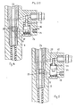
- an injector 2 Inside the injector holder 1 is in the known manner an injector 2, the end of which includes injection 3.
- a sealing seat not shown, on which the end of an injector needle 4 can come in known manner.
- the tail 5 of the injector needle 4 receives an end piece 6 behind which bears a calibrated return spring 7.
- the end piece 6 is part of a pusher 8 which, according to the invention, has a rear cylindrical part 9 playing the role of a hydraulic distributor.
- the needle 4 lifts with each injection and the result for the drawer 9 is an alternating sliding movement in a stationary distributor body 10.
- the clearance between the drawer 9 and the body 10 corresponds to tolerances common machining operations on injection systems, to ensure satisfactory sealing of the combustible liquid when the latter is at the usual pressure,
- the dispenser drawer 9 has a groove ll which is capable of moving in front of a fixed orifice 12 which has a passage section of value S.
- This orifice 12 is formed in the body 10 and it communicates with a cylindrical chamber 13 in which can slide sealingly a differential piston comprising a large section 14 and a small section 15.
- the large section body 14 of this piston 14, 15 slides in the cylindrical chamber 13 between a return spring 16 and an antagonistic thrust coming from the fuel admitted by orifice 12.
- the small section 15 is that of a cylindrical rod sliding in leaktight manner in a fixed cylindrical bore 19.
- the latter is arranged across a supply channel 20 that the small section 15 is completely closed when the differential piston 15, 16 occupies the raised position illustrated in FIG. 5.
- a nozzle 21 with calibrated section also connects the chamber 13 to a discharge circuit, not shown, which returns the fuel to the tank.
- the chamber located around the return spring 16 is also connected by a leak orifice 22, to the discharge circuit returning the fuel to the tank.
- the channel 20 receives in the known manner the main flow of fuel from the high pressure pump of the injection circuit.
- This channel 20 communicates in the usual way by holes such as 23 provided in the body of the injector holder 1, with the injection chamber not shown which is behind the sealing seat, at the end of the needle 4, for injecting the fuel into the engine by the orifices 3, as soon as the needle 4 is raised.
- a bore 25 is provided on the rear of the distributor drawer 9 which places the groove 11 in communication with the axial bore 24.
- the set of two calibrated orifices 12 (section S) and 21 (section s) constitutes a timer means for the operation of which S is given a value greater than that. from s.
- the law of this rise in pressure in the chamber 13 in function of time can be defined at will by the initial choice of the relative value of sections S and s.
- the respective values of S and s are chosen so that the pressure build-up in the chamber 13 of the differential piston 14,15 is sufficiently slow not to become preponderant compared to the setting thrust of the spring 16, for a period of time. less equal to the longest possible duration of an injection according to the various possible engine operating conditions.
- the differential piston 14, 15 remains constantly stationary in the position illustrated in FIG. 4, as long as the needle 4 of the injector operates in a normal manner. Indeed, at each start of injection, the needle 4 is raised, the groove 11 comes into coincidence with the orifice 12, and the pressure begins to rise in the chamber 13. However, before this pressure has enough mounted to crush the spring 16 and move the obturator piston 14,15, the injection ended, and the needle 4 fell back on its seat, the groove 11 returning to the position of Figure 2, which cuts the 'supply of the orifice 12. The chamber 13 now ceasing to be supplied while the nozzle 21 connects it to the discharge, its pressure drops and the differential piston 14, 15, remains stationary.
- the rod with a small section 15 of the differential piston completely closes the pipe 20 ensuring the supply of the injector 2. Consequently, as long as the needle 4 remains open, the supply of fuel stop by the canalisa tions 20, 23. This eliminates the incident which, on a conventional engine, would have led the injector 2 to continuously deliver fuel to the engine.
Landscapes
- Engineering & Computer Science (AREA)
- Chemical & Material Sciences (AREA)
- Combustion & Propulsion (AREA)
- Mechanical Engineering (AREA)
- General Engineering & Computer Science (AREA)
- Physics & Mathematics (AREA)
- Fluid Mechanics (AREA)
- Fuel-Injection Apparatus (AREA)
- Electrical Control Of Air Or Fuel Supplied To Internal-Combustion Engine (AREA)
Priority Applications (1)
| Application Number | Priority Date | Filing Date | Title |
|---|---|---|---|
| AT82420032T ATE12674T1 (de) | 1981-03-26 | 1982-03-12 | Einspritzsysteme mit vorgesteuertem einspritzventil fuer verbrennungsmotoren. |
Applications Claiming Priority (2)
| Application Number | Priority Date | Filing Date | Title |
|---|---|---|---|
| FR8106572A FR2502701A1 (fr) | 1981-03-26 | 1981-03-26 | Systeme d'injection a pilotage de l'injecteur, pour un moteur a combustion interne |
| FR8106572 | 1981-03-26 |
Publications (2)
| Publication Number | Publication Date |
|---|---|
| EP0061979A1 true EP0061979A1 (de) | 1982-10-06 |
| EP0061979B1 EP0061979B1 (de) | 1985-04-10 |
Family
ID=9256894
Family Applications (1)
| Application Number | Title | Priority Date | Filing Date |
|---|---|---|---|
| EP82420032A Expired EP0061979B1 (de) | 1981-03-26 | 1982-03-12 | Einspritzsysteme mit vorgesteuertem Einspritzventil für Verbrennungsmotoren |
Country Status (6)
| Country | Link |
|---|---|
| US (1) | US4467757A (de) |
| EP (1) | EP0061979B1 (de) |
| JP (1) | JPS58117356A (de) |
| AT (1) | ATE12674T1 (de) |
| DE (1) | DE3262934D1 (de) |
| FR (1) | FR2502701A1 (de) |
Cited By (5)
| Publication number | Priority date | Publication date | Assignee | Title |
|---|---|---|---|---|
| FR2558533A1 (fr) * | 1984-01-23 | 1985-07-26 | Renault | Dispositif de securite pour soupape d'injection de moteur a combustion interne |
| EP0385399A3 (de) * | 1989-03-03 | 1991-06-19 | ELASIS SISTEMA RICERCA FIAT NEL MEZZOGIORNO Società Consortile per Azioni | Elektromagnetischer Kraftstoffinjektor eines Dieselmotors |
| FR2665930A1 (fr) * | 1990-08-17 | 1992-02-21 | Daimler Benz Ag | Systeme d'injection a pompe et injecteur et commande par electrovanne pour moteur a combustion interne avec compression d'air. |
| FR2756013A1 (fr) * | 1996-11-15 | 1998-05-22 | Daimler Benz Ag | Installation d'injection de carburant pour un moteur a combustion interne |
| FR2759740A1 (fr) * | 1997-02-19 | 1998-08-21 | Daimler Benz Ag | Dispositif d'injection a accumulateur pour moteurs a combustion interne multicylindriques |
Families Citing this family (9)
| Publication number | Priority date | Publication date | Assignee | Title |
|---|---|---|---|---|
| US4539959A (en) * | 1984-02-27 | 1985-09-10 | General Motors Corporation | Fuel injection system with fuel flow limiting valve assembly |
| DE4002206C2 (de) * | 1990-01-26 | 2000-06-15 | Bosch Gmbh Robert | Katalysatorschutzverfahren |
| DE69218326T2 (de) * | 1991-01-14 | 1997-08-28 | Denso Corp | Druckakkumulier-kraftstoffeinspritzvorrichtung |
| US5537972A (en) * | 1994-07-28 | 1996-07-23 | Servojet Electronics Systems | Fuel injection system having a pressure intensifier incorporating an overtravel safety feature |
| DE19717419C1 (de) * | 1997-04-25 | 1998-07-30 | Daimler Benz Ag | Speichereinspritzsystem für eine mehrzylindrige Brennkraftmaschine mit magnetventilgesteuerten Kraftstoffeinspritzventilen |
| EP0961021B1 (de) * | 1998-05-29 | 2004-04-14 | Toyota Jidosha Kabushiki Kaisha | Kraftstoffversorgung für Verbrennungsmotor |
| FR2853358B1 (fr) * | 2003-04-04 | 2005-05-06 | Peugeot Citroen Automobiles Sa | Moteur a combustion interne a essence et a auto-allumage |
| FR2853354B1 (fr) * | 2003-04-04 | 2006-06-09 | Peugeot Citroen Automobiles Sa | Moteur a combustion interne a injection directe d'essence et a allumage commande |
| FR2853356B1 (fr) * | 2003-04-04 | 2006-06-30 | Peugeot Citroen Automobiles Sa | Moteur a combustion interne a essence et a allumage commande comprenant un systeme d'injection a tres haute pression |
Citations (5)
| Publication number | Priority date | Publication date | Assignee | Title |
|---|---|---|---|---|
| FR1555369A (de) * | 1967-03-22 | 1969-01-24 | ||
| US3443760A (en) * | 1967-04-26 | 1969-05-13 | Parker Hannifin Corp | Fail-safe fuel injection nozzle |
| FR2125946A5 (de) * | 1971-02-19 | 1972-09-29 | Cav Ltd | |
| DE2754615A1 (de) * | 1977-12-08 | 1979-06-13 | Bosch Gmbh Robert | Absperrvorrichtung fuer mindestens ein einspritzventil fuer verbrennungsmotoren |
| GB2051229A (en) * | 1979-06-01 | 1981-01-14 | Maschf Augsburg Nuernberg Ag | Fuel Injection Device for an Internal Combustion Engine |
Family Cites Families (9)
| Publication number | Priority date | Publication date | Assignee | Title |
|---|---|---|---|---|
| US3104817A (en) * | 1963-09-24 | Fuel injector with pilot injection | ||
| US2067997A (en) * | 1934-05-07 | 1937-01-19 | White Eli | Fuel injector for internal combustion engines |
| US2053311A (en) * | 1934-06-13 | 1936-09-08 | Amery George | Fuel and like pump for internal combustion engines |
| US2912168A (en) * | 1956-03-03 | 1959-11-10 | Orange G M B H L | Fuel injection unit |
| US2934138A (en) * | 1958-01-06 | 1960-04-26 | Lucas Industries Ltd | Means for controlling the supply of liquid fuel to a gas turbine |
| US3016838A (en) * | 1959-02-09 | 1962-01-16 | Bessiere Pierre Etienne | Reciprocating action pumps, in particular fuel injection pumps |
| US3645245A (en) * | 1970-09-04 | 1972-02-29 | Caterpillar Tractor Co | Speed limiter for hydraulic governor |
| US3951117A (en) * | 1974-05-30 | 1976-04-20 | Cummins Engine Company, Inc. | Fuel supply system for an internal combustion engine |
| US4369750A (en) * | 1979-12-19 | 1983-01-25 | Cummins Engine Company, Inc. | Fuel injector for internal combustion engine |
-
1981
- 1981-03-26 FR FR8106572A patent/FR2502701A1/fr not_active Withdrawn
-
1982
- 1982-03-12 EP EP82420032A patent/EP0061979B1/de not_active Expired
- 1982-03-12 DE DE8282420032T patent/DE3262934D1/de not_active Expired
- 1982-03-12 AT AT82420032T patent/ATE12674T1/de not_active IP Right Cessation
- 1982-03-23 US US06/361,014 patent/US4467757A/en not_active Expired - Fee Related
- 1982-03-26 JP JP57049929A patent/JPS58117356A/ja active Pending
Patent Citations (5)
| Publication number | Priority date | Publication date | Assignee | Title |
|---|---|---|---|---|
| FR1555369A (de) * | 1967-03-22 | 1969-01-24 | ||
| US3443760A (en) * | 1967-04-26 | 1969-05-13 | Parker Hannifin Corp | Fail-safe fuel injection nozzle |
| FR2125946A5 (de) * | 1971-02-19 | 1972-09-29 | Cav Ltd | |
| DE2754615A1 (de) * | 1977-12-08 | 1979-06-13 | Bosch Gmbh Robert | Absperrvorrichtung fuer mindestens ein einspritzventil fuer verbrennungsmotoren |
| GB2051229A (en) * | 1979-06-01 | 1981-01-14 | Maschf Augsburg Nuernberg Ag | Fuel Injection Device for an Internal Combustion Engine |
Cited By (7)
| Publication number | Priority date | Publication date | Assignee | Title |
|---|---|---|---|---|
| FR2558533A1 (fr) * | 1984-01-23 | 1985-07-26 | Renault | Dispositif de securite pour soupape d'injection de moteur a combustion interne |
| EP0150138A3 (de) * | 1984-01-23 | 1985-09-11 | Regie Nationale Des Usines Renault | Sicherheitsvorrichtung für Gleichdruckeinspritzventil einer Brennkraftmaschine |
| US4589393A (en) * | 1984-01-23 | 1986-05-20 | Regie Nationale Des Usines Renault | Safety device for constant-pressure injection valve of internal combustion engine |
| EP0385399A3 (de) * | 1989-03-03 | 1991-06-19 | ELASIS SISTEMA RICERCA FIAT NEL MEZZOGIORNO Società Consortile per Azioni | Elektromagnetischer Kraftstoffinjektor eines Dieselmotors |
| FR2665930A1 (fr) * | 1990-08-17 | 1992-02-21 | Daimler Benz Ag | Systeme d'injection a pompe et injecteur et commande par electrovanne pour moteur a combustion interne avec compression d'air. |
| FR2756013A1 (fr) * | 1996-11-15 | 1998-05-22 | Daimler Benz Ag | Installation d'injection de carburant pour un moteur a combustion interne |
| FR2759740A1 (fr) * | 1997-02-19 | 1998-08-21 | Daimler Benz Ag | Dispositif d'injection a accumulateur pour moteurs a combustion interne multicylindriques |
Also Published As
| Publication number | Publication date |
|---|---|
| JPS58117356A (ja) | 1983-07-12 |
| DE3262934D1 (en) | 1985-05-15 |
| EP0061979B1 (de) | 1985-04-10 |
| FR2502701A1 (fr) | 1982-10-01 |
| US4467757A (en) | 1984-08-28 |
| ATE12674T1 (de) | 1985-04-15 |
Similar Documents
| Publication | Publication Date | Title |
|---|---|---|
| EP0061979B1 (de) | Einspritzsysteme mit vorgesteuertem Einspritzventil für Verbrennungsmotoren | |
| EP1188974B1 (de) | Selbstreinigende Dosiervorrichtung | |
| EP2964933B1 (de) | Kompakte dosierungsvorrichtung für einen injektor mit zwei brennstoffkreisläufen für eine flugzeugturbomaschine | |
| EP1059952B1 (de) | Inhalationsbetätigte abgabevorrichtung für ein flüssiges produkt | |
| CH644187A5 (fr) | Dispositif d'injection de combustible, notamment pour des moteurs diesel. | |
| FR2474101A1 (fr) | Dispositif d'injection a regeneration, equipe de valves, pour moteur-fusee | |
| CA2345735C (fr) | Dispositif d'injection a usage unique destine a etre pre-rempli | |
| EP0995031B1 (de) | Kraftstoffeinspritzvorrichtung für dieselmotoren | |
| FR2696613A1 (fr) | Torche à plasma d'arc et procédé de mise en Óoeuvre. | |
| FR2816669A1 (fr) | Injecteur commande en pression avec une courbe d'injection optimisee en fonction de la course | |
| EP0271516B1 (de) | Ventil zum verteilen von flüssigkeiten | |
| FR2494344A1 (fr) | Injecteur de carburant pour moteur a combustion interne | |
| EP0493155B1 (de) | Ventil und Verfahren zur Hydraulikkreislaufentlüftung | |
| CA2126803C (fr) | Systeme de connexion electrique | |
| FR2540482A1 (fr) | Pistolet de distribution pour distributeur de liquide a tuyau rempli | |
| EP2283223A1 (de) | Vorrichtung zur aufnahme von unter druck stehendem gas, anordnung von aufnahme- und ausgabevorrichtungen sowie entsprechendes zufuhrsystem | |
| EP1497039B1 (de) | Abgabepumpe für medien | |
| EP3511476B1 (de) | Drückspüler für wasserklosetts mit drucktasten für die betätigung von grösseren und kleineren spülmengen | |
| EP1937983B1 (de) | Ventil mit gedämpftem öffnungssystem | |
| WO2007116148A1 (fr) | Dispositif limiteur de pression | |
| EP1948532B1 (de) | Pumpenauslöse- und -ausgabekopf | |
| FR2465085A1 (fr) | Dispositif d'injection de carburant pour moteurs a combustion interne | |
| FR2563312A1 (fr) | Soupape de reduction de pression | |
| EP0682613B1 (de) | Elektromagnetisch und durch druck betätigbares ventil | |
| FR2612569A1 (fr) | Injecteur-pompe |
Legal Events
| Date | Code | Title | Description |
|---|---|---|---|
| PUAI | Public reference made under article 153(3) epc to a published international application that has entered the european phase |
Free format text: ORIGINAL CODE: 0009012 |
|
| AK | Designated contracting states |
Designated state(s): AT BE CH DE GB IT LU NL SE |
|
| 17P | Request for examination filed |
Effective date: 19821008 |
|
| ITF | It: translation for a ep patent filed | ||
| GRAA | (expected) grant |
Free format text: ORIGINAL CODE: 0009210 |
|
| AK | Designated contracting states |
Designated state(s): AT BE CH DE GB IT LI LU NL SE |
|
| REF | Corresponds to: |
Ref document number: 12674 Country of ref document: AT Date of ref document: 19850415 Kind code of ref document: T |
|
| REF | Corresponds to: |
Ref document number: 3262934 Country of ref document: DE Date of ref document: 19850515 |
|
| PLBE | No opposition filed within time limit |
Free format text: ORIGINAL CODE: 0009261 |
|
| STAA | Information on the status of an ep patent application or granted ep patent |
Free format text: STATUS: NO OPPOSITION FILED WITHIN TIME LIMIT |
|
| PG25 | Lapsed in a contracting state [announced via postgrant information from national office to epo] |
Ref country code: AT Effective date: 19860312 |
|
| PG25 | Lapsed in a contracting state [announced via postgrant information from national office to epo] |
Ref country code: SE Effective date: 19860313 |
|
| PG25 | Lapsed in a contracting state [announced via postgrant information from national office to epo] |
Ref country code: LU Free format text: LAPSE BECAUSE OF NON-PAYMENT OF DUE FEES Effective date: 19860331 Ref country code: LI Effective date: 19860331 Ref country code: CH Effective date: 19860331 Ref country code: BE Effective date: 19860331 |
|
| 26N | No opposition filed | ||
| BERE | Be: lapsed |
Owner name: RENAULT VEHICULES INDUSTRIELS Effective date: 19860331 |
|
| PG25 | Lapsed in a contracting state [announced via postgrant information from national office to epo] |
Ref country code: NL Effective date: 19861001 |
|
| GBPC | Gb: european patent ceased through non-payment of renewal fee | ||
| REG | Reference to a national code |
Ref country code: CH Ref legal event code: PL |
|
| PG25 | Lapsed in a contracting state [announced via postgrant information from national office to epo] |
Ref country code: DE Effective date: 19861202 |
|
| NLV4 | Nl: lapsed or anulled due to non-payment of the annual fee | ||
| PG25 | Lapsed in a contracting state [announced via postgrant information from national office to epo] |
Ref country code: GB Effective date: 19881121 |
|
| EUG | Se: european patent has lapsed |
Ref document number: 82420032.3 Effective date: 19870224 |