EP0061985A2 - Hoisting and handling apparatus - Google Patents
Hoisting and handling apparatus Download PDFInfo
- Publication number
- EP0061985A2 EP0061985A2 EP82450005A EP82450005A EP0061985A2 EP 0061985 A2 EP0061985 A2 EP 0061985A2 EP 82450005 A EP82450005 A EP 82450005A EP 82450005 A EP82450005 A EP 82450005A EP 0061985 A2 EP0061985 A2 EP 0061985A2
- Authority
- EP
- European Patent Office
- Prior art keywords
- mast
- slide
- lifting
- extension
- extensions
- Prior art date
- Legal status (The legal status is an assumption and is not a legal conclusion. Google has not performed a legal analysis and makes no representation as to the accuracy of the status listed.)
- Withdrawn
Links
Images

Classifications
-
- B—PERFORMING OPERATIONS; TRANSPORTING
- B66—HOISTING; LIFTING; HAULING
- B66F—HOISTING, LIFTING, HAULING OR PUSHING, NOT OTHERWISE PROVIDED FOR, e.g. DEVICES WHICH APPLY A LIFTING OR PUSHING FORCE DIRECTLY TO THE SURFACE OF A LOAD
- B66F9/00—Devices for lifting or lowering bulky or heavy goods for loading or unloading purposes
- B66F9/06—Devices for lifting or lowering bulky or heavy goods for loading or unloading purposes movable, with their loads, on wheels or the like, e.g. fork-lift trucks
Definitions
- the present invention relates to a lifting and handling device for placing heavy objects.
- the object of the invention is to overcome the drawbacks described above.
- the invention therefore relates to a lifting and handling device comprising a main mast fixed to a U-shaped structure resting on casters, said mast receiving a slide on which are fixed two beams supporting the load-supporting arms adjustable in width, on the side of the slide opposite that of the support arms a double-acting traction device and cable is attached, the end of the cable being secured to a removable mast head allowing to include or exclude extensions and thereby increase or decrease the height of the mast.
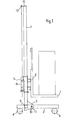
- the lifting and handling device comprises a main mast 1 fixed to a U-shaped structure 2, the connection and the fixing of the mast to the structure being reinforced by a gusset 3 connecting said mast 1 to the cross-member 9 , said gusset being provided with a recess 10 on which is threaded an intermediate cross member 11 serving as a spacer and a handling handle, the structure 2 resting on the rollers 4 to allow its movement.
- a slide 5 On the main mast 1 is slid a slide 5 on the front face of which are fixed two beams 6 on which thread and are held the load support arms 7, the latter being adjustable in width, on the rear face of the slide the cable and double-acting traction device 8 is fixed, the end of the cable 12 being stowed on a removable mast head 13.
- the slide 5 has at its ends 14 and 15 of the front and rear faces a roller 16 rotating on its axis 17 with thread 18 allowing its maintenance by means of nuts 6 on the side faces 19, the ends 14 and 15 being those where the forces due to the load are applied so as to facilitate the displacement of the slide on the mast 1.
- each extension 20 whose section corresponds to the section of the mast 1 is provided in its lower part with an extension 21 added or machined in section allowing it to be fitted over its entire length inside the mast 1 or inside the previous extension 20, at the upper end of the mast 1 or at the upper end of the last extension 20 the removable mast head 13 is fitted, it has an extension 22 of appropriate length and section allowing it to be fitted inside an extension 20 or the mast 1, said mast head 13 being provided with the elements necessary for securing the cable 12 of the traction device 8.
Landscapes
- Engineering & Computer Science (AREA)
- Transportation (AREA)
- Structural Engineering (AREA)
- Civil Engineering (AREA)
- Life Sciences & Earth Sciences (AREA)
- Geology (AREA)
- Mechanical Engineering (AREA)
- Forklifts And Lifting Vehicles (AREA)
- Jib Cranes (AREA)
Abstract
L'invention a pour objet un appareil de levage et manutention comportant une structure en U 2 reposant sur quatre roulettes 4 sur laquelle est fixé un mât 1 servant de guide à un coulisseau 5 relié à un appareil de traction à câble 8, le coulisseau étant doté de deux longerons 6 supportant les bras de soutènement de charge 7 réglables en longueur.
Description
La présente invention est relative à un appareil de levage et manutention pour la mise en place d'objets lourds.The present invention relates to a lifting and handling device for placing heavy objects.
On connaft les appareils de levage et manutention comportant un mât principal sur lequel coulissent les éléments mobiles reliés à un appareil de traction permettant d'élever ou abaisser la charge à déplacer, ce genre d'appareils présente certains inconvénients, ils sont notamment lourds et encombrants, ils ne sont pas démontables, d'autre part afin de raidir et renforcer le mât principal des haubans sont rapportés, il n'est de plus pas possible d'augmenter en hauteur ledit mât.We know the lifting and handling devices comprising a main mast on which slide the mobile elements connected to a traction device for raising or lowering the load to be moved, this type of device has certain disadvantages, they are particularly heavy and bulky , they are not removable, on the other hand in order to stiffen and strengthen the main mast of the shrouds are added, it is also not possible to increase in height said mast.
L'invention a pour but de palier aux inconvénients précédemment exposés.The object of the invention is to overcome the drawbacks described above.
L'invention a en conséquence pour objet un appareil de levage et manutention comportant un mât principal fixé sur une structure en U reposant sur des roulettes, ledit mât recevant un coulisseau sur lequel sont fixés deux longerons supportant les bras de soutènement de la charge réglables en largeur, sur la face du coulisseau opposée à celle des bras de soutènement un appareil de traction à double effet et à câble est fixé, l'extrémité du câble étant arrimée à une tête de mât amovible permettant d'inclure ou d'exclure des ralonges et de ce fait augmenter ou diminuer en hauteur le mât.The invention therefore relates to a lifting and handling device comprising a main mast fixed to a U-shaped structure resting on casters, said mast receiving a slide on which are fixed two beams supporting the load-supporting arms adjustable in width, on the side of the slide opposite that of the support arms a double-acting traction device and cable is attached, the end of the cable being secured to a removable mast head allowing to include or exclude extensions and thereby increase or decrease the height of the mast.
D'autres caractéristiques et avantages de l'invention ressortiront plus clairement de la description qui va suivre faite en regard des dessins joints donnés à titre d'exemple non limitatif, où:
- - la figure 1 est une vue de côté de l'appareil de levage,
- - la figure 2,une vue du coulisseau,
- - la figure 3, une ralonge de mât avec la tête de mât amovible.
- FIG. 1 is a side view of the lifting device,
- FIG. 2, a view of the slide,
- - Figure 3, a mast extension with the removable mast head.
Tel que représenté figure 1, l'appareil de levage et manutention comporte un mât principal 1 fixé sur une structure en U 2, le raccordement et la fixation du mât sur la structure étant renforcés par un gousset 3 reliant ledit mât 1 à la traverse 9, ledit gousset étant pourvu d'un évidement 10 sur lequel s'enfile une traverse intermédiaire 11 servant d'entretoise et de poignée de manutention, la structure 2 reposant sur les roulettes 4 pour permettre son déplacement.As shown in Figure 1, the lifting and handling device comprises a main mast 1 fixed to a U-shaped structure 2, the connection and the fixing of the mast to the structure being reinforced by a gusset 3 connecting said mast 1 to the cross-member 9 , said gusset being provided with a
Sur le mât principal 1 s'enfile un coulisseau 5 sur la face avant duquel sont fixés deux longerons 6 sur lesquels s'enfilent et sont maintenus les bras supports de charge 7, ces derniers étant réglables en'largeur, sur la face arrière du coulisseau est fixé l'appareil de traction à câble et à double effet 8, l'extrémité du câble 12 étant arrimée sur une tête de mât amovible 13.On the main mast 1 is slid a
Tel que représenté figure 2, le coulisseau 5 comporte en ses extrémités 14 et 15 des faces avant et arrière un galet 16 tournant sur son axe 17 doté de filetage 18 permettant son maintien au moyen d'écrous 6 sur les faces latérales 19, les extrémités 14 et 15 étant celles ou sont appliquées les forces dues à la charge de sorte à faciliter le déplacement du coulisseau sur le mât 1.As shown in Figure 2, the
Afin d'augmenter ou réduire la hauteur du mât 1 et comme représenté figure 3 une ou plusieurs ralonges 20 peuvent être ajoutées ou supprimées, chaque ralonge 20 dont la section correspond à la section du mât 1 est pourvue en sa partie inférieure d'un prolongement 21 rapporté ou usiné de section permettant son emboftement sur toute sa longueur à l'intérieur du mât 1 ou à l'intérieur de la ralonge 20 précédente, en l'extrémité supérieure du mât 1 ou en l'extrémité supérieure de la dernière ralonge 20 la tête de mât amovible 13 est emboitée,elle est dotée d'un prolongement 22 de longueur appropriée et de section permettant son emboftement à l'intérieur d'une ralonge 20 ou du mât 1, ladite tête de mât 13 étant pourvue des éléments nécessaires pour l'arrimage du câble 12 de l'appareil de traction 8.In order to increase or reduce the height of the mast 1 and as shown in FIG. 3 one or
De manière à pouvoir immobiliser la ou les ralonges 20 sur le mât 1 ou entre elles ainsi que la tête de mât 13 des évidements 23 sont aménagés afin de permettre le passage d'organes d'immobilisation tels que broches par exemple.So as to be able to immobilize the extension or
Claims (4)
Applications Claiming Priority (4)
| Application Number | Priority Date | Filing Date | Title |
|---|---|---|---|
| FR8106371 | 1981-03-26 | ||
| FR8106371A FR2502602A1 (en) | 1981-03-26 | 1981-03-26 | Lifting and handling equipment - has forks on slide moving along vertical mast carried on U=shaped base mounted on rollers |
| FR8205365 | 1982-03-26 | ||
| FR8205365A FR2523944A2 (en) | 1982-03-26 | 1982-03-26 | Lifting and handling equipment - has forks on slide moving along vertical mast carried on U=shaped base mounted on rollers |
Publications (2)
| Publication Number | Publication Date |
|---|---|
| EP0061985A2 true EP0061985A2 (en) | 1982-10-06 |
| EP0061985A3 EP0061985A3 (en) | 1985-01-02 |
Family
ID=26222307
Family Applications (1)
| Application Number | Title | Priority Date | Filing Date |
|---|---|---|---|
| EP82450005A Withdrawn EP0061985A3 (en) | 1981-03-26 | 1982-03-26 | Hoisting and handling apparatus |
Country Status (1)
| Country | Link |
|---|---|
| EP (1) | EP0061985A3 (en) |
Cited By (2)
| Publication number | Priority date | Publication date | Assignee | Title |
|---|---|---|---|---|
| GB2231584A (en) * | 1986-09-24 | 1990-11-21 | Exxon Chemical Patents Inc | Improved fuel additives |
| WO1996034787A1 (en) * | 1995-05-02 | 1996-11-07 | Boh Westerlund | Arrangement for raising or lowering of a load |
Family Cites Families (5)
| Publication number | Priority date | Publication date | Assignee | Title |
|---|---|---|---|---|
| US1705145A (en) * | 1929-03-12 | |||
| US3587892A (en) * | 1968-09-19 | 1971-06-28 | Howard H Vermette | Device for elevating,as well as tipping or tilting drums,barrels,containers and the like to dump the contents therefrom |
| DE2227431A1 (en) * | 1972-06-06 | 1974-01-03 | Rmi Gmbh & Co Kg | LIFT TRUCK WITH HAND WINCH |
| DE2536664A1 (en) * | 1975-08-18 | 1977-03-03 | Getraenkeverlag Anton Kaiser G | Bottle crate handling machine - has lifting plate with hooks engaging with handholes working on tower frame |
| US4131181A (en) * | 1977-05-16 | 1978-12-26 | Vermette Howard H | Portable lift |
-
1982
- 1982-03-26 EP EP82450005A patent/EP0061985A3/en not_active Withdrawn
Cited By (3)
| Publication number | Priority date | Publication date | Assignee | Title |
|---|---|---|---|---|
| GB2231584A (en) * | 1986-09-24 | 1990-11-21 | Exxon Chemical Patents Inc | Improved fuel additives |
| GB2231584B (en) * | 1986-09-24 | 1991-03-06 | Exxon Chemical Patents Inc | Improved fuel additives |
| WO1996034787A1 (en) * | 1995-05-02 | 1996-11-07 | Boh Westerlund | Arrangement for raising or lowering of a load |
Also Published As
| Publication number | Publication date |
|---|---|
| EP0061985A3 (en) | 1985-01-02 |
Similar Documents
| Publication | Publication Date | Title |
|---|---|---|
| WO1981001321A1 (en) | Adjustable self carrier stand for multiple use | |
| FR2956852A1 (en) | Gripping tool for gripping clamp of disk brake system in handling device utilized for handling disk brake system elements on e.g. truck, has vertical column provided with arm that is integrated with column by joint | |
| EP0365455B1 (en) | Apparatus for dealing with patients | |
| FR2526319A1 (en) | HORIZONTAL BAR MOUNTED IN A DOOR BAY | |
| EP0061985A2 (en) | Hoisting and handling apparatus | |
| FR2581634A1 (en) | Lifting truck, particularly for handling motor vehicles and vehicle-straightening plates | |
| FR2470083A1 (en) | Frame panel lifting equipment - has twin vertical columns both adjustable vertically carried on rollers below carrying chassis | |
| FR2636587A1 (en) | Device making it possible to hold a bicycle either for maintaining it, adjusting it ..., or for using it in a stationary position for heating (warming up), training | |
| FR2582997A1 (en) | Wheel guide allowing the ground clearance of a vehicle or appliance to be varied without modifying the initial geometry of the wheels | |
| FR2679544A1 (en) | Autonomous (self-contained) equipment making it possible to extract and move elements which are set into the ground, such as manhole covers, gratings | |
| FR2523944A2 (en) | Lifting and handling equipment - has forks on slide moving along vertical mast carried on U=shaped base mounted on rollers | |
| EP0588275B1 (en) | Storing device having movable support elements | |
| CH626274A5 (en) | ||
| FR2540601A1 (en) | Removable device for loading and unloading blocks | |
| FR2534500A1 (en) | DEVICE FOR THE MANUFACTURE OF METAL STRIPS | |
| FR2475991A1 (en) | JUMPED WHEEL DEVICE FOR TRACTORS AND SIMILAR ENGINES | |
| FR2556706A1 (en) | Handling apparatus intended for hoisting loads onto the roof of a vehicle | |
| FR2767519A1 (en) | Load handler for steelworks | |
| FR2612757A1 (en) | Adjustable log-holder | |
| FR2511996A1 (en) | LIFTING JACK | |
| FR2816490A1 (en) | Scissor lift table comprises legs supporting table top by rollers running under rail under top, connecting rods articulated to legs and top ensure centralization | |
| FR2509710A1 (en) | Mobile lifting equipment for vehicle - has vertically moving forked arms with separately adjustable extensions each having stops | |
| FR2679892A1 (en) | Lifting device | |
| FR3121967A1 (en) | Device for assisting the dismantling of a motor vehicle suspension | |
| CH105998A (en) | Lever cylinder. |
Legal Events
| Date | Code | Title | Description |
|---|---|---|---|
| PUAI | Public reference made under article 153(3) epc to a published international application that has entered the european phase |
Free format text: ORIGINAL CODE: 0009012 |
|
| AK | Designated contracting states |
Designated state(s): BE DE GB IT NL |
|
| 17P | Request for examination filed |
Effective date: 19830406 |
|
| PUAL | Search report despatched |
Free format text: ORIGINAL CODE: 0009013 |
|
| AK | Designated contracting states |
Designated state(s): BE DE GB IT NL |
|
| STAA | Information on the status of an ep patent application or granted ep patent |
Free format text: STATUS: THE APPLICATION IS DEEMED TO BE WITHDRAWN |
|
| 18D | Application deemed to be withdrawn |
Effective date: 19851011 |