EP0062036B1 - Hampe de drapeau - Google Patents
Hampe de drapeau Download PDFInfo
- Publication number
- EP0062036B1 EP0062036B1 EP81901886A EP81901886A EP0062036B1 EP 0062036 B1 EP0062036 B1 EP 0062036B1 EP 81901886 A EP81901886 A EP 81901886A EP 81901886 A EP81901886 A EP 81901886A EP 0062036 B1 EP0062036 B1 EP 0062036B1
- Authority
- EP
- European Patent Office
- Prior art keywords
- flag
- pole
- lower portion
- extending
- ground
- Prior art date
- Legal status (The legal status is an assumption and is not a legal conclusion. Google has not performed a legal analysis and makes no representation as to the accuracy of the status listed.)
- Expired
Links
- 230000009194 climbing Effects 0.000 claims description 19
- 230000005540 biological transmission Effects 0.000 claims description 5
- 230000007246 mechanism Effects 0.000 claims description 3
- 230000009467 reduction Effects 0.000 claims description 3
- 230000001681 protective effect Effects 0.000 claims 1
- 230000004048 modification Effects 0.000 description 5
- 238000012986 modification Methods 0.000 description 5
- 241000284417 Odezia atrata Species 0.000 description 3
- 230000009471 action Effects 0.000 description 1
- 238000003780 insertion Methods 0.000 description 1
- 230000037431 insertion Effects 0.000 description 1
- 230000002093 peripheral effect Effects 0.000 description 1
- 238000010408 sweeping Methods 0.000 description 1
Images

Classifications
-
- E—FIXED CONSTRUCTIONS
- E04—BUILDING
- E04H—BUILDINGS OR LIKE STRUCTURES FOR PARTICULAR PURPOSES; SWIMMING OR SPLASH BATHS OR POOLS; MASTS; FENCING; TENTS OR CANOPIES, IN GENERAL
- E04H12/00—Towers; Masts or poles; Chimney stacks; Water-towers; Methods of erecting such structures
- E04H12/32—Flagpoles
-
- E—FIXED CONSTRUCTIONS
- E06—DOORS, WINDOWS, SHUTTERS, OR ROLLER BLINDS IN GENERAL; LADDERS
- E06C—LADDERS
- E06C9/00—Ladders characterised by being permanently attached to fixed structures, e.g. fire escapes
- E06C9/06—Ladders characterised by being permanently attached to fixed structures, e.g. fire escapes movably mounted
- E06C9/08—Ladders characterised by being permanently attached to fixed structures, e.g. fire escapes movably mounted with rigid longitudinal members
- E06C9/085—Ladders characterised by being permanently attached to fixed structures, e.g. fire escapes movably mounted with rigid longitudinal members ladders unfolded in the direction of the longitudinal members
Definitions
- the present invention relates to a flag-pole, intended to be located adjacent to a house or a building.
- the object of the present invention is to disclose a previously unknown combination of a flagpole and a climbing device, which facilitates fast and simple movement in direction from and towards the ground.
- the climbing device By arranging the climbing device as a combination with a flag-pole, two desired objects are achieved, i.e. the necessary ladder or climbing device required for chimney-sweepers and others requiring to climb onto the roof, but also a flag-pole, usually desired for personal and esthetical reasons.
- the flag-pole according to present invention can also in many cases be used as a fire-escape, and thus simplify departure from a house in case of fire, and when used in this respect, it is a far more desirable solution than conventional types of fixed fire- escapes, particularly from esthetical point of view.
- the flag-pole according to the present invention may include a number of steps, pivotably attached to the flag-pole, which in a first position are located surrounded by the flagpole, and in a second position extend outwardly from the flag-pole, preferably mainly transversely in relation to the length axis of the flag-pole, said steps preferably only being arranged at the portion of the flag-pole located adjacent to the ground.
- the upper portion of the flag-pole is preferably pivotably arranged in relation to the lower portion, and thus tiltable to a position in which the upper part of the flag-pole extends over the roof surface of the adjacent house or building, having an inclination preferably mainly corresponding to the inclination of the roof surface in relation to the ground plane.
- the flag-pole must be located adjacently to the house or the building, in order to facilitate movement between the lower portion of the flag-pole and the roof.
- the lower portion of the flag-pole used to facilitate transport between the ground and the edge of the roof, does not necessarily include steps, intended to facilitate climbing, but also other means facilitating transport of a person from the ground to the region adjacent to the outer edge portion of a roof. Said climbing steps, or any other means used for transport, is arranged to take up a position, when not used, which leaves the lower portion of the flag-pole unobstructed, thus facilitating use of the flag-pole as a conventional flag-pole.
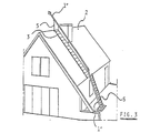
- a flag-pole as a complete structure denominated 1, is shown located near a house, having an inclined roof surface 2, on which surface 2 a ladder 3 is permanently attached in a previously known way.
- the flag-pole 1 With reference to the outer edge portion of the roof surface 2, the flag-pole 1 is located only a few metres from same, and with regard to the ladder 3, the flag-pole 1 is located adjacent to one side portion of same.
- the flag-pole 1 When the flag-pole 1 is in the position as shown in Fig. 1, it may be used as a conventional flag-pole 1, and there is no esthetically disturbing elements extending from same.
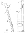
- a cranking handle 4 (figure 2) is inserted into the lower portion of the flagpole 1, said lower portion being denominated 1'.
- the lower portion 1' which is a tubular member, surrounds a winch, a gear reduction transmission or similar means, which can be operated by means of the cranking handle 4.
- Said winch or gear transmission is arranged connected to the base of the flag-pole 1 and also to the upper point of the lower portion 1' of the flag-pole.
- An upper portion of the flag-pole 1, denominated 1" is pivotably attached to the upper point of the lower portion 1', and when the cranking handle 4 is turned, the lower portion of the flag- pole 1' is slightly tilted in direction towards the outer edge portion of the roof surface 2, and at the same time the upper portion 1 " is also tilted relative to the lower portion and to an angle in relation to the ground mainly corresponding to the angle of the roof surface 2 in relation to the ground.
- a support member 5 extends vertically from the ridge of the roof, and the upper portion 1" is lowered until it rests on the support member 5.
- a locking mechanism is arranged, which can be manually released, and thus facilitate the movement in direction from the surrounding groove or channel. Furthermore, abutment means are also arranged, which hold the steps of the ladder 6 in a position extending mainly perpendicularly from the length axis of the lower portion 1' of the flag-pole, when the ladder 6 is swung out.
- the flag-pole 1 extends as shown in Fig. 3, i.e. the lower portion 1' is slightly tilted towards the outer edge portion of the roof surface 2, and the upper portion 1" extends at an angle mainly corresponding to the inclination of the roof surface 2 in a mainly parallel relationship to same, but located at a distance from the roof surface 2.
- the ladder 6, formed by means of the lower portion 1' of the flag-pole and the steps with interconnecting longitudinal member, extends from the ground to the outer edge portion of the roof surface, thus forming an extension to the fixed ladder 3 attached against the roof surface.
- the ladder 6 swung out from the flag-pole 1 is mounted in a conventional manner, and when reaching the outer edge portion of the roof surface, the upper portion 1" of the flag-pole is used as a hand rail, when moving from the first ladder 6 to the ladder 3 attached against the roof surface.
- the upper portion 1" of the flag- pole, used as a hand rail makes it extremely simple to move from the first ladder 6 to the second ladder 3, and it is also possible to climb the second ladder 3 in an upright position.
- the ladder 6 formed on the lower portion 1' of the flag-pole is swung back into the groove or the channel in said portion 1', and previously mentioned locking mechanism secures same surrounded by the lower portion 1' of the flag-pole.
- the longitudinally extending member, which joins each step will now be located outside the steps and closes the groove or the channel, with the outside surface preferably arranged to join the outer peripheral surface of the lower portion 1' of the flag-pole.
- Figs. 4 and 5 shown in an enlarged scale how the flag-pole 1 as disclosed above is arranged, but these figures only intend to indicate how the winch or gear reduction transmission, operated by the cranking handle 4, may be interconnected to achieve the described tilting action.
- the embodiment shown and described may be modified in a number of ways, whilst maintaining many of the advantages achieved with a flag-pole 1 as described and shown.
- the lower portion 1' of the flag-pole may be rigidly attached to the ground plane, i.e. with only the upper portion 1" tiltable when the cranking handle 4 is inserted and operated.
- Such a modification simplifies the design of the flag-pole 1, but as a result, the lower portion 1' must be located more adjacently to the outer edge portion of the roof surface 2, to facilitate movement from the first ladder 6 to the ladder or steps 3 attached against the roof surface 2.
- the flag-pole 1 may also be arranged as one unit only, i.e. without an upper 1" and a lower portion 1' pivotably joined to each other.
- the entire length of the flag-pole 1 is tilted towards the outer edge portion of the roof surface 2, the lower part of the flag-pole 1 being arranged with steps forming a ladder 6, thus facilitating climbing to the roof surface 2.
- the remaining length of the flag-pole 1 can still be used as a support means when climbing onto or leaving the roof surface 2, but this modification would obviously remove one important feature, i.e. there would be no hand rail which assists movement along the ladder 3 attached against the roof surface 2.
- each step in the ladder 6, formed in conjunction with the lower portion 1' may also be excluded, in which case either each step may be individually swung in direction from and to the flag-pole 1, or the steps may be joined by an interconnecting member surrounded by the flag-pole 1 adjacent to the end portions pivotably attached to the flag-pole 1, thus facilitating simultaneous movement of all steps.
- the means for climbing the lower portion 1' of the flag-pole may be further altered, particularly when the flag-pole 1 is extremely long, i.e. located nearby a multi-storey building, and intended to facilitate access to the roof of same.
- the means forming a ladder 6 in the previously discussed embodiments could in this case be arranged as cogs or teeth, located in a groove or a channel in the flag-pole 1, arranged to interconnect with a cog-wheel or similar driven by a motor, forming part of a flatform which can be elevated along the flag-pole 1.
- a platform would, when not in use, be located at the ground plane, and when the motor is operated, e.g. an electric motor, the platform would move up along the flag-pole 1.
- Said flag-pole may, as previously discussed, either be arranged as two separate parts 1', 1", arranged to take up tilted positions inclined towards the roof, or with only the upper portion 1" tilted, or with the entire flag-pole 1 as a unit tilted towards the roof of an adjacent house or building.
- the platform may also be arranged with a surrounding hand rail, which when not in use is folded down, located adjacently to the surface of the platform.
- Possible modifications also include the use of independent means for climbing to the roof, which means are attachable against the lower portion 1' of the flag-pole.
- Such means may comprise of individual steps, attachable to the flag-pole 1, e.g. by insertion into through holes extending transversely and spaced apart in the length direction of the flag-pole 1, or by means of a ladder or similar structure, attachable against attachment means located by the lower portion 1' of the flag-pole 1.
Landscapes
- Engineering & Computer Science (AREA)
- Architecture (AREA)
- Mechanical Engineering (AREA)
- Civil Engineering (AREA)
- Structural Engineering (AREA)
- Ladders (AREA)
- Transition And Organic Metals Composition Catalysts For Addition Polymerization (AREA)
- Inorganic Insulating Materials (AREA)
- Valve Device For Special Equipments (AREA)
Claims (10)
Priority Applications (1)
| Application Number | Priority Date | Filing Date | Title |
|---|---|---|---|
| AT81901886T ATE7940T1 (de) | 1980-06-23 | 1981-06-18 | Flaggenmast. |
Applications Claiming Priority (4)
| Application Number | Priority Date | Filing Date | Title |
|---|---|---|---|
| SE8004633 | 1980-06-23 | ||
| SE8004633 | 1980-06-23 | ||
| SE8006099 | 1980-09-01 | ||
| SE8006099A SE8006099L (sv) | 1980-06-23 | 1980-09-01 | Flaggstang |
Publications (2)
| Publication Number | Publication Date |
|---|---|
| EP0062036A1 EP0062036A1 (fr) | 1982-10-13 |
| EP0062036B1 true EP0062036B1 (fr) | 1984-06-13 |
Family
ID=26657609
Family Applications (1)
| Application Number | Title | Priority Date | Filing Date |
|---|---|---|---|
| EP81901886A Expired EP0062036B1 (fr) | 1980-06-23 | 1981-06-18 | Hampe de drapeau |
Country Status (8)
| Country | Link |
|---|---|
| US (1) | US4515241A (fr) |
| EP (1) | EP0062036B1 (fr) |
| CH (1) | CH647293A5 (fr) |
| DE (1) | DE3164137D1 (fr) |
| DK (1) | DK70682A (fr) |
| FI (1) | FI67909C (fr) |
| NO (1) | NO152104C (fr) |
| WO (1) | WO1982000042A1 (fr) |
Cited By (1)
| Publication number | Priority date | Publication date | Assignee | Title |
|---|---|---|---|---|
| CN106703497A (zh) * | 2016-12-27 | 2017-05-24 | 国网山东省电力公司蓬莱市供电公司 | 一种电力铁塔防攀爬装置 |
Families Citing this family (7)
| Publication number | Priority date | Publication date | Assignee | Title |
|---|---|---|---|---|
| US7059451B2 (en) * | 2002-09-26 | 2006-06-13 | Richey William H | Load lowering system |
| WO2004113649A2 (fr) * | 2003-06-20 | 2004-12-29 | Colonial Discount Flag & Flagpole Co. | Dispositif de drisse pour mat de drapeau |
| FR2865998B1 (fr) * | 2004-02-10 | 2006-04-28 | Airbus France | Echelle de communication entre un niveau superieur et un niveau inferieur d 'un aeronef, et aeronef muni d'une telle echelle |
| US7383922B1 (en) | 2004-04-01 | 2008-06-10 | Richey William H | Load stopping system |
| CN103061569A (zh) * | 2012-12-31 | 2013-04-24 | 无锡职业技术学院 | 一种智能旗帜升降系统及其控制方法 |
| CN104100198B (zh) * | 2014-07-31 | 2016-07-06 | 上海都市绿色工程有限公司 | 温室钢梯与外遮阳骨架连接装置 |
| RU172653U1 (ru) * | 2015-12-28 | 2017-07-18 | Закрытое акционерное общество "Центр специальных инженерных сооружений научно-исследовательского и конструкторского института радиоэлектронной техники" (ЗАО "ЦеСИС НИКИРЭТ") | Опора складывающаяся |
Family Cites Families (24)
| Publication number | Priority date | Publication date | Assignee | Title |
|---|---|---|---|---|
| US438036A (en) * | 1890-10-07 | Edmond verstraete | ||
| SE70270C1 (fr) * | 1930-01-01 | |||
| DE275304C (fr) * | ||||
| DE470163C (de) * | 1929-01-07 | Magirus Werk Berlin G M B H | Ausziehbarer Mast mit einer gleichzeitig ausziehbaren Leiter | |
| US426267A (en) * | 1890-04-22 | Fruit-picking stand | ||
| US627893A (en) * | 1898-09-12 | 1899-06-27 | Edward P Becker | Fireman's ladder. |
| US829336A (en) * | 1906-01-25 | 1906-08-21 | Jesse H Haycock | Pole-step. |
| US907483A (en) * | 1908-03-07 | 1908-12-22 | Ette Invest Company | Pole-step. |
| US946665A (en) * | 1908-03-23 | 1910-01-18 | Ette Invest Company | Cast-metal pole. |
| GB191004018A (en) * | 1910-02-18 | 1910-07-14 | John Weir | Improvements in and relating to Stepped Ladders for Electric Lamp Posts, Signal Posts, Fire-escapes and the like. |
| US1103719A (en) * | 1914-02-12 | 1914-07-14 | Perry O Wheeler | Step. |
| US1191405A (en) * | 1915-03-26 | 1916-07-18 | Peter E Daubenspeck | Combination fire-escape and costumer. |
| US1439030A (en) * | 1920-06-28 | 1922-12-19 | Firm Luftschiffbau Zeppelin Gm | Aircraft ladder |
| US2271609A (en) * | 1941-09-25 | 1942-02-03 | Charles R Hall | Flagstaff |
| US2358343A (en) * | 1942-12-30 | 1944-09-19 | Maxey Robert E Lee | Pole |
| US2875865A (en) * | 1953-03-31 | 1959-03-03 | Rohn Ivan Dwight | Collapsible antenna tower |
| US2822066A (en) * | 1953-06-26 | 1958-02-04 | Gewaine H Hanson | Outdoor standard |
| DE1258051B (de) * | 1962-11-12 | 1968-01-04 | Lang Heinz | Einholmleiter |
| FR1421544A (fr) * | 1964-11-03 | 1965-12-17 | Echelle extensible, à un seul montant, et à échelons repliables | |
| US3473628A (en) * | 1968-08-19 | 1969-10-21 | L E Lindsey | Retractable footstep for utility poles and the like |
| FR2252018A7 (en) * | 1973-10-23 | 1975-06-13 | Poivre Robert | Scaffolding ladder with movable rungs - ends of rungs have rings with locking devices surrounding ladder posts |
| US3995714A (en) * | 1975-11-17 | 1976-12-07 | Brookes Malcolm J | Multi-section ladder for scaling poles |
| FR2409371A1 (fr) * | 1977-11-21 | 1979-06-15 | Quintana Robert | Echelons retractables |
| US4258828A (en) * | 1979-08-22 | 1981-03-31 | Evans Ronald K | Folding mast ladder |
-
1981
- 1981-06-18 CH CH1171/82A patent/CH647293A5/fr not_active IP Right Cessation
- 1981-06-18 WO PCT/SE1981/000184 patent/WO1982000042A1/fr not_active Ceased
- 1981-06-18 DE DE8181901886T patent/DE3164137D1/de not_active Expired
- 1981-06-18 EP EP81901886A patent/EP0062036B1/fr not_active Expired
-
1982
- 1982-02-18 DK DK70682A patent/DK70682A/da not_active Application Discontinuation
- 1982-02-23 NO NO820563A patent/NO152104C/no unknown
- 1982-07-23 FI FI822604A patent/FI67909C/fi not_active IP Right Cessation
-
1984
- 1984-03-21 US US06/591,897 patent/US4515241A/en not_active Expired - Fee Related
Cited By (1)
| Publication number | Priority date | Publication date | Assignee | Title |
|---|---|---|---|---|
| CN106703497A (zh) * | 2016-12-27 | 2017-05-24 | 国网山东省电力公司蓬莱市供电公司 | 一种电力铁塔防攀爬装置 |
Also Published As
| Publication number | Publication date |
|---|---|
| DK70682A (da) | 1982-02-18 |
| NO152104B (no) | 1985-04-22 |
| WO1982000042A1 (fr) | 1982-01-07 |
| US4515241A (en) | 1985-05-07 |
| NO152104C (no) | 1985-07-31 |
| FI822604L (fi) | 1982-12-24 |
| EP0062036A1 (fr) | 1982-10-13 |
| DE3164137D1 (en) | 1984-07-19 |
| NO820563L (no) | 1982-02-23 |
| CH647293A5 (fr) | 1985-01-15 |
| FI67909C (fi) | 1985-06-10 |
| FI822604A0 (fi) | 1982-07-23 |
| FI67909B (fi) | 1985-02-28 |
Similar Documents
| Publication | Publication Date | Title |
|---|---|---|
| US9022172B2 (en) | Ladder accessory | |
| US8468632B1 (en) | Tactical access ramp | |
| EP0062036B1 (fr) | Hampe de drapeau | |
| US20210140182A1 (en) | Scaffold Having Lift Apparatus | |
| US4102433A (en) | Ladder | |
| EP1556563B1 (fr) | Unite de construction | |
| US5311965A (en) | Auto life-saving ladder | |
| EP3658238A1 (fr) | Système d'évacuation d'urgence modulaire et orientable | |
| CA1275279C (fr) | Echelle pliante d'evacuation en cas d'incendie, a l'epreuve du deploiement ou de l'emploi par des voleurs, et montee a fixations de deploiement distinctes, ainsi que garnie de ceintures de securite a supports verrouillables | |
| EP1666100B1 (fr) | Cage de sauvetage | |
| US4770272A (en) | Safety attachment for ladder | |
| EP2031150A2 (fr) | Système d'escalier d'échafaudage | |
| CA1332728C (fr) | Escaliers de secours installes a l'exterieur des batiments | |
| US6029773A (en) | Tubular emergency exit for buildings | |
| CA1187348A (fr) | Mat articule porte-drapeau | |
| US4901818A (en) | Fire fighting roof ladder accessory | |
| CA2305199A1 (fr) | Echelle avec dispositif d'appui a plate-forme auxiliaire laterale | |
| US6260662B1 (en) | Rectractable extension for the guiding rail of a climbing guard | |
| CN219764330U (zh) | 一种具有逃生功能的护栏 | |
| NZ243635A (en) | Emergency escape structure with stabilised conveyor ladder for use beside tall buildings | |
| ES2299642T3 (es) | Dispositivo de barrera de seguridad. | |
| DE19544819C1 (de) | Bedarfsweise herrichtbarer Notausstieg für Dachgeschosse oder Spitzböden | |
| JP2000144643A (ja) | 高架道路の非常脱出設備 | |
| US4261434A (en) | Fire escape device | |
| WO1984004560A1 (fr) | Echelles de secours pour batiments hauts |
Legal Events
| Date | Code | Title | Description |
|---|---|---|---|
| PUAI | Public reference made under article 153(3) epc to a published international application that has entered the european phase |
Free format text: ORIGINAL CODE: 0009012 |
|
| 17P | Request for examination filed |
Effective date: 19820712 |
|
| AK | Designated contracting states |
Designated state(s): AT CH DE FR GB NL SE |
|
| GRAA | (expected) grant |
Free format text: ORIGINAL CODE: 0009210 |
|
| AK | Designated contracting states |
Designated state(s): AT CH DE FR GB LI NL SE |
|
| REF | Corresponds to: |
Ref document number: 7940 Country of ref document: AT Date of ref document: 19840615 Kind code of ref document: T |
|
| REF | Corresponds to: |
Ref document number: 3164137 Country of ref document: DE Date of ref document: 19840719 |
|
| ET | Fr: translation filed | ||
| PLBE | No opposition filed within time limit |
Free format text: ORIGINAL CODE: 0009261 |
|
| STAA | Information on the status of an ep patent application or granted ep patent |
Free format text: STATUS: NO OPPOSITION FILED WITHIN TIME LIMIT |
|
| 26N | No opposition filed | ||
| PGFP | Annual fee paid to national office [announced via postgrant information from national office to epo] |
Ref country code: NL Payment date: 19870630 Year of fee payment: 7 |
|
| PGFP | Annual fee paid to national office [announced via postgrant information from national office to epo] |
Ref country code: AT Payment date: 19891222 Year of fee payment: 9 Ref country code: CH Payment date: 19891222 Year of fee payment: 9 Ref country code: FR Payment date: 19891222 Year of fee payment: 9 |
|
| PGFP | Annual fee paid to national office [announced via postgrant information from national office to epo] |
Ref country code: DE Payment date: 19891229 Year of fee payment: 9 |
|
| PGFP | Annual fee paid to national office [announced via postgrant information from national office to epo] |
Ref country code: GB Payment date: 19891231 Year of fee payment: 9 |
|
| PG25 | Lapsed in a contracting state [announced via postgrant information from national office to epo] |
Ref country code: NL Effective date: 19900101 |
|
| NLV4 | Nl: lapsed or anulled due to non-payment of the annual fee | ||
| PG25 | Lapsed in a contracting state [announced via postgrant information from national office to epo] |
Ref country code: AT Effective date: 19900618 Ref country code: GB Effective date: 19900618 |
|
| PG25 | Lapsed in a contracting state [announced via postgrant information from national office to epo] |
Ref country code: LI Effective date: 19900630 Ref country code: CH Effective date: 19900630 |
|
| GBPC | Gb: european patent ceased through non-payment of renewal fee | ||
| PG25 | Lapsed in a contracting state [announced via postgrant information from national office to epo] |
Ref country code: FR Effective date: 19910228 |
|
| REG | Reference to a national code |
Ref country code: CH Ref legal event code: PL |
|
| PG25 | Lapsed in a contracting state [announced via postgrant information from national office to epo] |
Ref country code: DE Effective date: 19910301 |
|
| REG | Reference to a national code |
Ref country code: FR Ref legal event code: ST |
|
| PGFP | Annual fee paid to national office [announced via postgrant information from national office to epo] |
Ref country code: SE Payment date: 19910627 Year of fee payment: 11 |
|
| PG25 | Lapsed in a contracting state [announced via postgrant information from national office to epo] |
Ref country code: SE Effective date: 19920619 |
|
| EUG | Se: european patent has lapsed |
Ref document number: 81901886.2 Effective date: 19930109 |