EP0062045B1 - Verfahren und vorrichtung zum ölen eines stahlkabels - Google Patents
Verfahren und vorrichtung zum ölen eines stahlkabels Download PDFInfo
- Publication number
- EP0062045B1 EP0062045B1 EP81902687A EP81902687A EP0062045B1 EP 0062045 B1 EP0062045 B1 EP 0062045B1 EP 81902687 A EP81902687 A EP 81902687A EP 81902687 A EP81902687 A EP 81902687A EP 0062045 B1 EP0062045 B1 EP 0062045B1
- Authority
- EP
- European Patent Office
- Prior art keywords
- chamber
- pressure
- lubricant
- steel cable
- pump
- Prior art date
- Legal status (The legal status is an assumption and is not a legal conclusion. Google has not performed a legal analysis and makes no representation as to the accuracy of the status listed.)
- Expired
Links
- 229910000831 Steel Inorganic materials 0.000 title claims abstract description 23
- 239000010959 steel Substances 0.000 title claims abstract description 23
- 230000001050 lubricating effect Effects 0.000 title claims abstract description 15
- 238000000034 method Methods 0.000 title claims abstract description 11
- 239000000314 lubricant Substances 0.000 claims abstract description 20
- 239000003921 oil Substances 0.000 claims abstract description 16
- 239000010687 lubricating oil Substances 0.000 claims abstract description 7
- 229920001971 elastomer Polymers 0.000 abstract description 4
- 239000004519 grease Substances 0.000 description 9
- 238000004140 cleaning Methods 0.000 description 2
- 238000005461 lubrication Methods 0.000 description 2
- 238000010420 art technique Methods 0.000 description 1
- 239000011248 coating agent Substances 0.000 description 1
- 238000000576 coating method Methods 0.000 description 1
- 238000010276 construction Methods 0.000 description 1
- 239000012530 fluid Substances 0.000 description 1
- 238000009434 installation Methods 0.000 description 1
- 230000001681 protective effect Effects 0.000 description 1
- 230000001105 regulatory effect Effects 0.000 description 1
- 229920006395 saturated elastomer Polymers 0.000 description 1
- 239000013535 sea water Substances 0.000 description 1
- 239000002689 soil Substances 0.000 description 1
Images

Classifications
-
- B—PERFORMING OPERATIONS; TRANSPORTING
- B66—HOISTING; LIFTING; HAULING
- B66D—CAPSTANS; WINCHES; TACKLES, e.g. PULLEY BLOCKS; HOISTS
- B66D1/00—Rope, cable, or chain winding mechanisms; Capstans
- B66D1/28—Other constructional details
-
- D—TEXTILES; PAPER
- D07—ROPES; CABLES OTHER THAN ELECTRIC
- D07B—ROPES OR CABLES IN GENERAL
- D07B7/00—Details of, or auxiliary devices incorporated in, rope- or cable-making machines; Auxiliary apparatus associated with such machines
- D07B7/02—Machine details; Auxiliary devices
- D07B7/12—Machine details; Auxiliary devices for softening, lubricating or impregnating ropes, cables, or component strands thereof
-
- F—MECHANICAL ENGINEERING; LIGHTING; HEATING; WEAPONS; BLASTING
- F16—ENGINEERING ELEMENTS AND UNITS; GENERAL MEASURES FOR PRODUCING AND MAINTAINING EFFECTIVE FUNCTIONING OF MACHINES OR INSTALLATIONS; THERMAL INSULATION IN GENERAL
- F16N—LUBRICATING
- F16N2210/00—Applications
- F16N2210/34—Cables and wires
Definitions
- the present invention relates to a method for lubricating steel cable, wherein the steel cable is drawn through a sleeve-shaped gasket into a chamber containing lubricant under pressure and withdrawn from the chamber through a second sleeve-shaped gasket.
- the invention also relates to an apparatus for implementing the method.
- German Patent No. 25 49 487 discloses a lubricating device which in one embodiment has a sleeve-shaped chamber having an opening with a sleeve-shaped gasket through which the cable is inserted at one end of the chamber and an outlet opening for the cable, also with a sleeve-shaped gasket, at the other end thereof, lubricant under pressure being supplied to the chamber through a hose.
- the construction of this known apparatus is based on the prior art techniques of lubricating cable, i.e., coating the outside circumference of the cable with lubricant applied with a brush or the like.
- lubricant preferably grease
- the object of the present invention is to eliminate the above drawbacks, providing a method and an apparatus whereby one can obtain effective lubrication of steel cables, without spillage and at a high rate of speed.
- a liquid lubricant is used, preferably a lubricating oil
- the lubricant is supplied to the chamber by means of a pump having a high pressure and low capacity characteristic with a delivery pressure of minimum 20 bar and preferably above 40 bar, and that the rate at which the steel cable is drawn through the lubricant is adapted such that the hollow spaces in the cable absorb the oil to such a degree that oil leakage through the gaskets is avoided.
- the lubricant will immediately be forced into all the hollow spaces in a steel cable.
- leakage will be reduced to a minimum. This balance between the rate of passage for the cable through the chamber and the pressure and capacity of the pump is not critical, either.
- a steel cable as everyone knows, consists of a mass of intertwined steel wires which collectively have a very large surface. The oil will thus not spurt out between the moving cable and the surrounding gasket, as occurs with grease, but will seep into the cable and disperse itself on the surface of the large number of steel wires. Even if the cable is saturated with oil in all the hollow spaces, the dripping from the cable as it passes out of the chamber will still be very small.
- An apparatus for carrying out the method comprises a chamber intended to hold a lubricant under pressure, having an inlet and an outlet, each with tight-fitting sleeve-shaped gaskets, for the steel cable, a supply hose for the lubricant which is connected to the chamber, and a pressure pump for providing pressure in the lubricant, and the characteristic feature of the apparatus is that the pump is a pump which can deliver a pressure of at least 20 bar, preferably above 40 bar, and has a small delivery capacity.
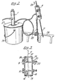
- the apparatus consists of a pump 1 with a suction pipe 2, connected to a hose 3 on the pressure side which leads to a lubricating chamber 4.
- the pump 1 in the illustrated embodiment example, is a pressurized air-driven pump which is supplied with pressurized air at, for instance, 12 bar through a conduit 5 over a valve 6.
- the pump can deliver 40 times the supplied pressure, but has a small capacity.
- the chamber 4 consists of two halves 7,8 which are hinged together by means of hinges 9, 10 ( Figure 3) such that a cable 11 can be inserted into the chamber when the halves 7, 8 are in an open position.
- an opening 12, 13 for the cable 11 which is to be lubricated.
- tight-fitting rubber gaskets 14, 15 made of an oil-resistant rubber quality.
- the aperture 16 in the gaskets is dimensioned somewhat smaller than the diameter of the cable 11 which is to pass therethrough.
- the sleeves 14,15 have a radial slit extending from the outer margin all the way in to the aperture 16. This slit is indicated in Figure 3 in that the right-hand portion of each of the sleeves 14 and 15 is not shaded in the drawing.
- the locking means consist of two lugs on each of the sleeve halves at the division between the sleeves. Attached to the lugs 20 on the sleeve half 8 is the cross-piece of a T-shaped bolt 21, which is threaded on the opposite, stem end thereof. The bolt can be tightened against the lugs 23 on the other sleeve half 7 by means of a nut 22. Between the sleeve halves, a gasket 24 is provided.
- a chain 25 is attached to the lubricating chamber 4; during use, the chain can be secured to a railing 26 or the like.
- the chamber 4 is threaded onto the cable 11 and the chamber 4 is anchored to a railing or some other fixture by means of the chain 25.
- the pump 1 is passed down through a hole in a specially made lid 27 on a bucket of oil 28.
- the lid does not have to be particularly tight-fitting, as the oil is merely sucked up from the bucket.
- the pump is started and provides the chamber 4 with a small amount of oil at high pressure, and the cable 11 is drawn in the direction of the arrow 29.
- the rate of advance of the cable is regulated according to the pressure and capacity of the pump so that one avoids leakage.
Landscapes
- Engineering & Computer Science (AREA)
- Mechanical Engineering (AREA)
- Coating Apparatus (AREA)
- Sealing Devices (AREA)
- Ropes Or Cables (AREA)
- Electric Cable Installation (AREA)
- Lubricants (AREA)
- Coating By Spraying Or Casting (AREA)
Claims (2)
Priority Applications (1)
| Application Number | Priority Date | Filing Date | Title |
|---|---|---|---|
| AT81902687T ATE12412T1 (de) | 1980-10-06 | 1981-10-06 | Verfahren und vorrichtung zum oelen eines stahlkabels. |
Applications Claiming Priority (2)
| Application Number | Priority Date | Filing Date | Title |
|---|---|---|---|
| NO802958 | 1980-10-06 | ||
| NO802958A NO164671C (no) | 1980-10-06 | 1980-10-06 | Fremgangsmåte til smöring av ståltau. |
Publications (2)
| Publication Number | Publication Date |
|---|---|
| EP0062045A1 EP0062045A1 (de) | 1982-10-13 |
| EP0062045B1 true EP0062045B1 (de) | 1985-03-27 |
Family
ID=19885690
Family Applications (1)
| Application Number | Title | Priority Date | Filing Date |
|---|---|---|---|
| EP81902687A Expired EP0062045B1 (de) | 1980-10-06 | 1981-10-06 | Verfahren und vorrichtung zum ölen eines stahlkabels |
Country Status (9)
| Country | Link |
|---|---|
| US (1) | US4422529A (de) |
| EP (1) | EP0062045B1 (de) |
| JP (1) | JPS57501635A (de) |
| CA (1) | CA1148876A (de) |
| GB (1) | GB2084627B (de) |
| HK (1) | HK78585A (de) |
| NO (1) | NO164671C (de) |
| SG (1) | SG57585G (de) |
| WO (1) | WO1982001201A1 (de) |
Cited By (1)
| Publication number | Priority date | Publication date | Assignee | Title |
|---|---|---|---|---|
| KR20220117071A (ko) * | 2021-02-16 | 2022-08-23 | 주진희 | 와이어로프 윤활장치 |
Families Citing this family (20)
| Publication number | Priority date | Publication date | Assignee | Title |
|---|---|---|---|---|
| AU566378B2 (en) * | 1984-04-24 | 1987-10-15 | Vladimir Gavrilovich Churkin | Method and hydraulic cylinder for sealing lengthy borous bodies |
| US4542787A (en) * | 1984-05-29 | 1985-09-24 | Parker Richard W | Wireline oil pan |
| AU7588287A (en) * | 1986-06-10 | 1988-01-11 | Robert L. Schneider | Service lubricating of metal haulage cables |
| NO160797C (no) * | 1986-11-21 | 1989-05-31 | Hans Knut Waage | Anordning ved smoereapparat for vaier. |
| GB9711155D0 (en) * | 1997-05-31 | 1997-07-23 | Jenkins Anthony S | Linkage arrangement |
| JP2002120434A (ja) * | 2000-07-31 | 2002-04-23 | Hewlett Packard Co <Hp> | 印刷された媒体用の保護アンダーコーティング |
| US6725973B2 (en) | 2000-11-16 | 2004-04-27 | Wld, Llc | Automatic wire lubricating device |
| US20050274576A1 (en) * | 2000-11-16 | 2005-12-15 | Coder Timothy L | Strand lubrication |
| US20040035642A1 (en) * | 2000-11-16 | 2004-02-26 | Coder Timothy L. | Strand lubrication |
| US7143866B2 (en) * | 2000-11-16 | 2006-12-05 | Wld, Llc | Strand lubrication |
| US6783593B2 (en) | 2001-04-03 | 2004-08-31 | Dynacon, Inc. | Rotary cable treatment method and apparatus |
| US7164013B2 (en) * | 2003-08-15 | 2007-01-16 | Korea Kumho Petrochemical Co., Ltd. | Hyperactive light signal related molecule of HFR1-ΔN105 and transgenic plant thereof |
| CN104444887A (zh) * | 2014-11-11 | 2015-03-25 | 兖州煤业股份有限公司 | 绞车及其润滑装置 |
| JP6423756B2 (ja) * | 2015-05-18 | 2018-11-14 | 株式会社日立製作所 | 潤滑剤塗布装置、並びに、これを用いたエレベータ及びエレベータの保守方法 |
| DE102016122905A1 (de) | 2016-11-28 | 2018-05-30 | Wobben Properties Gmbh | Spannlitzenaufspreizvorrichtung, Spannlitzenschmiervorrichtung und -verfahren |
| US11148744B2 (en) * | 2018-10-23 | 2021-10-19 | Clark Edward McCall | Reusable cup for cable lubrication |
| CN113302428B (zh) * | 2019-01-14 | 2023-08-01 | 理想工业公司 | 用于润滑电缆或类似物的系统 |
| EP3702203B1 (de) * | 2019-02-27 | 2023-07-05 | Furrer + Frey AG | Fettmanschette |
| US11753237B2 (en) * | 2019-09-24 | 2023-09-12 | Dennis Rose | Oil tank sealing device with optional cable greaser and related methods |
| US12006013B2 (en) * | 2021-11-23 | 2024-06-11 | Jayce Raper | Lubricating tool for boat steering cable |
Family Cites Families (11)
| Publication number | Priority date | Publication date | Assignee | Title |
|---|---|---|---|---|
| US1049170A (en) * | 1910-12-27 | 1912-12-31 | Harry P Thomas | Device for applying a lubricant or filler to cables. |
| US1393860A (en) * | 1920-08-12 | 1921-10-18 | Weeks Edward Chester | Machine for coating or covering material |
| US2435120A (en) * | 1945-01-30 | 1948-01-27 | Harry E Baker | Cable greasing device |
| CH493280A (de) * | 1962-09-14 | 1970-07-15 | Asahi Chemical Ind | Vorrichtung zur Behandlung von Textilsträngen |
| SU583501A1 (ru) * | 1970-05-29 | 1977-12-05 | Московские Отделы Специального Конструкторско-Технологического Бюро По Изоляторам И Арматуре Треста "Электросетьизоляция" | Устройство дл смазки проводов и тросов |
| US3733216A (en) * | 1971-04-19 | 1973-05-15 | Western Electric Co | Method for impregnating stranded cable with waterproofing compound |
| IT996938B (it) * | 1973-11-12 | 1975-12-10 | Acerbi Virgilio | Dispositivo ingrassatore per cavi |
| AT337283B (de) * | 1974-01-25 | 1977-06-27 | Gen Cable Corp | Verfahren und anlage zum impragnieren der aus mehreren leitern oder adern fertig verseilten seele eines kabels, insbesondere fernsprechkabels |
| US4046225A (en) * | 1975-08-11 | 1977-09-06 | Bell Telephone Laboratories, Incorporated | Cable lubrication method |
| SU605778A1 (ru) * | 1976-06-04 | 1978-05-05 | Предприятие П/Я Р-6109 | Устройство дл смазки канатов |
| US4326605A (en) * | 1979-11-19 | 1982-04-27 | Conti Armand R | Lubricating collar for cable |
-
1980
- 1980-10-06 NO NO802958A patent/NO164671C/no unknown
-
1981
- 1981-03-27 US US06/248,297 patent/US4422529A/en not_active Expired - Lifetime
- 1981-04-02 GB GB8110356A patent/GB2084627B/en not_active Expired
- 1981-04-08 CA CA000375018A patent/CA1148876A/en not_active Expired
- 1981-10-06 WO PCT/NO1981/000038 patent/WO1982001201A1/en not_active Ceased
- 1981-10-06 EP EP81902687A patent/EP0062045B1/de not_active Expired
- 1981-10-06 JP JP56503186A patent/JPS57501635A/ja active Pending
-
1985
- 1985-07-27 SG SG575/85A patent/SG57585G/en unknown
- 1985-10-10 HK HK785/85A patent/HK78585A/xx not_active IP Right Cessation
Cited By (1)
| Publication number | Priority date | Publication date | Assignee | Title |
|---|---|---|---|---|
| KR20220117071A (ko) * | 2021-02-16 | 2022-08-23 | 주진희 | 와이어로프 윤활장치 |
Also Published As
| Publication number | Publication date |
|---|---|
| US4422529A (en) | 1983-12-27 |
| NO164671B (no) | 1990-07-23 |
| WO1982001201A1 (en) | 1982-04-15 |
| CA1148876A (en) | 1983-06-28 |
| GB2084627A (en) | 1982-04-15 |
| HK78585A (en) | 1985-10-18 |
| NO802958L (no) | 1981-09-16 |
| GB2084627B (en) | 1985-01-30 |
| SG57585G (en) | 1986-11-21 |
| JPS57501635A (de) | 1982-09-09 |
| NO164671C (no) | 1995-04-03 |
| EP0062045A1 (de) | 1982-10-13 |
Similar Documents
| Publication | Publication Date | Title |
|---|---|---|
| EP0062045B1 (de) | Verfahren und vorrichtung zum ölen eines stahlkabels | |
| CZ20014180A3 (cs) | Způsob uvolňování zadřených ventilů | |
| CA2168998C (en) | Drain valve assembly | |
| AU541616B2 (en) | Method and apparatus for lubricating steel cable | |
| US5049031A (en) | Quick removal appartaus and method for lantern rings and packing in pump assemblies | |
| DE3590526T1 (de) | Verfahren zum Aufbringen eines aus Zement-Sand-Mörtel bestehenden Überzugs auf die Innenfläche einer Rohrleitung und Einrichtung zur Durchführung desselben | |
| EP0095421A3 (de) | Abdichtungsaufbau des Toleranzraumtyps für flüssiges Schmiermittel | |
| JP3474536B2 (ja) | ワイヤロープ潤滑装置及び潤滑システム | |
| US20020139616A1 (en) | Rotary cable treatment method and apparatus | |
| US3851623A (en) | Method of and device for coating lengths of linear elements | |
| US3459156A (en) | Device for impregnating wire rope | |
| US5404965A (en) | Apparatus for lubricating pipe joints | |
| JPS6133476A (ja) | ワイヤロ−プ自動塗油装置 | |
| CN114017658B (zh) | 一种有支撑管键连接的全悬挂舵系润滑脂加注法及其效果评估方法 | |
| US4427718A (en) | Wedge encapsulation method | |
| DE29622322U1 (de) | Wellenabdichtung für Yachtantriebe, ölgeschmiert mit Radialwellendichtringen und Stopfbuchse | |
| US4692064A (en) | Method to drill and tap a hollow underwater member | |
| US4832529A (en) | Method for repairing air core cable | |
| CN222527380U (zh) | 一种用于海洋缆绳快速均匀上油装置 | |
| DE3636419C2 (de) | ||
| SU1010386A1 (ru) | Способ укладки трубопровода на дно водоема | |
| GB2141506A (en) | Branch pipe connection | |
| SU421570A1 (ru) | Устройство для очистки и смазки стальных тросов | |
| SU1068327A1 (ru) | Устройство дл установки протектора в судовой системе забортной воды | |
| JPH04281914A (ja) | アンカー工法における防錆油の注入方法 |
Legal Events
| Date | Code | Title | Description |
|---|---|---|---|
| PUAI | Public reference made under article 153(3) epc to a published international application that has entered the european phase |
Free format text: ORIGINAL CODE: 0009012 |
|
| 17P | Request for examination filed |
Effective date: 19820601 |
|
| AK | Designated contracting states |
Designated state(s): AT CH DE FR LU NL SE |
|
| GRAA | (expected) grant |
Free format text: ORIGINAL CODE: 0009210 |
|
| AK | Designated contracting states |
Designated state(s): AT CH DE FR LI LU NL SE |
|
| PG25 | Lapsed in a contracting state [announced via postgrant information from national office to epo] |
Ref country code: LI Effective date: 19850327 Ref country code: CH Effective date: 19850327 Ref country code: AT Effective date: 19850327 |
|
| REF | Corresponds to: |
Ref document number: 12412 Country of ref document: AT Date of ref document: 19850415 Kind code of ref document: T |
|
| REF | Corresponds to: |
Ref document number: 3169569 Country of ref document: DE Date of ref document: 19850502 |
|
| REG | Reference to a national code |
Ref country code: CH Ref legal event code: PL |
|
| ET | Fr: translation filed | ||
| PG25 | Lapsed in a contracting state [announced via postgrant information from national office to epo] |
Ref country code: LU Free format text: LAPSE BECAUSE OF NON-PAYMENT OF DUE FEES Effective date: 19851031 |
|
| PLBE | No opposition filed within time limit |
Free format text: ORIGINAL CODE: 0009261 |
|
| STAA | Information on the status of an ep patent application or granted ep patent |
Free format text: STATUS: NO OPPOSITION FILED WITHIN TIME LIMIT |
|
| 26N | No opposition filed | ||
| REG | Reference to a national code |
Ref country code: FR Ref legal event code: TP |
|
| NLS | Nl: assignments of ep-patents |
Owner name: TOR BIRGER KRAGEBOEN TE TVEIT, NOORWEGEN. |
|
| EAL | Se: european patent in force in sweden |
Ref document number: 81902687.3 |
|
| PGFP | Annual fee paid to national office [announced via postgrant information from national office to epo] |
Ref country code: FR Payment date: 20000929 Year of fee payment: 20 |
|
| PGFP | Annual fee paid to national office [announced via postgrant information from national office to epo] |
Ref country code: DE Payment date: 20001012 Year of fee payment: 20 |
|
| PGFP | Annual fee paid to national office [announced via postgrant information from national office to epo] |
Ref country code: NL Payment date: 20001020 Year of fee payment: 20 |
|
| PGFP | Annual fee paid to national office [announced via postgrant information from national office to epo] |
Ref country code: SE Payment date: 20001030 Year of fee payment: 20 |
|
| PG25 | Lapsed in a contracting state [announced via postgrant information from national office to epo] |
Ref country code: NL Free format text: LAPSE BECAUSE OF EXPIRATION OF PROTECTION Effective date: 20011006 |
|
| PG25 | Lapsed in a contracting state [announced via postgrant information from national office to epo] |
Ref country code: SE Free format text: THE PATENT HAS BEEN ANNULLED BY A DECISION OF A NATIONAL AUTHORITY Effective date: 20011030 |
|
| EUG | Se: european patent has lapsed |
Ref document number: 81902687.3 |
|
| NLV7 | Nl: ceased due to reaching the maximum lifetime of a patent |
Effective date: 20011006 |