EP0062089A1 - Kugelkipplager für Zwei- oder Dreiseitenkipper - Google Patents
Kugelkipplager für Zwei- oder Dreiseitenkipper Download PDFInfo
- Publication number
- EP0062089A1 EP0062089A1 EP81102951A EP81102951A EP0062089A1 EP 0062089 A1 EP0062089 A1 EP 0062089A1 EP 81102951 A EP81102951 A EP 81102951A EP 81102951 A EP81102951 A EP 81102951A EP 0062089 A1 EP0062089 A1 EP 0062089A1
- Authority
- EP
- European Patent Office
- Prior art keywords
- ball
- locking element
- axis
- shell
- pin
- Prior art date
- Legal status (The legal status is an assumption and is not a legal conclusion. Google has not performed a legal analysis and makes no representation as to the accuracy of the status listed.)
- Granted
Links
Images


Classifications
-
- B—PERFORMING OPERATIONS; TRANSPORTING
- B60—VEHICLES IN GENERAL
- B60P—VEHICLES ADAPTED FOR LOAD TRANSPORTATION OR TO TRANSPORT, TO CARRY, OR TO COMPRISE SPECIAL LOADS OR OBJECTS
- B60P1/00—Vehicles predominantly for transporting loads and modified to facilitate loading, consolidating the load, or unloading
- B60P1/04—Vehicles predominantly for transporting loads and modified to facilitate loading, consolidating the load, or unloading with a tipping movement of load-transporting element
- B60P1/16—Vehicles predominantly for transporting loads and modified to facilitate loading, consolidating the load, or unloading with a tipping movement of load-transporting element actuated by fluid-operated mechanisms
- B60P1/167—Vehicles predominantly for transporting loads and modified to facilitate loading, consolidating the load, or unloading with a tipping movement of load-transporting element actuated by fluid-operated mechanisms three side tipping movement
Definitions
- the invention relates to a ball tilt bearing for two- or three-way tippers, in which the ball has a pin and is mounted in a shell which is approximately semicircular in cross section and the ball has contact with a holding element.
- Ball tipping bearings for two- or three-way tippers are known per se; they are usually arranged in the area of the four corners of the tipper body.
- the ball pin In the known ball tilt bearings, the ball pin is arranged essentially horizontally.
- the ball pivot is in this case attached to the vehicle frame and the ball housing is fastened to the tilting bridge, the tilting bridge executing pivoting movements around the ball.
- the known ball tilt bearings are in need of improvement in several respects.
- ball and socket bearings were very often provided with an interchangeable plastic insert, the hard stress when driving resulted in the plastic inserts being subjected to rapid wear, so that noise pollution occurred.
- the mechanical stress on the ball bearing was considerable due to the horizontal arrangement of the ball pin, so that breaks occasionally occurred due to material wear.
- the invention is based on the task of developing a ball tilt bearing, in which plug pins with a safety chain or similar devices are omitted, which require no maintenance and have devices that rule out noise pollution.
- plug pins with a safety chain or similar devices are omitted, which require no maintenance and have devices that rule out noise pollution.
- the invention is characterized in that the ball pin assumes a vertical position during the horizontal position of the tipper body and the ball shell has at least two sides, preferably on three sides, in its upper edge approximately semicircular recesses which serve to guide the ball pin during the tilting process
- Shell on one side has an outwardly projecting holder, in the upper part of which at least one locking element is tiltably supported on an axis, the contact surface of which extends into the semicircular shell, and at least one locking element in the upper part has laterally protruding T-shaped spring suspensions which face the Axis of rotation of at least one locking element are arranged at a distance
- the springs are provided symmetrically to the locking element and the lower ends of the springs are mounted on pins in the lower part of the holder and are adjustable such that the locking element rests on the ball in the ready-to-use state.
- the holder consists of two spaced disks, the locking element being arranged between these disks in a tiltable manner.
- at least one locking element on the outside has a T-shaped projection extending to both sides, through which the locking can be released by means of at least one pivotable rod, through which the ball can be removed.
- the tilting axis of the locking element is arranged in such a way that the locking element has a greater weight on the outside by means of the T-shaped projection, so that the locking element can also act against the spring force Ball supports and this locks automatically.
- the technical progress of the invention is that the ball bearing can remain practically without maintenance. It is also advantageous that, in contrast to the known ball tilt bearings, chains, insert bolts or the like are not required.
- a particular advantage is that two springs working in parallel are provided which press the locking element against the ball. If one spring fails due to breakage, the second spring is sufficient to lock the ball sufficiently in position. Finally, the ball can also be locked automatically when both springs fail, namely due to the special design of the locking element.
- the overall design of the ball tilt bearing offers, without any difficulty, the possibility that the ball can carry out tilting movements in three directions, the ball pin being guided laterally.
- the ball is denoted by 1 and the ball stud by 2.
- the ball 1 is supported in a shell 3 which is semicircular in the lower part and has extensions at the top, which has semicircular recesses 4 in its upper edge, which form for lateral guidance of the ball pin during movements in three directions.
- the shell 3 has on one side an outwardly projecting holder 5, which consists of two spaced disks, in the upper part of which a locking element 6 is pivotably mounted on an axis 12.
- This locking element 6 has a contact surface 7 which extends into the shell 3.
- the locking element 6 has in the upper part laterally projecting T-shaped spring suspensions 8, which are arranged in front of the axis of rotation 12 at a distance 14.
- the springs 9 which press the locking element 6 against the ball 1 are arranged symmetrically to the locking element 6.
- the lower ends of the spring 9 are mounted on pins 10 in the lower part of the holder 5. They are set such that the locking element bears against the ball 1 with the required contact pressure.
- the locking element 6 has on the outside a T-shaped projection 11 which extends to both sides and is arranged in a horizontal position.
- the projection 11 has a removable rod 17 through which the lock on the ball can be released by pressing down, so that the ball can be removed.
- the tilt axis 12 of the locking element 6 is arranged such that the arrangement of the T-shaped projection 11 creates an excess weight on the outer side of the tilt axis 12, so that the locking element 6 is pressed against the ball even without spring action, so that an automatic locking the ball 1 is formed in the shell 3, which makes it impossible to lift the ball out.
- Fig. 6 shows a second embodiment in which the bracket 15 consists of a disc. Laterally and symmetrically, two clamping elements 16 are provided, which are mounted on a tilt axis 12. The clamping elements 16 protrude into the shell of the ball bearing and serve in this way for locking the ball 1. At the outer ends of the clamping elements 16 a rod-shaped projection 21 is arranged, which has at its ends openings 22 for inserting the rods 17 with which the locking of the ball 1 can be released.
- the arms 8 in turn serve for the arrangement of coil springs 9, which generate the contact pressure of the locking elements 16 for abutting the ball 1.
Landscapes
- Engineering & Computer Science (AREA)
- Transportation (AREA)
- Mechanical Engineering (AREA)
- Pivots And Pivotal Connections (AREA)
- Rolling Contact Bearings (AREA)
Abstract
Description
- Die Erfindung betrifft ein Kugelkipplager für Zwei- oder Dreiseitenkipper, bei dem die Kugel einen Zapfen aufweist und in einer im Querschnitt etwa halbkreisförmigen Schale gelagert ist und die Kugel Kontakt mit einem Halteelement aufweist.
- Kugelkipplager für Zwei- oder Dreiseitenkipper sind an sich bekannt; sie sind in der Regel im Bereich der vier Ecken des Kipperaufbaues angeordnet. Bei den bekannten Kugelkipplagern ist der Kugelzapfen im wesentlichen horizontal angeordnet. Der Kugelzapfen ist hierbei am Fahrzeugrahmen, und das Kugelgehäuse an der Kippbrücke befestigt, wobei die Kippbrücke Schwenkbewegungen um die Kugel ausführt.
- Die bekannten Kugelkipplager sind in mehrfacher Beziehung verbesserungsbedürftig. Obwohl Kugelkipplager sehr oft mit einer auswechselbaren Kunststoffeinlage versehen wurden, hat sich durch die harte Beanspruchung beim Fahren ergeben, daß die Kunststoffeinlagen einem schnellen Verschleiß unterworfen waren, so daß eine Lärmbelästigung auftrat. Auch war es bei den bekannten Kugelkipplagern erforderlich einen Steckbolzen mit Sicherungskette zu verwenden, wodurch das Hantieren mit diesen Lagern eine umständliche Bedienung erforderlich machte. Schließlich war auch die mechanische Beanspruchung der Kugelkipplager infolge der horizontalen Anordnung des Kugelzapfens erheblich, so daß gelegentlich Brüche durch Materialverschleiß entstanden.
- Die Erfindung geht von der Aufgabenstellung aus, ein Kugelkipplager zu entwickeln, bei denen Steckbolzen mit Sicherungskette oder ähnliche Einrichtungen entfallen, das keinerlei Wartung bedarf und Einrichtungen aufweist, die eine Lärmbelästigung ausschließen. Hierbei wurde von der Erkenntnis ausgegangen, daß es grundsätzlich zweckmäßiger ist, wenn der Kugelzapfen in der Ruhestellung lotrecht steht.
- Die Erfindung ist dadurch gekennzeichnet, daß der Kugelzapfen während der Horizontallage des Kipperaufbaus eine lotrechte Stellung einnimmt und die Kugelschale an mindestens zwei Seiten, vorzugsweise an drei Seiten, in ihrem oberen Rand etwa halbkreisförmige Aussparungen aufweist, die zur Führung des Kugelzapfens beim Kippvorgang dienen, die Schale auf einer Seite eine nach außen vorspringende Halterung aufweist, in deren oberem Teil mindestens ein Sperrelement an einer Achse kippbar gelagert ist, deren Anlagefläche in die halbkreisförmige Schale hineinreicht, mindestens ein Sperrelement im oberen Teil seitlich herausstehende T-förmige Federaufhängungen aufweist, die vor der Drehachse mindestens eines Sperrelementes im Abstand angeordnet sind, die Federn symmetrisch zum Sperrelement vorgesehen sind und die unteren Enden der Federn im unteren Teil der Halterung an Zapfen gelagert und derart einstellbar sind, daß im betriebsfertigen Zustand das Sperrelement an der Kugel anliegt.
- Bei einer bevorzugten Ausführungsform der Erfindung besteht die Halterung aus zwei im Abstand angeordneten Scheiben, wobei zwischen diesen Scheiben das Sperrelement kippbar angeordnet ist. Bei einer weiteren Ausführungsform weist mindestens ein Sperrelement auf der Außenseite einen sich nach beiden Seiten erstreckenden T-förmigen Vorsprung auf, durch den mittels mindestens eines schwenkbaren Stabes die Sperrung lösbar ist, durch die Kugel herausnehmbar ist. Bei einer weiteren Ausführungsform ist die Kippachse beim Sperrelement derart angeordnet, daß das Sperrelement mittels des T-förmigen Vorsprungs außen ein größeres Gewicht aufweist, so daß das Sperrelement sich auch ohne Federeinwirkung gegen die Kugel abstützt und diese automatisch arretiert.
- Der technische Fortschritt der Erfindung besteht darin, daß das Kugelkipplager praktisch ohne Wartung bleiben kann. Vorteilhaft ist ferner, daß im Gegensatz zu den bekannten Kugelkipplagern Ketten, Einsteckbolzen od, dgl. nicht erforderlich sind. Ein besonderer Vorteil besteht darin, daß zwei parallel arbeitende Federn vorgesehen sind, die das Sperrelement gegen die Kugel pressen. Fällt eine Feder durch Bruch aus, genügt die zweite Feder um die Kugel ausreichend in ihrer Position zu arretieren. Schließlich kann eine Arretierung der Kugel auch dann automatisch erfolgen, wenn beide Federn ausfallen, nämlich durch die besondere Bauart des Sperrelementes. Schließlich ist technisch vorteilhaft, daß die Gesamtkonzeption des Kugelkipplagers ohne jegliche Schwierigkeit die Möglichkeit bietet, daß die Kugel mit den Zapfen Kippbewegungen nach drei Richtungen ausführen kann, wobei der Kugelzapfen seitlich geführt ist.
- In der Zeichnung sind zwei Ausführungsbeispiele der Erfindung dargestellt.
-
- Fig. 1 zeigt eine Seitenansicht des Kugelkipplagers mit eingebauter Kugel;
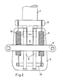
- Fig. 2 zeigt eine Vorderansicht ohne Kugel;
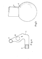
- Fig. 3 zeigt schematisch die Ausbildung der Kugel mit Zapfen;
- Fig. 4 zeigt eine schematische Seitenansicht des Sperrelementes;
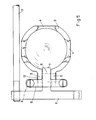
- Fig. 5 zeigt eine Aufsicht ohne Kugel;
- Fig. 6 zeigt die Aufsicht einer zweiten Ausführungsform.
- Bei der Ausführungsform nach Fig. 1 bis Fig. 5 ist die Kugel mit 1 und der Kugelzapfen mit 2 bezeichnet. Die Kugel 1 ist abgestützt in einer Schale 3 die im unteren Teil halbkreisförmig ausgebildet ist und nach oben Verlängerungen aufweist, die in ihrem oberen Rand halbkreisförmige Aussparungen 4 aufweist, die zur seitlichen Führung des Kugelzapfens bei Bewegungen nach drei Richtungen bilden. Die Schale 3 weist auf einer Seite eine nach außen vorspringende Halterung 5 auf, die aus zwei mit Abstand angeordneten Scheiben besteht, in deren oberem Teil ein Sperrelement 6 an einer Achse 12 kippbar gelagert ist. Dieses Sperrelement 6 weist eine Anlagefläche 7 auf, die in die Schale 3 hineinreicht. Das Sperrelement 6 weist im oberen Teil seitlich herausstehende T-förmige Federaufhängungen 8 auf, die vor der Drehachse 12 im Abstand 14 angeordnet sind. Wie die Darstellung in Fig. 2 erkennen läßt sind die Federn 9 die das Sperrelement 6 gegen die Kugel 1 pressen, symmetrisch zum Sperrelement 6 angeordnet. Die unteren Enden der Feder 9 sind im unteren Teil der Halterung 5 an Zapfen 10 gelagert. Sie sind derart eingestellt, daß das Sperrelement an der Kugel 1 mit dem erforderlichen Anpreßdruck anliegt.
- Das Sperrelement 6 weist auf der Außenseite einen sich nach beiden Seiten erstreckenden T-förmigen Vorsprung 11 auf, der in horizontaler Lage angeordnet ist. Der Vorsprung 11 weist einen herausnehmbaren Stab 17 auf, durch den durch Herunterdrücken die Sperrung an der Kugel lösbar ist, so daß die Kugel herausgenommen werden kann. Die Kippachse 12 des Sperrelementes 6 ist derart angeordnet, daß durch die Anordnung des T-förmigen Vorsprunges 11 ein Übergewicht auf der äußeren Seite der Kippachse 12 entsteht, so daß auch ohne Federwirkung das Sperrelement 6 gegen die Kugel gepreßt wird, so daß eine automatische Arretierung der Kugel 1 in der Schale 3 entsteht, die ein Herausheben der Kugel unmöglich macht.
- Fig. 6 zeigt eine zweite Ausführungsform, bei der die Halterung 15 aus einer Scheibe besteht. Seitlich und symmetrisch sind zwei Klemmelemente 16 vorgesehen, die auf einer Kippachse 12 gelagert sind. Die Klemmelemente 16 ragen in die Schale des Kugelkipplagers hinein und dienen auf diese Weise zur Arretierung der Kugel 1. An den äußeren Enden der Klemmelemente 16 ist ein stabförmiger Vorsprung 21 angeordnet, der an seinen Enden Öffnungen 22 zum Einführen der Stäbe 17 aufweist mit denen die Arretierung der Kugel 1 gelöst werden kann. Die Arme 8 dienen wiederum zur Anordnung von Spiralfedern 9, die den Anpreßdruck der Sperrelemente 16 zum Anliegen an die Kugel 1 erzeugen.
Claims (4)
Priority Applications (3)
| Application Number | Priority Date | Filing Date | Title |
|---|---|---|---|
| AT81102951T ATE22260T1 (de) | 1981-04-16 | 1981-04-16 | Kugelkipplager fuer zwei- oder dreiseitenkipper. |
| EP81102951A EP0062089B1 (de) | 1981-04-16 | 1981-04-16 | Kugelkipplager für Zwei- oder Dreiseitenkipper |
| DE8181102951T DE3175324D1 (en) | 1981-04-16 | 1981-04-16 | Ball tipping bearing for two or three-side tipper |
Applications Claiming Priority (1)
| Application Number | Priority Date | Filing Date | Title |
|---|---|---|---|
| EP81102951A EP0062089B1 (de) | 1981-04-16 | 1981-04-16 | Kugelkipplager für Zwei- oder Dreiseitenkipper |
Publications (2)
| Publication Number | Publication Date |
|---|---|
| EP0062089A1 true EP0062089A1 (de) | 1982-10-13 |
| EP0062089B1 EP0062089B1 (de) | 1986-09-17 |
Family
ID=8187665
Family Applications (1)
| Application Number | Title | Priority Date | Filing Date |
|---|---|---|---|
| EP81102951A Expired EP0062089B1 (de) | 1981-04-16 | 1981-04-16 | Kugelkipplager für Zwei- oder Dreiseitenkipper |
Country Status (3)
| Country | Link |
|---|---|
| EP (1) | EP0062089B1 (de) |
| AT (1) | ATE22260T1 (de) |
| DE (1) | DE3175324D1 (de) |
Cited By (1)
| Publication number | Priority date | Publication date | Assignee | Title |
|---|---|---|---|---|
| FR2595301A1 (fr) * | 1986-03-04 | 1987-09-11 | Lohr Sa | Ensemble de basculement pour bennes et analogues, notamment pour vehicules de transport routier |
Citations (2)
| Publication number | Priority date | Publication date | Assignee | Title |
|---|---|---|---|---|
| US2513658A (en) * | 1947-08-27 | 1950-07-04 | Athey Products Corp | Side dump trailer structure |
| DE1783579U (de) * | 1958-11-12 | 1959-02-19 | Wihag Westf Ind Handelsgesells | Hydraulische kippvorrichtung, insbesondere fuer kippfahrzeuge. |
Family Cites Families (2)
| Publication number | Priority date | Publication date | Assignee | Title |
|---|---|---|---|---|
| FR458112A (fr) * | 1912-07-29 | 1913-10-03 | Georges Eugene Gaiffe | Articulation à rotule |
| CH249694A (de) * | 1946-04-18 | 1947-07-15 | Burkhardt Weber Hans | Kugelpfannenlager. |
-
1981
- 1981-04-16 DE DE8181102951T patent/DE3175324D1/de not_active Expired
- 1981-04-16 AT AT81102951T patent/ATE22260T1/de not_active IP Right Cessation
- 1981-04-16 EP EP81102951A patent/EP0062089B1/de not_active Expired
Patent Citations (2)
| Publication number | Priority date | Publication date | Assignee | Title |
|---|---|---|---|---|
| US2513658A (en) * | 1947-08-27 | 1950-07-04 | Athey Products Corp | Side dump trailer structure |
| DE1783579U (de) * | 1958-11-12 | 1959-02-19 | Wihag Westf Ind Handelsgesells | Hydraulische kippvorrichtung, insbesondere fuer kippfahrzeuge. |
Cited By (1)
| Publication number | Priority date | Publication date | Assignee | Title |
|---|---|---|---|---|
| FR2595301A1 (fr) * | 1986-03-04 | 1987-09-11 | Lohr Sa | Ensemble de basculement pour bennes et analogues, notamment pour vehicules de transport routier |
Also Published As
| Publication number | Publication date |
|---|---|
| ATE22260T1 (de) | 1986-10-15 |
| EP0062089B1 (de) | 1986-09-17 |
| DE3175324D1 (en) | 1986-10-23 |
Similar Documents
| Publication | Publication Date | Title |
|---|---|---|
| EP0382135B1 (de) | Mitnehmer eines Bowdenzug-Fensterhebers | |
| DE1450712B2 (de) | Vorrichtung zur uebertragung einer bewegung auf einen zahnkranz mittels eines ritzels | |
| DE2349680A1 (de) | Vorrichtung zur halterung eines ersten koerpers an einem zweiten koerper in einer solchen weise, dass eine relativbewegung zwischen den beiden koerpern nur in drei aufeinander senkrecht stehenden richtungen moeglich ist | |
| DE2708391C2 (de) | Selbstschließendes Türscharnier | |
| DE2343246B2 (de) | Vorrichtung zur Anlenkung eines Kupplungsschafts einer Mittelpufferkupplung an einem Fahrzeug | |
| DE3232862A1 (de) | Schwenkbare lenkanordnung fuer ein fahrzeug | |
| DE2261474A1 (de) | Vorderes gelenklager fuer auf kraftfahrzeuge montierte betonmischer | |
| DE497189C (de) | Verbindung des Wagenkastens mit dem Fahrzeugrahmen von Kraftfahrzeugen | |
| DE2325297C3 (de) | Ventileinrichtung für den StrömungseinlaB einer Turbine | |
| DE2209736C3 (de) | Anordnung zum Befestigen von Mitnehmern o.dgl. an Rundgliederketten | |
| DE1265770B (de) | Vorrichtung zur federnden vertikalen Abstuetzung und horizontalen Mittenrueckstellung einer selbsttaetigen Kupplung fuer Schienenfahrzeuge | |
| DE3121476A1 (de) | "sattelschaft fuer fahrraeder" | |
| EP0062089B1 (de) | Kugelkipplager für Zwei- oder Dreiseitenkipper | |
| DE3021823C2 (de) | Lagerteil mit einer Aufnahmebohrung für eine Stange oder Welle | |
| DE2052139C3 (de) | Windschutzscheibenwischersystem für Fahrzeuge | |
| DE60215432T2 (de) | Verbindungsanordnung und entsprechendes Kraftfahrzeug | |
| DE19944655C1 (de) | Scharnier für eine schwenkbare Behältertür an einem Behälter | |
| DE2908675A1 (de) | Aussenspiegel fuer fahrzeuge | |
| DE2226481B2 (de) | Blendungsfreier Innenrückspiegel | |
| EP0312640A1 (de) | Zentriervorrichtung für einen Brotröster | |
| DE2748335C2 (de) | Klotzbremse | |
| DE889006C (de) | Abfederung fuer Fahrzeuge, insbesondere Schienenfahrzeuge, mit zwischen Achsbuechse und Fahrgestellrahmen angeordneten Gummi-Metall-Scheibentragfedern | |
| DE595673C (de) | Achslager, insbesondere fuer Schienenfahrzeuge, mit nachstellbarer Unterschale | |
| DE2711182A1 (de) | Webschaft | |
| DE2430583C3 (de) | Operationsleuchte |
Legal Events
| Date | Code | Title | Description |
|---|---|---|---|
| PUAI | Public reference made under article 153(3) epc to a published international application that has entered the european phase |
Free format text: ORIGINAL CODE: 0009012 |
|
| AK | Designated contracting states |
Designated state(s): AT BE CH DE FR GB IT LU NL SE |
|
| 17P | Request for examination filed |
Effective date: 19830107 |
|
| RAP1 | Party data changed (applicant data changed or rights of an application transferred) |
Owner name: KARL HILDEBRAND GMBH & CO. KG |
|
| GRAA | (expected) grant |
Free format text: ORIGINAL CODE: 0009210 |
|
| AK | Designated contracting states |
Kind code of ref document: B1 Designated state(s): AT BE CH DE FR GB IT LI LU NL SE |
|
| REF | Corresponds to: |
Ref document number: 22260 Country of ref document: AT Date of ref document: 19861015 Kind code of ref document: T |
|
| REF | Corresponds to: |
Ref document number: 3175324 Country of ref document: DE Date of ref document: 19861023 |
|
| ET | Fr: translation filed | ||
| ITF | It: translation for a ep patent filed | ||
| PG25 | Lapsed in a contracting state [announced via postgrant information from national office to epo] |
Ref country code: LU Free format text: LAPSE BECAUSE OF NON-PAYMENT OF DUE FEES Effective date: 19870430 |
|
| PGFP | Annual fee paid to national office [announced via postgrant information from national office to epo] |
Ref country code: NL Payment date: 19870430 Year of fee payment: 7 |
|
| PLBE | No opposition filed within time limit |
Free format text: ORIGINAL CODE: 0009261 |
|
| STAA | Information on the status of an ep patent application or granted ep patent |
Free format text: STATUS: NO OPPOSITION FILED WITHIN TIME LIMIT |
|
| 26N | No opposition filed | ||
| PG25 | Lapsed in a contracting state [announced via postgrant information from national office to epo] |
Ref country code: GB Effective date: 19880416 Ref country code: AT Effective date: 19880416 |
|
| PG25 | Lapsed in a contracting state [announced via postgrant information from national office to epo] |
Ref country code: SE Effective date: 19880417 |
|
| PG25 | Lapsed in a contracting state [announced via postgrant information from national office to epo] |
Ref country code: LI Effective date: 19880430 Ref country code: CH Effective date: 19880430 |
|
| BERE | Be: lapsed |
Owner name: KARL HILDEBRAND G.M.B.H. & CO. K.G. Effective date: 19880430 |
|
| PG25 | Lapsed in a contracting state [announced via postgrant information from national office to epo] |
Ref country code: NL Effective date: 19881101 |
|
| NLV4 | Nl: lapsed or anulled due to non-payment of the annual fee | ||
| GBPC | Gb: european patent ceased through non-payment of renewal fee | ||
| PG25 | Lapsed in a contracting state [announced via postgrant information from national office to epo] |
Ref country code: FR Free format text: LAPSE BECAUSE OF NON-PAYMENT OF DUE FEES Effective date: 19881229 |
|
| REG | Reference to a national code |
Ref country code: CH Ref legal event code: PL |
|
| PG25 | Lapsed in a contracting state [announced via postgrant information from national office to epo] |
Ref country code: DE Effective date: 19890103 |
|
| REG | Reference to a national code |
Ref country code: FR Ref legal event code: ST |
|
| PG25 | Lapsed in a contracting state [announced via postgrant information from national office to epo] |
Ref country code: BE Effective date: 19890430 |
|
| EUG | Se: european patent has lapsed |
Ref document number: 81102951.1 Effective date: 19890726 |