EP0062224A1 - Emballage pour supports d'enregistrement - Google Patents
Emballage pour supports d'enregistrement Download PDFInfo
- Publication number
- EP0062224A1 EP0062224A1 EP82102377A EP82102377A EP0062224A1 EP 0062224 A1 EP0062224 A1 EP 0062224A1 EP 82102377 A EP82102377 A EP 82102377A EP 82102377 A EP82102377 A EP 82102377A EP 0062224 A1 EP0062224 A1 EP 0062224A1
- Authority
- EP
- European Patent Office
- Prior art keywords
- packaging according
- lid
- bottom part
- packaging
- tape
- Prior art date
- Legal status (The legal status is an assumption and is not a legal conclusion. Google has not performed a legal analysis and makes no representation as to the accuracy of the status listed.)
- Withdrawn
Links
- 239000000969 carrier Substances 0.000 title 1
- 238000004806 packaging method and process Methods 0.000 claims abstract 14
- 238000004804 winding Methods 0.000 claims 5
- 238000007373 indentation Methods 0.000 claims 3
Images



Classifications
-
- G—PHYSICS
- G11—INFORMATION STORAGE
- G11B—INFORMATION STORAGE BASED ON RELATIVE MOVEMENT BETWEEN RECORD CARRIER AND TRANSDUCER
- G11B23/00—Record carriers not specific to the method of recording or reproducing; Accessories, e.g. containers, specially adapted for co-operation with the recording or reproducing apparatus ; Intermediate mediums; Apparatus or processes specially adapted for their manufacture
- G11B23/02—Containers; Storing means both adapted to cooperate with the recording or reproducing means
- G11B23/027—Containers for single reels or spools
Definitions
- the invention relates to a package for a plurality of stacked tape-like recording media, wound as tape reels or reels on annular winding cores or flange coils, wherein at least one of the winding cores or one of the flange coils is assigned a core holder, at least two of which are somewhat larger in plan view than that Top view of the full winding cores or the flange coils formed bottom and cover parts are provided.
- recording media are understood to mean any type of recording media that can be wound in a circle, in particular magnetic recording media, e.g. Picture films, magnetic films and magnetic tapes.
- Magnetic tapes are brought onto the market wound on flangeless winding cores or flange coils in accordance with DIN 45 517.
- the cores or coils are flat on both end faces and can therefore only be locked via additional locking means if they are stacked on top of each other.
- a cardboard packaging with bowl-shaped plastic inserts is usually used to send the tapes.
- This packaging is uneconomical and cumbersome to use.
- the use of insert trays made of polystyrene foam or similar foam materials is disadvantageous with regard to simple waste disposal.
- DE-OS 26 55 254 a packaging for flangeless tape wrap is known, which consists of two flat pallets and a shrinkable tubular film and a tape wrap De / P Wraps stack.
- a handle is provided in a recess in the housing cover, which is used to transport the closed stack, to place the housing on a drive device, to connect the housing base and the stack to the device and then to remove the housing cover (see, for example, DE-OS 15 24 746).
- the weight of standard raw tape reels for music cassette production is approx. 0.6 kg, i.e. 9 to 12 kg for a stack.
- the object is achieved with a packaging for a plurality of stacked tape-shaped recording media which are stacked one on top of the other and wound as tape reels or reels on ring-shaped winding cores or flange coils. At least one of the recording media or the winding cores or one of the flange coils is assigned a central holder, and at least two bottom and cover parts designed somewhat larger in plan view than the plan view surface of the full winding cores or flange coils are provided if, according to the invention, the cover part and / or the Bottom part is provided with a handle for carrying the closed packaging or the bottom part with the record carriers.
- the base and cover parts are shaped like a cake box, the cover part in particular being designed like a cake box.
- the central holder for the coils or winding cores is expediently designed as a cylinder indentation in the base part or as an indentation in the cover part, as a result of which simple, one-piece production in the deep-drawing or injection molding process is possible.
- a handle can be provided on the indentation or bulge, which can also be produced at the same time.
- lid and base parts are formed with stack extensions or projections which engage in the impressions or indentations of the other part for stacking.
- a rubber-elastic body consisting of one or more parts is arranged around the indentation in the cover part, as a result of which the recording media or coils or winding cores are axially pressurized and cannot radially slip as a result.
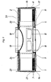
- the container 50 consists of a flat base part 1 and a cake lid-shaped cover part 2, which can be connected to one another approximately airtight. It is also possible to design the bottom part 1 as a cake lid and the lid part 2 flat, since the bottom and top of the container are not fixed from the outset. The strength of the parts must be adjusted appropriately, and it is important, regardless of the shape of the parts, that they can absorb the weight of the enclosed stack.
- the container 50 or 60 consists of plastics suitable for these production processes, e.g. Polystyrene, ABS, rigid PVC, etc.
- All materials are excluded as materials, such as paper, cardboard, foamed polystyrene, etc., as far as these materials are not abrasion-resistant and are unreliable in their handling can detach desired particles that can settle on the recording media.
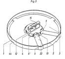
- the container 50 is preferably manufactured using the deep-drawing process. Its bottom part 1 consists of an approximately flat plate 3 with a centrally raised cylinder indentation 4, the outer diameter of which, for easy removal, is somewhat smaller than the inner diameter of the ring cores 11 and a peripheral outer edge 5.
- the ring cores 11 shown have, for example, an essentially horizontally symmetrical, stackable and radially self-locking shape.
- Stack projections 1C projecting upwards and downwards from the horizontal plane engage in the adjacent ring cores 11 and form an axially and radially secure connection.
- any suitable core shape such as the NARTB core according to DIN 45 517 or bowl-like cores, can also be easily transported and handled in such a container.
- the lower stacking projections 10 or extensions of the lowermost ring core 11 can enter a groove 9 arranged around the cylinder impression 4, so that there is a flat placement of the free winding layers on a separate intermediate layer 21.
- These ring-shaped intermediate layers 21 can consist of any suitable material of suitable thickness and are inserted between the band windings 7 and in each case the base or cover part. This protects the individual tape windings and especially the tape edges against mutual contact and rubbing against each other.
- the cover part 2 overlaps the edge 5 of the base part 1 with a widened lower part 17 of the cylinder. linderwand 16, whereby a dustproof seal is obtained.
- the bottom part 1 is provided at least at one point on the edge 5 with a radially directed bulge 6, via which a corresponding bulge 43 of the lid part 2 engages to close the container 50.
- a finger recess 6 'lying on the same radius is provided in the circumference of the cylinder impression 4, the bulge 6 and recess 6' being connected to one another via a radial groove 22.
- Bulge 6 and cut-out 6 ' serve as handle cut-outs for easier insertion and removal of the tape roll 7.
- the two bulges 6 in the present container example also prevent the base and lid parts 1 and 2 from twisting relative to one another and thereby causing tape roll and / or record carrier damage. As can be seen in FIG.
- the annular groove 9 can be interrupted by radial webs 12 and 13 in order to form an anti-rotation device for annular cores with stacking processes.
- the webs 13 can have at least one height such that the difference up to the flat surface of the plate 3 corresponds to the length of the stack extensions of the ring core 11.
- the outer annular groove 14 in the base part 1 can also have interruptions, which arise from the outer recesses 44 for the fastener tapes 8 in the interior of the base part 1.
- Inner ring grooves 24 and outer ring grooves 23 are also provided on the cover part 2, which can also have webs arranged crosswise.
- the cover part 2 has an inwardly extending recess 19 within the inner annular groove 24, which can be produced by deep drawing and which can correspond in diameter to the indentation 4 in the base part 1.
- a handle 15 is expediently provided on the top of the cylinder impression 4 suitably attached, which makes the stack with the base part 1 but without the cover part 2 easy and easy to transport and handle.
- a corresponding handle 15 can also be provided in the recess 19 in the cover part 2 if the closure straps 8 spanning the recess 19 already enable the entire container unit to be carried.
- the recess 19 locking protrusions may the outside of the lid part 2 18 may be provided, which are arranged such that they ylindereingargung in which Z 4 thereon set of the same container 50 fit so that a radial mutual displacement of stacked containers 50 at least more difficult, if not prevented becomes.
- the clear height of the container 50 depends on the shape and dimensions of the base and lid parts 1 and 2 and determines how many tape rolls 7 or recording media can be accommodated and transported therein.
- a vibration-proof design can be realized in that an elastic ring 20, for example made of rubber-elastic material, is attached in the annular groove 24 of the cover part, which exerts a compressive force on the uppermost winding core 11 of the stack for tolerance compensation and for axial fixation when the container 50 is closed.
- the elastic ring 20 can also consist of individual parts, which are provided centrally symmetrically in the annular groove 24.
- the container 50 described above is suitably shaped to be manufactured inexpensively by deep drawing, but it is also possible to manufacture it by injection molding.
- FIGS. 4 to 6 show a container 60 which can advantageously be produced by injection molding. The same parts are provided with the same reference numerals.
- the container 60 consists of a base part 41 and a cover part 42, the outer, slightly conical shape of which is similar to the base and cover parts 1 and 2.
- the base part 41 consists of a flat plate 25 that is flat on the inside.
- An approximately cruciform indentation 26 is formed centrally in this plate 25, which secures the stack of tape rolls 7 against radial displacement.
- the indentation 26 is smaller in diameter than the inner diameter of the ring cores 11.
- the plate 25 is lowered in an annular groove 9 on the circumference of the indentation 26. The depth of the annular groove 9 is equal to or deeper than the length of the projections 10 on the core 11.
- Cross webs 28 are provided at opposite points to prevent rotation, with depressions 29 and spaces 27 for easy and safe insertion and removal of the tape roll 7.
- a handle 15 is attached in a suitable manner on the top of the cross-shaped embossment 26, for example by injection molding, in order to make it easier to carry the bottom part 4'1 with the full stack.
- the bottom part 41 has a step-like raised edge 30 on the outer circumference with a sealing groove 31 for receiving the sealing ring 32. On its underside, the bottom part 41 can be designed with radial and / or annular stiffening or support ribs 33.
- the outer support edge 34 is higher than the ribs 33 and, when stacking identical containers 60, serves to support the base part 41 on a corresponding ring rib 35 on the top side of the lid.
- the base part 41 In the center, within the indentation 26, the base part 41 has an annular shoulder 36 which, when a plurality of containers 60 are stacked, engages in the recess 37 on the cover part 42 to secure them against radial displacement.
- the ribs 34 and 36 can have interruptions for fastener tapes 8. In this embodiment, recesses for fastener tapes 8 have been dispensed with on the outside of the cover.
- the lid part 42 comes with its opening edge 38 to lie on the seal 32, so that a hermetic seal between the bottom and lid parts 41 and 42 is achieved.
- the cover part 42 here has an indentation 37, the outer diameter of which corresponds approximately to that of the indentation 26.
- a handle 15 is advantageously either molded or fastened for carrying the closed container 60 with its contents.
- an elastic ring 39 or individual elastic elements can be attached centrally symmetrically in the annular groove 24 on the circumference of the indentation 37.
- Protective ring foils 21 of suitable thickness made of abrasion-resistant material can be inserted between the individual tape windings 7 and the cover part 42 or the bottom part 41.
Landscapes
- Packaging Of Machine Parts And Wound Products (AREA)
- Packaging Of Annular Or Rod-Shaped Articles, Wearing Apparel, Cassettes, Or The Like (AREA)
- Stackable Containers (AREA)
Applications Claiming Priority (2)
| Application Number | Priority Date | Filing Date | Title |
|---|---|---|---|
| DE8109502U | 1981-03-31 | ||
| DE8109502 | 1981-03-31 |
Publications (1)
| Publication Number | Publication Date |
|---|---|
| EP0062224A1 true EP0062224A1 (fr) | 1982-10-13 |
Family
ID=6726293
Family Applications (1)
| Application Number | Title | Priority Date | Filing Date |
|---|---|---|---|
| EP82102377A Withdrawn EP0062224A1 (fr) | 1981-03-31 | 1982-03-23 | Emballage pour supports d'enregistrement |
Country Status (2)
| Country | Link |
|---|---|
| US (1) | US4457429A (fr) |
| EP (1) | EP0062224A1 (fr) |
Cited By (3)
| Publication number | Priority date | Publication date | Assignee | Title |
|---|---|---|---|---|
| EP0126908A1 (fr) * | 1983-05-27 | 1984-12-05 | International Business Machines Corporation | Récipient pour disques souples |
| US4883178A (en) * | 1987-12-16 | 1989-11-28 | Agfa-Gevaert Aktiengessellschaft | Multiple packing for magnetic tapes wound on cores |
| WO1993011537A1 (fr) * | 1991-11-29 | 1993-06-10 | Ibsm Mehltretter Gmbh | Procede et dispositif pour la manipulation de bobines de bande magnetique plates |
Families Citing this family (10)
| Publication number | Priority date | Publication date | Assignee | Title |
|---|---|---|---|---|
| US4700839A (en) * | 1984-04-24 | 1987-10-20 | 501 TDK Corporation | Package including disk-form magnetic recording mediums |
| US4577756A (en) * | 1984-04-26 | 1986-03-25 | Hennessy Michael P | Protective canister for computer discs |
| US4708246A (en) * | 1986-07-30 | 1987-11-24 | Minnesota Mining And Manufacturing Company | Shipping package for recording tape pancakes |
| US4955471A (en) * | 1987-09-05 | 1990-09-11 | Konica Corporation | Packaging structure for a ring-shaped product |
| DE8900709U1 (de) * | 1989-01-24 | 1989-03-23 | BASF Magnetics GmbH, 67059 Ludwigshafen | Sammelverpackung für auf Kerne gewickelte Magnetbänder |
| USD324950S (en) | 1989-02-10 | 1992-03-31 | Slidex Corporation | Case for receiving magnetic recording mediums |
| US4944398A (en) * | 1989-09-01 | 1990-07-31 | Chrysler Corporation | Stackable nestable tray with central weight bearing hub |
| US5829592A (en) * | 1996-03-25 | 1998-11-03 | Henry Molded Products Inc. | End caps |
| USD439050S1 (en) | 1999-04-06 | 2001-03-20 | 3M Innovative Properties Company | Reusable container half |
| US6820741B2 (en) * | 2003-01-09 | 2004-11-23 | G6 Science Corp. | Disc media and storage and retrieval system |
Citations (6)
| Publication number | Priority date | Publication date | Assignee | Title |
|---|---|---|---|---|
| DE7148615U (de) * | 1900-01-01 | Emi Ltd | Spule fur bandförmige Aufzeichnungs trager | |
| US2859868A (en) * | 1956-05-23 | 1958-11-11 | Ibm | Tape reel package |
| DE1524746A1 (de) * | 1966-06-06 | 1970-07-23 | Disc Pack Corp | Scheibenpaket-Behaelter |
| FR2110653A5 (fr) * | 1970-10-26 | 1972-06-02 | Kodak Pathe | |
| DE2931250A1 (de) * | 1978-07-31 | 1980-02-28 | Minnesota Mining & Mfg | Versand- und lagerbehaelter |
| DE8034894U1 (de) * | 1980-12-31 | 1981-06-04 | Basf Ag, 6700 Ludwigshafen | Verpackung fuer Aufzeichnungstraeger |
Family Cites Families (12)
| Publication number | Priority date | Publication date | Assignee | Title |
|---|---|---|---|---|
| US2631725A (en) * | 1947-07-09 | 1953-03-17 | Ellsworth S Miller | Motion-picture film reel case |
| US2481095A (en) * | 1948-04-24 | 1949-09-06 | Essman Manuel | Fireproof container |
| US2627991A (en) * | 1949-11-21 | 1953-02-10 | Helen M Maersch | Covered serving dish |
| US3212729A (en) * | 1963-04-22 | 1965-10-19 | Gene M Putnam | Wire dispensing apparatus |
| US3369654A (en) * | 1964-10-21 | 1968-02-20 | Morningstar Corp | Reel case with gasket support for reel |
| US3280987A (en) * | 1965-03-11 | 1966-10-25 | Kendall & Co | Tape spindle |
| US3322262A (en) * | 1965-06-01 | 1967-05-30 | Leaming Plastics Inc | Moisture-tight container |
| US3339718A (en) * | 1966-02-28 | 1967-09-05 | Comdata Corp | Reel case |
| US3620475A (en) * | 1968-12-30 | 1971-11-16 | Edward Michael Penn | Data processing magnetic tape cartridge |
| US3612233A (en) * | 1969-07-24 | 1971-10-12 | Memorex Corp | Injection-molded one-piece plastic carrying case with integral hinge and dust seal |
| US3685646A (en) * | 1970-07-13 | 1972-08-22 | Audio Devices Inc | Tape reel container |
| US4162031A (en) * | 1978-04-10 | 1979-07-24 | Summersby E John | Computer tape reel handling device |
-
1982
- 1982-02-26 US US06/352,859 patent/US4457429A/en not_active Expired - Fee Related
- 1982-03-23 EP EP82102377A patent/EP0062224A1/fr not_active Withdrawn
Patent Citations (6)
| Publication number | Priority date | Publication date | Assignee | Title |
|---|---|---|---|---|
| DE7148615U (de) * | 1900-01-01 | Emi Ltd | Spule fur bandförmige Aufzeichnungs trager | |
| US2859868A (en) * | 1956-05-23 | 1958-11-11 | Ibm | Tape reel package |
| DE1524746A1 (de) * | 1966-06-06 | 1970-07-23 | Disc Pack Corp | Scheibenpaket-Behaelter |
| FR2110653A5 (fr) * | 1970-10-26 | 1972-06-02 | Kodak Pathe | |
| DE2931250A1 (de) * | 1978-07-31 | 1980-02-28 | Minnesota Mining & Mfg | Versand- und lagerbehaelter |
| DE8034894U1 (de) * | 1980-12-31 | 1981-06-04 | Basf Ag, 6700 Ludwigshafen | Verpackung fuer Aufzeichnungstraeger |
Cited By (3)
| Publication number | Priority date | Publication date | Assignee | Title |
|---|---|---|---|---|
| EP0126908A1 (fr) * | 1983-05-27 | 1984-12-05 | International Business Machines Corporation | Récipient pour disques souples |
| US4883178A (en) * | 1987-12-16 | 1989-11-28 | Agfa-Gevaert Aktiengessellschaft | Multiple packing for magnetic tapes wound on cores |
| WO1993011537A1 (fr) * | 1991-11-29 | 1993-06-10 | Ibsm Mehltretter Gmbh | Procede et dispositif pour la manipulation de bobines de bande magnetique plates |
Also Published As
| Publication number | Publication date |
|---|---|
| US4457429A (en) | 1984-07-03 |
Similar Documents
| Publication | Publication Date | Title |
|---|---|---|
| EP0320751B1 (fr) | Emballage pour bandes magnétiques enroulées sur des noyaux | |
| DE69315899T2 (de) | Wiederverwendbarer, zweiteiliger Lagerbehälter | |
| EP0086484B1 (fr) | Pochette de protection pour supports d'information en forme de disque à haute densité de mémorisation | |
| EP0587081B1 (fr) | Boîte pour les bobines de bandes magnétiques | |
| EP0525542A2 (fr) | Emballage réutilisable pour un ensemble de bobines | |
| DE69026544T2 (de) | Filmbehälter | |
| EP0475055B1 (fr) | Système d'emballage pour une pluralité de bandes magnétiques enroulées autour d'un noyau | |
| DE3626166A1 (de) | Magnetbandflachspulenpackung | |
| EP0424763B1 (fr) | Emballage pour bandes magnétiques enroulées sur des noyaux | |
| EP0380008B1 (fr) | Conditionnement pour un ensemble de supports d'enregistrement de forme circulaire | |
| US4457429A (en) | Package for recording media | |
| DE7810193U1 (de) | Wickelkern fuer streifenfoermige materalien | |
| DE2931250A1 (de) | Versand- und lagerbehaelter | |
| EP0055356B1 (fr) | Emballage pour supports d'enregistrements | |
| DE2655254C2 (de) | Stapelbare Palette für auf flanschlose Wickelkerne gewickelte Magnetbänder | |
| EP0217254B1 (fr) | Récipient empilable pour support d'enregistrement | |
| EP0575418A1 (fr) | Emballage de groupement pour supports d'enregistrement en forme de bande enroules sur des noyaux. | |
| DE8109502U1 (de) | Verpackung für Aufzeichnungsträger | |
| DE9011867U1 (de) | Sammelverpackung für auf Kerne gewickelte Magnetbänder | |
| EP1434723B1 (fr) | Emballage destine a une bobine de bande magnetique | |
| EP0208062A2 (fr) | Réceptacle pour une pluralité d'objets en forme de disque et élément de ce réceptacle | |
| EP0385068A1 (fr) | Emballage pour bandes magnétiques enroulées sur des noyaux | |
| DE8716580U1 (de) | Sammelverpackung für auf Kerne gewickelte Magnetbänder | |
| DE4025906A1 (de) | Sammelverpackung fuer auf kerne gewickelte magnetbaender | |
| DE8912747U1 (de) | Sammelverpackung für auf Kerne gewickelte Magnetbänder |
Legal Events
| Date | Code | Title | Description |
|---|---|---|---|
| PUAI | Public reference made under article 153(3) epc to a published international application that has entered the european phase |
Free format text: ORIGINAL CODE: 0009012 |
|
| AK | Designated contracting states |
Designated state(s): AT BE CH DE FR GB IT NL SE |
|
| 17P | Request for examination filed |
Effective date: 19821118 |
|
| STAA | Information on the status of an ep patent application or granted ep patent |
Free format text: STATUS: THE APPLICATION HAS BEEN WITHDRAWN |
|
| 18W | Application withdrawn |
Withdrawal date: 19841019 |
|
| REG | Reference to a national code |
Ref country code: GB Ref legal event code: 732 |
|
| RIN1 | Information on inventor provided before grant (corrected) |
Inventor name: HUBER, MANFRED Inventor name: SCHINDLER, ROBERT |