EP0062268A1 - Servofrein pneumatique, notamment pour installations hydrauliques de freinage pour véhicules à moteur - Google Patents
Servofrein pneumatique, notamment pour installations hydrauliques de freinage pour véhicules à moteur Download PDFInfo
- Publication number
- EP0062268A1 EP0062268A1 EP19820102597 EP82102597A EP0062268A1 EP 0062268 A1 EP0062268 A1 EP 0062268A1 EP 19820102597 EP19820102597 EP 19820102597 EP 82102597 A EP82102597 A EP 82102597A EP 0062268 A1 EP0062268 A1 EP 0062268A1
- Authority
- EP
- European Patent Office
- Prior art keywords
- booster
- piston
- actuating rod
- master cylinder
- power amplifier
- Prior art date
- Legal status (The legal status is an assumption and is not a legal conclusion. Google has not performed a legal analysis and makes no representation as to the accuracy of the status listed.)
- Granted
Links
- 238000009434 installation Methods 0.000 title description 3
- 230000005540 biological transmission Effects 0.000 claims description 32
- 238000007789 sealing Methods 0.000 claims description 10
- 239000012528 membrane Substances 0.000 claims description 7
- 239000011324 bead Substances 0.000 claims description 5
- 235000010678 Paulownia tomentosa Nutrition 0.000 claims 1
- 240000002834 Paulownia tomentosa Species 0.000 claims 1
- 238000010276 construction Methods 0.000 description 4
- 230000004323 axial length Effects 0.000 description 3
- 230000018109 developmental process Effects 0.000 description 3
- 238000004519 manufacturing process Methods 0.000 description 3
- 238000005096 rolling process Methods 0.000 description 3
- 230000006835 compression Effects 0.000 description 2
- 238000007906 compression Methods 0.000 description 2
- 241000209035 Ilex Species 0.000 description 1
- 210000000078 claw Anatomy 0.000 description 1
- 239000013013 elastic material Substances 0.000 description 1
- 230000005484 gravity Effects 0.000 description 1
- 239000002655 kraft paper Substances 0.000 description 1
- 239000013585 weight reducing agent Substances 0.000 description 1
Images

Classifications
-
- B—PERFORMING OPERATIONS; TRANSPORTING
- B60—VEHICLES IN GENERAL
- B60T—VEHICLE BRAKE CONTROL SYSTEMS OR PARTS THEREOF; BRAKE CONTROL SYSTEMS OR PARTS THEREOF, IN GENERAL; ARRANGEMENT OF BRAKING ELEMENTS ON VEHICLES IN GENERAL; PORTABLE DEVICES FOR PREVENTING UNWANTED MOVEMENT OF VEHICLES; VEHICLE MODIFICATIONS TO FACILITATE COOLING OF BRAKES
- B60T13/00—Transmitting braking action from initiating means to ultimate brake actuator with power assistance or drive; Brake systems incorporating such transmitting means, e.g. air-pressure brake systems
- B60T13/10—Transmitting braking action from initiating means to ultimate brake actuator with power assistance or drive; Brake systems incorporating such transmitting means, e.g. air-pressure brake systems with fluid assistance, drive, or release
- B60T13/24—Transmitting braking action from initiating means to ultimate brake actuator with power assistance or drive; Brake systems incorporating such transmitting means, e.g. air-pressure brake systems with fluid assistance, drive, or release the fluid being gaseous
- B60T13/46—Vacuum systems
- B60T13/52—Vacuum systems indirect, i.e. vacuum booster units
- B60T13/565—Vacuum systems indirect, i.e. vacuum booster units characterised by being associated with master cylinders, e.g. integrally formed
Definitions
- the invention relates to a pneumatic power booster, in particular for hydraulic motor vehicle brake systems, with an booster housing fastened to a master cylinder, an booster piston which can be moved from a rest position in the direction of the master cylinder, a valve device carried by the booster piston for controlling the pressure prevailing in a working chamber and one Reaction device which, when actuated, adds the force exerted on an actuating rod connected to the control element of the valve device and led out of the booster housing to the force emitted by the booster piston in a predetermined ratio and directs both forces to the piston of the master cylinder.
- a known power amplifier of this type (DE-OS 29 22 299) the actuating rod protrudes from the booster housing on the side facing away from the master cylinder and is pressed into the booster housing to actuate the power booster.
- the amplifier housing is on the side of the operating rod attached to a floor panel of a vehicle.
- This arrangement entails that the amplifier housing is loaded not only by the compressive forces but also by the actuating force introduced on the actuating rod.
- a slotted tube is provided in its interior which connects the two end walls of the booster housing to one another and transmits the forces occurring between the master cylinder and the housing fastening.
- this design is complex and expensive. It also reduces the effective working area of the booster piston.
- a power booster for a hydraulic motor vehicle brake system is also known (DE-PS 543 640), in which the booster housing is attached to the open end of the master cylinder and the booster piston is rigidly connected to a first piston of the master cylinder via a push rod.
- the actuating rod protrudes from the bottom of the master cylinder and is connected to a second piston which is arranged at a distance from the first piston of the master cylinder.
- the valve device is arranged between the end of the actuating rod and the brake pedal and is connected to a working chamber of the power amplifier via a hose line running parallel to the master cylinder.
- a reaction device is not provided in this known power amplifier.
- the booster housing is arranged on the bottom of the master cylinder and the booster piston is connected to the piston of the master cylinder by a tube.
- the actuating rod is arranged inside the tube.
- the actuating rod penetrates the piston of the master cylinder and the tube and is supported on the booster piston via a reaction device formed by levers.
- the amplifier housing is only loaded by the pressures that prevail in its interior. The pressure forces introduced on the actuating rod are absorbed directly by the housing of the master cylinder and supported on the housing attachment.
- the considerable construction effort of the master cylinder and the inevitable enlargement of its diameter are disadvantageous, so that part of the reduction in the weight of the amplifier housing which can be achieved with this type of construction is consumed by the greater weight of the master cylinder.
- the invention has for its object to provide a power amplifier of the type mentioned, in which the amplifier housing is relieved of the operating forces and which is characterized by a simple structure and low manufacturing costs.
- a force transmission element is axially displaceably guided in the master cylinder, which projects axially into the booster housing and is supported directly or indirectly on the piston of the master cylinder in the actuating direction, that the actuating rod is arranged essentially parallel to the force transmission element and laterally next to the master cylinder is led out of the amplifier housing and that at the free end of the power transmission an arm element is supported, which extends transversely to the operating rod extends to the power transmitting member and transmits the initiated actuating force on the actuating rod on the K raftübertragungselement.
- the power amplifier according to the invention is further characterized by a small axial length. While in conventional power amplifiers the axial length is determined by three times the working stroke, in the power amplifier according to the invention the arrangement of the actuating rod parallel to the master cylinder means only twice the working stroke for the axial length.
- the force transmission element forms a guide and bearing for the booster piston.
- the force transmission element preferably consists of a sleeve which engages around one end at a pin at the end of the piston of the master cylinder and with its other end receives a rod fastened to the booster piston. This configuration facilitates the manufacture and installation of the power transmission element.
- An advantageous embodiment of the power amplifier according to the invention with a very short overall length is achieved in that the force transmission element is rigidly connected to the arm and is movable relative to the piston of the master cylinder.
- the reaction device can be arranged within the force transmission element and therefore does not require any additional installation space. This results in a simple construction if the reaction device is arranged between a stop surface of the force transmission element and the booster piston on the one hand and the piston of the master cylinder on the other.
- the reaction device can advantageously consist of a rubber disc which lies within the force transmission element and can be placed with an end face on the pin of the piston of the master cylinder and with the other end face on a ring fastened in the sleeve and on the head of the rod of the booster piston.
- the rubber washer simultaneously forms the required seal between the piston of the master cylinder and the power transmission element.
- Another advantageous embodiment of the invention may consist in the arm being movably mounted on the force transmission element rigidly connected to the piston of the master cylinder.
- the force transmission element then forms a push rod which transmits the forces from the reaction device to the piston of the master cylinder.
- a simplification of the Power amplifier according to the invention can be achieved in that the arm is a pivotally mounted lever which forms the reaction device.
- the lever is preferably formed by a plate which is mounted with a central opening on the rod of the working piston and which engages around the actuating rod with a forked end. In this way, a clamp-free storage for the lever is created, which does not require any additional components.
- the plate has transverse ribs projecting from the plane of the plate in the area of the support points on the force transmission element, booster piston and actuating rod, which form the bearing surfaces.
- the pivoting movement of the lever in the actuating direction is preferably limited by a stop.
- the stop can advantageously be formed by a further arm rigidly connected to the force transmission element, the end of which engages around the actuating rod.
- the further arm advantageously also forms a stop in the brake release direction for the actuating rod.
- the V is erfflerkolben according to the invention supported on the lever in its Fl ä chenhisto p unk t.
- the resulting force from the pressure acting on the booster piston passes through the support surface on the lever, so that no tilting moment can arise.
- the lever also does not cause a tilting moment as long as the booster force and the actuating force are in equilibrium, since the sum of the two forces are transmitted from the lever in the central axis of the force transmission element to the latter.
- the end of the lever which cooperates with the actuating rod is supported on a spring in the brake release direction and in the rest position of the booster there is play between the adjacent support surfaces on the lever and actuating rod, the size of which corresponds to the control path for actuating the booster .
- the lever is prevented from acting on the actuating rod in the initial phase of actuation of the power amplifier, so that the actuation of the power amplifier requires only a small actuation force.
- the spring can be formed in a simple manner by a bead of the sealing ring which surrounds the actuating rod and is arranged in the opening of the booster piston.
- a particularly simple and advantageous embodiment of the invention consists in that the actuating rod is hollow and forms the control piston of the valve device with its amplifier-side end.
- the pressure medium for actuating the booster can be supplied through the hollow actuating rod, so that an additional connecting line is not required.
- a particularly simple construction of the valve housing can be achieved according to a further embodiment of the invention in that the actuating rod penetrates the booster piston and the valve device coaxial to the actuating rod on the side of the booster remote from the master cylinder piston is arranged.
- the actuating rod is preferably guided in an elastic sealing ring in the wall of the booster piston and the valve housing surrounds the end of the actuating rod with radial play. This measure avoids tight manufacturing tolerances and ensures that the actuating rod can be moved easily.
- valve housing is preferably attached to the booster piston by means of a pin projecting axially from the end face of the valve housing, which is fastened in an opening in the booster piston.
- a connecting channel runs from the valve device to the low-pressure chamber in the pin.
- the end of the actuating rod forming the control piston can be guided in the valve housing and the valve housing can be pivotably mounted on the booster piston.
- the valve housing can then follow the movements of the actuating rod, the alignment of the valve housing and actuating rod required for the function of the valve device being maintained.
- a pivotable mounting of the valve housing is achieved in a simple manner in that two pins of the valve housing engage in elastic rings in the wall of the booster piston.
- a pin preferably lies in the central axis of the valve housing and forms a sleeve for guiding the actuating rod.
- the actuating rod is guided in an axially parallel bore of the master cylinder.
- transverse forces are exerted by a can come with the actuating rod connected actuating device, received directly from the housing of the master cylinder and kept away from the guide of the power transmission element.
- the bore in the master cylinder forms an inlet chamber for the pressure medium for actuating the power amplifier, the hollow actuating rod having a lateral inlet opening for the pressure medium within the inlet chamber.
- This arrangement of the inlet chamber has the further advantage that the pressure medium can be supplied via a connection fixed to the housing, so that the power amplifier can also be operated with compressed air in a simple manner.
- the actuating rod can be moved transversely to its longitudinal axis with respect to the master cylinder and the booster housing, it can be sealed in the wall of the booster housing according to the invention by means of a roller membrane which projects into the booster housing, forms an inlet chamber for the pressure medium and at its open end by one Air filter is closed.
- This development of the invention is particularly suitable for supplying the atmospheric air in power amplifiers which are operated with negative pressure.
- a simple mounting of the actuating rod outside of the amplifier housing can also be carried out according to the invention by means of a pivotally articulated lug which is articulated to the actuating rod.
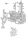
- the power amplifier shown in Fig. 1 is provided for a hydraulic brake system of a motor vehicle. It comprises a hydraulic master cylinder 1, which is screwed with a mounting flange 2 arranged on the cylinder base to a wall 3 of the motor vehicle separating the engine compartment from the passenger compartment. At its open end, the master cylinder 1 carries an amplifier housing 4, which is composed of the housing shells 5 and 6. The housing shell 5 is fastened to a flange 7 of the master cylinder 1 and has a central opening into which the end 8 of the master cylinder 1 projects.
- the master cylinder 1 is designed in a conventional manner as a tandem cylinder. A sectional view of its left section was therefore omitted. The end 8 of the master cylinder 1 is shown in section to make the deviations from the usual design clear.
- a piston 10 is arranged, which is sealed to the pressure chamber 11 by means of a sleeve 12.
- a return spring 13 holds the piston 10 by means of a rod 14 on a stop, not shown, formed in the master cylinder 1.
- a compensating bore 15 and a follow-up bore 16 connect the cylinder bore 9 to a connection 17 for a refill container.
- the piston 10 has at its amplifier end a pin 18 which forms a sliding guide for a cylindrical sleeve 19.
- the outer diameter of the sleeve 19 is adapted to the diameter of the cylinder bore 9.
- the left end of the sleeve projects into the cylinder bore 9.
- a seal arrangement 20 at the end 8 of the master cylinder 1 ensures that the cylinder bore 9 and the booster housing 4 are separated from the cylinder bore 9 on the outer surface of the sleeve 19 in a pressure-tight manner.
- a rubber washer 21 is arranged, which abuts the pin 18.
- a reaction ring 22 fastened in the sleeve 19 and a rod 23 are arranged, which is displaceably mounted in the sleeve by means of a slide ring 25.
- the head 24 at one end of the rod 23 slides through the reaction ring 22 and rests with its end face on the rubber disk 21.
- a clearance x is provided between the reaction ring 22 and the rubber disk 21 in the illustrated rest position of the power amplifier.
- the rubber disc 21 forms with the components surrounding it the reaction device of the power amplifier. At the same time, it seals the gap between the sleeve 19 and the pin 18 to the amplifier housing.
- the booster piston 26 is attached, which carries a rolling membrane 27, the outer edge 28 of which is tightly clamped between the housing shells 5, 6.
- the booster piston 26 divides the booster housing into a low pressure chamber 29 and a working chamber 30.
- the booster piston 26 On its side facing the working chamber 30, the booster piston 26 carries a valve device 31 for controlling the pressure in the working chamber 30.
- the housing 32 of the valve device 31 is formed by an annular disc, the central bore 33 of which is connected to the working chamber 30 via a radial groove 34.
- the central bore 33 is widened by two annular step surfaces 35, 36. The inner edge of the step surface 35 forms a valve seat 37.
- a membrane-like closure element 41 is held pressure-tight by a cover 38 fastened in the enlarged end of the central bore 33.
- the housing 32 is fastened to the booster piston 26 by a pin 39 which passes through a through opening in the rolling membrane 27 and the booster piston 26 and is held on the booster piston 26 with projecting claws.
- a second pin of the same design is not visible in the drawing.
- An axial channel 40 leads through the pin 39 and opens into the stepped surface 35 radially outside the valve seat 37.
- the low-pressure channel 29 is connected to the working chamber 30 through the channel 40, the central bore 33 and the groove 34.
- the closure element 41 lies against a sealing surface on the extended end 45 of an actuating rod 42 which projects into the central bore and is supported in this position by one on the cover 38 Compression spring 43 held.
- the actuating rod 42 is hollow and forms a channel through which the pressure medium for actuating the power amplifier, the atmospheric air, is supplied to the valve device 31.
- the end 45 passes through an opening in the booster piston 26 and is slidably guided in this opening by a sealing ring 44 formed in one piece with the rolling diaphragm.
- the actuating rod 42 passes through an opening in an arm 47 formed on the sleeve 19, on which it is supported in the actuating direction with the step surface formed by the enlarged end 45.
- the section 46 crosses the low-pressure chamber 29 and is guided outside the booster housing 4 in an axially parallel bore 48 of the master cylinder 1.
- a pull tab 50 is articulated, which is connected to a brake pedal 51 which is pivotally mounted in a bearing block 52 fixed to the vehicle.
- the bore 48 is sealed off from the low-pressure chamber 29 by a sliding seal 53 which spans the section 46 of the actuating rod.
- Sliding guide ring 54 is arranged in the opposite end of bore 48.
- the central region of the bore 48 has a larger diameter than the section 46 of the actuating rod 42, which creates an annular space which forms an inlet chamber 55 for the atmospheric air, which enters the inlet chamber 55 via an air filter 56 and an inlet bore 57.
- the actuating rod has an opening 58 inside the inlet chamber 55, through which the air reaches the interior of the actuating rod.
- the end 49 is sealed airtight.
- Fig. 1 the booster is shown in its rest position.
- the booster piston 26 is pressed by a return spring 59 against stops 60 on the housing shell 6.
- Another return spring 61 is supported on the arm 47 and holds it in abutment against a stop ring 62 which is mounted on the end 45 of the actuating rod 42 and is supported on the sealing ring 44.
- the low-pressure chamber 29 is connected via a connection 63 to a low-pressure source, preferably the intake duct of the vehicle engine.
- the pressure in the low-pressure chamber 29 propagates into the working chamber 30 via the valve device 31.
- the atmospheric air passes through the actuating rod 42 to the closure element 41 and through an opening 64 into the space 65 between the closure element 41 and the cover 38. As a result, the atmospheric air assists the compression spring 43 so that it can be easily constructed.
- the piston 10 is actuated via the actuating rod 42, the arm 47 and the sleeve 19, which is supported directly on the piston 10 with its end on the master cylinder side.
- the leadership of the actuating rod 42 and the sleeve 19 on the master cylinder 1 is dimensioned so that Clamping forces can be avoided.
- the booster piston 26 can remain in its rest position at the stops 60, so that the return spring 59 does not have to be tensioned.
- the brake booster shown in FIG. 2 coincides in many parts with the brake booster shown in FIG. 1. As far as the same reference numerals have been used as in FIG. 1, the above description is therefore also applicable to this exemplary embodiment.
- the sleeve 19 is rigidly attached to the pin 18 of the piston 10, with a sealing ring 67 sealing the gap between the sleeve 19 and the pin 18.
- a lever 68 which is formed by a plate and has a central opening 69 through which the rod 21 extends for mounting the lever 68.
- One end of the lever 68 forms a fork 70 which engages around the section 46 of the actuating rod 42.
- the other end of the lever 68 is bent toward the booster piston 26, whereby a transverse rib 71 is created with which the lever 68 bears against the booster piston 26.
- transverse rib 72 With a further transverse rib 72 crossing the opening 69, the lever 68 bears against the end of the sleeve 19 formed by the arm 47, and a transverse rib 73 formed on the fork 70 forms the contact surface for the step surface on the enlarged end 45 of the actuating rod 42
- the transverse ribs 71, 72, 73 are parallel to one another.
- the lever 68 forms the reaction device of the booster, and transmits the actuating forces from the actuating rod 42 and the V erorgrkolben 26 on the sleeve 19th
- a rubber ring 74 is arranged, on which the lever 68 with its fork 70 rests in the rest position shown.
- the rubber ring 74 causes a clearance x to be present between the step surface on the actuating rod and the transverse rib 73 which is dimensioned so large that the end 45 of the actuating rod 42 lifts off the closure element 41 when the brake pedal 51 is actuated before the stepped surface of the actuating rod 42 comes to rest on the transverse rib 73.
- This enables the booster to be actuated with a low actuating force, since in the initial stage of actuation the forces occurring on the fork 70 of the lever 68 are initially absorbed by the rubber ring 74.
- the ratio of the actuating force introduced on the actuating rod to the amplifying force exerted by the booster piston is determined by the length of the lever arms of the lever 68.
- the return spring 61 is supported on a spring plate 75 which is rigidly connected to the actuating rod 42. The end position of the actuating rod 42 is determined by striking the spring plate 75 on the arm 47.
- the lever 68 comes into contact with the arm 47 so that the piston 10 can be actuated directly by the actuating rod 42.
- the guidance of the sleeve 19 over the piston 10 is sufficient to support the transverse forces which occur during such an emergency actuation without jamming.
- the booster housing 4 is in the passenger compartment and the master cylinder 1 in the engine compartment.
- the power amplifier is screwed to the rear side of the flange 7 of the master cylinder 1, which is used to fasten the amplifier housing 4, to the wall 3 of the vehicle.
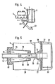
- the brake pedal 51 for actuating the booster is pivotally attached to the master cylinder 1 and the actuating rod 42 is articulated directly on the brake pedal 51. This articulation leads to a pivoting movement of the actuating rod 42, which is made possible by the mounting of the actuating rod 42 and the valve device 31 shown in FIG. 5.
- the housing 32 of the valve device 31 has a central pin 76, in the central bore of which the end 45 of the actuating rod 42 is guided and sealed.
- the pin 76 extends through an opening in the booster piston 26 and is integral with one held with the roll membrane formed bead 77.
- the bead 77 allows a limited pivoting movement of the housing 32.
- a second pin, not shown in FIG. 5, containing the channel 40 is held in the same way by a bead in the booster piston 26, so that both pins have a pivot axis in the direction of view for one Form pivoting movement of the housing 32.
- This mounting allows the housing 32 to follow the pivoting movements of the actuating rod 42, so that the required alignment of the valve seats at the end of the actuating rod 42 and in the housing 32 is maintained and the function of the valve device is ensured.
- the diameter of the inlet opening is considerably larger than the outer diameter of the actuating rod 42.
- a roller membrane 78 is provided for sealing, which has one end at the inlet opening 79 of the housing shell 5 is attached and the other end is attached to the operating rod 42 within the low pressure chamber.
- the interior of the roller membrane 78 forms an inlet chamber 80 in which the opening 58 is arranged in the actuating rod 42.
- the atmospheric air is admitted to the inlet chamber 80 through an air filter 81 which is fastened to the inlet opening 79 by means of a retaining ring 82 and surrounds the actuating rod.
- the air filter is made of an elastic material so that it can follow the movements of the operating rod.
Landscapes
- Engineering & Computer Science (AREA)
- Transportation (AREA)
- Mechanical Engineering (AREA)
- Braking Systems And Boosters (AREA)
Applications Claiming Priority (2)
| Application Number | Priority Date | Filing Date | Title |
|---|---|---|---|
| DE3113708 | 1981-04-04 | ||
| DE19813113708 DE3113708A1 (de) | 1981-04-04 | 1981-04-04 | Pneumatischer kraftverstaerker, insbesondere fuer hydraulische kraftfahrzeug-bremsanlagen |
Publications (2)
| Publication Number | Publication Date |
|---|---|
| EP0062268A1 true EP0062268A1 (fr) | 1982-10-13 |
| EP0062268B1 EP0062268B1 (fr) | 1984-11-28 |
Family
ID=6129393
Family Applications (1)
| Application Number | Title | Priority Date | Filing Date |
|---|---|---|---|
| EP19820102597 Expired EP0062268B1 (fr) | 1981-04-04 | 1982-03-27 | Servofrein pneumatique, notamment pour installations hydrauliques de freinage pour véhicules à moteur |
Country Status (2)
| Country | Link |
|---|---|
| EP (1) | EP0062268B1 (fr) |
| DE (1) | DE3113708A1 (fr) |
Cited By (4)
| Publication number | Priority date | Publication date | Assignee | Title |
|---|---|---|---|---|
| EP0181487A1 (fr) * | 1984-11-05 | 1986-05-21 | Allied Corporation | Assemblage d'actionnement compact pour freins assistés |
| WO2000066404A1 (fr) * | 1999-04-29 | 2000-11-09 | ZF Lemförder Metallwaren AG | Mecanisme de pedale de frein pour vehicules automobiles |
| US6898995B1 (en) * | 1999-06-17 | 2005-05-31 | Continental Teves Ag & Co. Ohg | Actuation device for a motor vehicle |
| WO2016188737A1 (fr) * | 2015-05-28 | 2016-12-01 | Continental Teves Ag & Co. Ohg | Servofrein pneumatique |
Families Citing this family (4)
| Publication number | Priority date | Publication date | Assignee | Title |
|---|---|---|---|---|
| DE3833550A1 (de) * | 1988-10-01 | 1990-04-05 | Teves Gmbh Alfred | Bremsdruckgeber insbesondere fuer die bremsanlage eines kraftfahrzeuges |
| DE3908805A1 (de) * | 1989-03-17 | 1990-09-20 | Teves Gmbh Alfred | Bremskraftverstaerker |
| DE3923459A1 (de) * | 1989-07-15 | 1991-01-17 | Teves Gmbh Alfred | Betaetigungseinheit fuer eine hydraulische kraftfahrzeugbremsanlage |
| DE4127001A1 (de) * | 1991-08-16 | 1993-02-18 | Teves Gmbh Alfred | Betaetigungseinheit fuer hydraulische bremsanlagen |
Citations (5)
| Publication number | Priority date | Publication date | Assignee | Title |
|---|---|---|---|---|
| US2900962A (en) * | 1953-12-18 | 1959-08-25 | Kelsey Hayes Co | Booster brake mechanism |
| GB860202A (en) * | 1958-08-13 | 1961-02-01 | Dewandre Co Ltd C | Improvements in or relating to vacuum braking systems |
| GB860516A (en) * | 1958-08-13 | 1961-02-08 | Dewandre Co Ltd C | Improvements in or relating to air pressure braking systems |
| DE1630668A1 (de) * | 1966-12-12 | 1972-03-23 | Kelsey Hayes Co | Hydraulisches Fahrzeug-Bremssystem |
| DE2949811A1 (de) * | 1978-12-12 | 1980-07-03 | Lucas Industries Ltd | Durch hilfskraft betaetigbare hauptzylinder-anordnung fuer fahrzeug-bremsanlagen |
-
1981
- 1981-04-04 DE DE19813113708 patent/DE3113708A1/de active Granted
-
1982
- 1982-03-27 EP EP19820102597 patent/EP0062268B1/fr not_active Expired
Patent Citations (5)
| Publication number | Priority date | Publication date | Assignee | Title |
|---|---|---|---|---|
| US2900962A (en) * | 1953-12-18 | 1959-08-25 | Kelsey Hayes Co | Booster brake mechanism |
| GB860202A (en) * | 1958-08-13 | 1961-02-01 | Dewandre Co Ltd C | Improvements in or relating to vacuum braking systems |
| GB860516A (en) * | 1958-08-13 | 1961-02-08 | Dewandre Co Ltd C | Improvements in or relating to air pressure braking systems |
| DE1630668A1 (de) * | 1966-12-12 | 1972-03-23 | Kelsey Hayes Co | Hydraulisches Fahrzeug-Bremssystem |
| DE2949811A1 (de) * | 1978-12-12 | 1980-07-03 | Lucas Industries Ltd | Durch hilfskraft betaetigbare hauptzylinder-anordnung fuer fahrzeug-bremsanlagen |
Cited By (6)
| Publication number | Priority date | Publication date | Assignee | Title |
|---|---|---|---|---|
| EP0181487A1 (fr) * | 1984-11-05 | 1986-05-21 | Allied Corporation | Assemblage d'actionnement compact pour freins assistés |
| WO2000066404A1 (fr) * | 1999-04-29 | 2000-11-09 | ZF Lemförder Metallwaren AG | Mecanisme de pedale de frein pour vehicules automobiles |
| US6615684B1 (en) | 1999-04-29 | 2003-09-09 | ZF Lemförder Metallwaren AG | Brake pedal assembly for motor vehicles |
| US6898995B1 (en) * | 1999-06-17 | 2005-05-31 | Continental Teves Ag & Co. Ohg | Actuation device for a motor vehicle |
| WO2016188737A1 (fr) * | 2015-05-28 | 2016-12-01 | Continental Teves Ag & Co. Ohg | Servofrein pneumatique |
| US11760327B2 (en) | 2015-05-28 | 2023-09-19 | Continental Teves Ag & Co. Ohg | Pneumatic brake booster |
Also Published As
| Publication number | Publication date |
|---|---|
| DE3113708C2 (fr) | 1991-02-21 |
| EP0062268B1 (fr) | 1984-11-28 |
| DE3113708A1 (de) | 1982-10-21 |
Similar Documents
| Publication | Publication Date | Title |
|---|---|---|
| DE3013456C2 (fr) | ||
| DE1188965B (de) | Druckmittelbetaetigter Servomotor zum Steuern einer Vorrichtung, insbesondere einer Kraftfahrzeug-Bremsvorrichtung | |
| DE2834510A1 (de) | Fluiddruck-verstaerker | |
| DE3024967C2 (fr) | ||
| EP0062268B1 (fr) | Servofrein pneumatique, notamment pour installations hydrauliques de freinage pour véhicules à moteur | |
| DE2014236C3 (de) | Bremskraftverstärker für Fahrzeuge | |
| DE3806401A1 (de) | Bremskraftverstaerker | |
| DE3107918C2 (fr) | ||
| DE1455818B1 (de) | Bremsverstaerker fuer eine Zweikreisbremsanlage,insbesondere fuer Kraftfahrzeuge | |
| EP0434782B1 (fr) | Bloc de commande pour circuit de freinage hydraulique d'un vehicule automobile | |
| DE2626542A1 (de) | Vorrichtung zur kontrolle der andrueckkraft eines druckmittelgesteuerten zylinders | |
| DE69101031T2 (de) | Unterdruckbremskraftverstärker. | |
| DE4140066A1 (de) | Betaetigungseinheit fuer eine hydraulische bremsanlage | |
| DE10260190A1 (de) | Bremsverstärkervorrichtung | |
| DE3822261A1 (de) | Bremsbetaetigungseinheit fuer kraftfahrzeuge | |
| DE3704133A1 (de) | Hydraulisch angesteuerte betaetigungseinrichtung fuer kraftfahrzeuge | |
| DE3518288C2 (de) | Bremsdruckgeber mit einem vakuumbetriebenen Bremskraftverstärker und einem Hauptzylinder | |
| DE3728659A1 (de) | Unterdruck-bremskraftverstaerker | |
| DE19718097B4 (de) | Differenzdruckbetätigter Bremskraftverstärker | |
| DE3040731A1 (de) | Bremskraftverstaerker | |
| DE4404334A1 (de) | Betätigungseinheit für eine blockiergeschützte Kraftfahrzeugbremsanlage | |
| DE2541474C2 (de) | Lastabhängige Bremseinrichtung | |
| DE3508838A1 (de) | Hydraulische bremsanlage | |
| DE3412397A1 (de) | Vakuumbetriebener bremskraftverstaerker mit hauptzylinder | |
| DE2828178A1 (de) | Kraftverstaerker fuer fahrzeugbremsanlagen |
Legal Events
| Date | Code | Title | Description |
|---|---|---|---|
| PUAI | Public reference made under article 153(3) epc to a published international application that has entered the european phase |
Free format text: ORIGINAL CODE: 0009012 |
|
| AK | Designated contracting states |
Designated state(s): FR GB IT SE |
|
| 17P | Request for examination filed |
Effective date: 19820805 |
|
| ITF | It: translation for a ep patent filed | ||
| GRAA | (expected) grant |
Free format text: ORIGINAL CODE: 0009210 |
|
| RAP1 | Party data changed (applicant data changed or rights of an application transferred) |
Owner name: ALFRED TEVES GMBH |
|
| AK | Designated contracting states |
Designated state(s): FR GB IT SE |
|
| ET | Fr: translation filed | ||
| PLBE | No opposition filed within time limit |
Free format text: ORIGINAL CODE: 0009261 |
|
| STAA | Information on the status of an ep patent application or granted ep patent |
Free format text: STATUS: NO OPPOSITION FILED WITHIN TIME LIMIT |
|
| 26N | No opposition filed | ||
| ITPR | It: changes in ownership of a european patent |
Owner name: ASSUNZIONE O VARIAZIONE MANDATO;HANS BENNO MAYER |
|
| ITTA | It: last paid annual fee | ||
| PGFP | Annual fee paid to national office [announced via postgrant information from national office to epo] |
Ref country code: GB Payment date: 19920305 Year of fee payment: 11 |
|
| PGFP | Annual fee paid to national office [announced via postgrant information from national office to epo] |
Ref country code: FR Payment date: 19920306 Year of fee payment: 11 |
|
| PGFP | Annual fee paid to national office [announced via postgrant information from national office to epo] |
Ref country code: SE Payment date: 19920330 Year of fee payment: 11 |
|
| PG25 | Lapsed in a contracting state [announced via postgrant information from national office to epo] |
Ref country code: GB Effective date: 19930327 |
|
| PG25 | Lapsed in a contracting state [announced via postgrant information from national office to epo] |
Ref country code: SE Effective date: 19930328 |
|
| GBPC | Gb: european patent ceased through non-payment of renewal fee |
Effective date: 19930327 |
|
| PG25 | Lapsed in a contracting state [announced via postgrant information from national office to epo] |
Ref country code: FR Effective date: 19931130 |
|
| REG | Reference to a national code |
Ref country code: FR Ref legal event code: ST |
|
| EUG | Se: european patent has lapsed |
Ref document number: 82102597.0 Effective date: 19931008 |