EP0062273A1 - Verfahren zur Steuerung eines Schrittmotors - Google Patents
Verfahren zur Steuerung eines Schrittmotors Download PDFInfo
- Publication number
- EP0062273A1 EP0062273A1 EP82102626A EP82102626A EP0062273A1 EP 0062273 A1 EP0062273 A1 EP 0062273A1 EP 82102626 A EP82102626 A EP 82102626A EP 82102626 A EP82102626 A EP 82102626A EP 0062273 A1 EP0062273 A1 EP 0062273A1
- Authority
- EP
- European Patent Office
- Prior art keywords
- duration
- pulses
- pulse
- motor
- period
- Prior art date
- Legal status (The legal status is an assumption and is not a legal conclusion. Google has not performed a legal analysis and makes no representation as to the accuracy of the status listed.)
- Granted
Links
- 238000000034 method Methods 0.000 title claims abstract description 30
- 230000007423 decrease Effects 0.000 claims description 6
- 230000007246 mechanism Effects 0.000 claims description 4
- 230000004044 response Effects 0.000 claims description 3
- 230000000630 rising effect Effects 0.000 claims description 2
- 238000010586 diagram Methods 0.000 description 10
- 230000004907 flux Effects 0.000 description 7
- 238000005259 measurement Methods 0.000 description 6
- 230000008569 process Effects 0.000 description 6
- 241001415961 Gaviidae Species 0.000 description 4
- 238000001514 detection method Methods 0.000 description 4
- 230000008859 change Effects 0.000 description 3
- 230000008878 coupling Effects 0.000 description 3
- 238000010168 coupling process Methods 0.000 description 3
- 238000005859 coupling reaction Methods 0.000 description 3
- 230000032683 aging Effects 0.000 description 1
- 230000008033 biological extinction Effects 0.000 description 1
- 230000033228 biological regulation Effects 0.000 description 1
- 230000002301 combined effect Effects 0.000 description 1
- 238000010276 construction Methods 0.000 description 1
- 230000002349 favourable effect Effects 0.000 description 1
- 238000004519 manufacturing process Methods 0.000 description 1
- 239000003921 oil Substances 0.000 description 1
- 230000009467 reduction Effects 0.000 description 1
- 229920006395 saturated elastomer Polymers 0.000 description 1
- 238000009738 saturating Methods 0.000 description 1
- 238000007493 shaping process Methods 0.000 description 1
- 230000035939 shock Effects 0.000 description 1
- 238000003079 width control Methods 0.000 description 1
Images


Classifications
-
- G—PHYSICS
- G04—HOROLOGY
- G04C—ELECTROMECHANICAL CLOCKS OR WATCHES
- G04C3/00—Electromechanical clocks or watches independent of other time-pieces and in which the movement is maintained by electric means
- G04C3/14—Electromechanical clocks or watches independent of other time-pieces and in which the movement is maintained by electric means incorporating a stepping motor
- G04C3/143—Means to reduce power consumption by reducing pulse width or amplitude and related problems, e.g. detection of unwanted or missing step
Definitions
- the present invention relates to a method for controlling a single-phase stepping motor supplied by a train of bipolar pulses with the load presented by the mechanism of a timepiece. It offers various improvements to the servo system which has been described in patent application EP 0 022 270.
- a supply device making it possible to detect the position of the rotor of a stepping motor relative to the polarity of the driving pulses and to send to said motor a train of long pulses if this polarity is considered incorrect.
- the rotor does not advance one step after having sent a motor pulse of correct polarity, it will receive a predetermined period of time later (a second for example) a new pulse of incorrect polarity and it is from this moment that the system comes into operation, the correction or the catching up taking place by sending to the motor two close pulses of long duration followed by a train of pulses of great width.
- the system proposed in the cited application envisages only two types of pulses: narrow pulses when the torque exerted on the motor is low and broad pulses when this torque has increased beyond a certain limit .
- this couple can take very diverse values due, for example, to one of the following events or the combination of some of these events: change of calendar, friction in the bearings and their wear, aging oils, drop in temperature, influence of an external magnetic field, linear or angular shocks, manufacturing tolerances, etc.
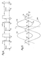
- Figure 1 of this presentation schematically shows a motor whose stator poles are separated by air gaps 1.
- all of the JSab flux from the magnetic rotor 2 passes through the core of the coil 3 to produce at the terminals of this coil a induced voltage Ui when the rotor is moving.
- FIG. 2 shows schematically such a motor where the poles of the stator are joined by isthmus 4. In this case, we see that the flux created by the magnet is divided into a flux i f passing through the isthmus and into a flux ⁇ ab passing through the coil core.
- the pulses referenced n - 2 to n + 4 are the control pulses received by the motor coil.
- the start of each of them is separated by a constant period of time, for example one second, which advances the seconds hand of the watch in steps of one second.
- This clock signal comes from the output of a chain of frequency dividers which is itself supplied by a time base oscillator according to an arrangement which is now well known.
- the first catch-up pulse is in the same direction as the n-1 pulse and the second in the opposite direction so that the wide width pulses T a are somehow substituted to the control pulses n - 1 and n of width T l which were not able to advance the rotor of the motor.
- the duration T a is naturally chosen to be long enough to cause the rotor to progress under the most unfavorable load conditions.
- the graph in Figure 3 exaggerates however this duration T a compared to the duration T l in order to clearly highlight the functioning of the system.
- the invention has the originality, compared to the invention claimed in the application already cited, not to continue with a train of fixed pulses of large width immediately after the catching pulses, but to lengthen somewhat the control pulse of duration T l in duration T 2 and of trying if this new pulse could be of duration long enough to turn the rotor. If this is not the case, the new pulses n + 1 and n + 2 of duration T 2 are followed by two new catch-up pulses of duration T a as illustrated in FIG. 3. In turn, the pulses take-up are followed by new control pulses n + 3, n + 4 of duration T 3 slightly greater than the duration T 2 . If they are able to put the motor in rotation, we continue with the pulses of duration T 3 , otherwise we send the catch-up pulses to then proceed with pulses of width T 4 or T 3 ⁇ T 4 and so on.
- the process which has just been described shows that the duration of the control pulses is adapted to the load imposed on the motor by successive rising levels when the load increases.
- the process therefore makes it possible to save energy and this in even greater proportions than if only two types of pulses were available, as provided for in the cited application.
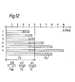
- six different pulses have been chosen whose motor durations range from 3 to 9 ms in successive levels of 0.5 ms for the first three, 1.5 ms for the fourth and fifth and 2 ms for the sixth.
- the duration of the catch-up pulse was chosen at 8 ms. This will appear in more detail when the diagram shown in Figure 12 is explained.
- FIG. 4 presents a second variant of the method according to the invention where, after sending two catch-up pulses, the motor is still supplied with a pair of pulses of the same duration as that which existed before the correction.
- the control pulses n + 1 and n + 2 have the same duration T l as that of the pulses n - 1 and n.
- binding events are of a fleeting nature such that they disappear very quickly.
- An attempt to refuel the motor a second time with pulses the duration of which did not advance its rotor the first time can be fruitful. For, if the attempt succeeds, an increase in consumption will have been avoided due to an unnecessary widening of the control pulses. If the attempt is unsuccessful, the motor is supplied with pulses of longer duration T 2 after having sent the two catch-up pulses.
- This second variant is not limited to the renewed sending of a single pair of pulses of the same duration T l and it will be understood that means can be used to continue supplying the motor with the pulses T l as long as a given number of catch-up pulses will not have been counted in a predetermined interval. Thus, for example, it can be decided that if the rotor has missed its pitch four times for 60 seconds, these missed steps having been followed by four catch-up pulses, the motor is then supplied with pulses of duration T 2 .
- FIG. 5 shows the evolution of the positioning torque Ca and of the mutual torque Cab-such as they are found in a stepping motor.
- the angular positions S ' 2 , S 1 and S 2 are the stable equilibrium positions of the rotor and the positions I' 1 and Il are the unstable equilibrium positions of this rotor. Normally if the rotor takes its step in response to a positive impulse, it goes from position S 1 to position S 2 . In the particular case which has just been mentioned, it is therefore possible for the rotor to stop in position II, which represents only a half-step stroke. Although this position is unstable, it is possible that the rotor is maintained there by the friction which acts on it.
- the rotor will either move back to position S l or move to position 5 2 .
- the new control pulse will have an incorrect polarity and the catch-up pulses T a will make up for the two lost steps.
- the rotor will have caught the lost step itself and no catch-up pulse will be sent to it. The situation is different if the rotor remains fixed in position II when the next pulse occurs. Indeed, this next negative impulse develops the mutual torque -Cab which happens to be in the same direction as the negative positioning torque -Ca.
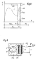
- FIG. 6 shows an arrangement which overcomes the disadvantage cited by proposing according to the invention to send to the motor coil a predetermined period of time after the end of the duration control pulse Tt, a safety pulse of duration T s .
- a pulse of very short duration will suffice for the send either in S 1 or in S 2 .
- a negative safety pulse will bring it back to S 1 and the next normal command pulse will show up as incorrect, which will trigger the two catch-up pulses as explained above.
- a positive safety pulse will bring the rotor to S 2 ; in this case, the next command pulse will appear to be correct and no catch-up will take place.
- a negative safety pulse will be preferred since it takes less energy to bring the rotor from position Il to position S 1 than from position Il to position S 2 .
- a duration between 0.2 and 0.5 ms is chosen for T s and for the period of time separating the end of the control pulse from the safety pulse a duration of the order of 50 ms.
- FIG. 7 shows the device used to obtain a very comfortable voltage Ui even if the motor is of the type with saturable zones.
- the diagram presented differs from the prior art only by the addition of a resistor 40 connected in series with the coil 15 of the motor, which resistor can be short-circuited when the switch 35 is closed.
- this diagram there are between the terminals referenced 41 and 42 alternating control pulses of amplitude U coming from the continuous power source Uplite by the battery when the switches 31-32, respectively 33-34 are closed.
- T RB the duration during which the only coil 15 is connected to terminals 41 and 42
- T x the duration during which the coil 15 - resistor 40 assembly is connected to said terminals
- T cc the duration during which the coil 15 is short-circuited
- U B is the only driving voltage useful to drive the rotor.
- the resistor 40 is connected in series with the coil 15, the switch 35 is open. It is the period of measurement intended to take at the terminals of the coil the induced voltage Ui developed by the motor.
- FIG. 9 shows the behavior of the motor during the measurement period T x .
- the control voltage U is applied to the terminals 41 and 42 of the circuit which includes the coil 3 and the resistor 40 connected in series.
- the value of the resistor 40 is chosen so as to generate in the coil 3 a current LS AT which, in turn, will produce a flux ⁇ b sufficient to saturate the isthmus 4 of the stator.
- the flux ⁇ ab produces an induced voltage across the coil where N b represents the number of turns of the coil.
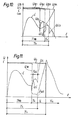
- FIG. 8 shows that at a predetermined time t x of the period T x , the voltage Ui, shown in dashed lines, is of large amplitude as a result of which the motor will continue to be supplied with the same width control pulses T n .
- the induced voltage Ui will be measured in an interval T U i included in the period T x , an interval which may embrace, for example, the last two thirds of the period T x .
- Figure 8 also shows that the current SAT during the measurement period T x is of low amplitude although sufficient however to saturate the isthmus.
- This device which consists in connecting a resistor in series with the motor coil therefore consumes only negligible energy since the necessary current is very low and the time during which this current is developed is reduced to a small fraction of the total time of the command pulse.
- the coil is short-circuited, as is customary to dampen the movement of the rotor.
- FIG. 10 illustrates the phenomenon which has just been explained and shows how the amplitude of the voltage Ui decreases when the pulse U B lengthens.
- the driving pulses of increasing duration U B1 , U B2 and U B3 correspond respectively to the induced voltages Ui l , Ui 2 and Ui 3 , the maximum of said voltages being located on an envelope whose shape is representative of the factor of Cab / i coupling, to the nearest speed.
- the pulse U B4 the figure shows that no induced voltage is detected.
- Figure 11 shows how one proceeds according to the invention to overcome the aforementioned drawback.
- the control pulse U is composed of two driving pulses U B and U c separated by a period T x during which the induced voltage is measured according to the method which has been explained above.
- the width T t of the control pulse U is greater than the duration T n from which the amplitude of the induced voltage Ui would be insufficient or zero, said induced voltage Ui is measured during an interval T U i included in the period T x immediately preceding the end of the period T n .
- the command sequence of the switches shown in Figure 7 is established according to the table below: It should be mentioned that the window method is also perfectly suitable if it is applied to a motor with air gaps (see Figure 1) where the phenomenon of extinction of the induced voltage also exists when the control pulse lengthens. In this case, we can very well not change anything in the diagram in Figure 7 and in the sequence of the table above if we want to use control electronics common to both types of engine. However, the coil of the motor with an open circuit can also be placed, as recommended in application EP 0 022 270, when it is desired to measure the induced voltage. If this is the case, the resistor 40 and the switch 35 shown in FIG. 7 will be deleted and all the switches 31 to 34 will be opened during the duration measurement window T x . It must also be said that if the open circuit voltage Ui is measured in the air gap motor, the graph in FIG. 11 remains the same except for the current i which is canceled out during the period T x .
- FIG. 12 illustrates in an exemplary manner how the width of the control pulse is adapted to the load imposed on the motor and when the induced voltage is measured.
- FIG. 12 also shows the catch-up pulse of duration T a , the width of which is chosen at 8 ms.
- the voltage Ui is compared with a reference voltage in a comparator. If Ui is greater than said reference, a pulse of correct polarity has been sent to the motor and there is no signal at the output of the comparator. The control circuit continues to send pulses of the same duration. If, on the contrary, Ui is smaller than the reference, an incorrect polarity pulse has been sent to the motor and a signal appears at the output of the comparator which forces the control circuit to send two catching pulses then a control pulse train, as explained above.
Landscapes
- Physics & Mathematics (AREA)
- General Physics & Mathematics (AREA)
- Control Of Stepping Motors (AREA)
- Electromechanical Clocks (AREA)
Applications Claiming Priority (2)
| Application Number | Priority Date | Filing Date | Title |
|---|---|---|---|
| CH216581A CH644983GA3 (de) | 1981-03-31 | 1981-03-31 | |
| CH2165/81 | 1981-03-31 |
Publications (2)
| Publication Number | Publication Date |
|---|---|
| EP0062273A1 true EP0062273A1 (de) | 1982-10-13 |
| EP0062273B1 EP0062273B1 (de) | 1986-07-23 |
Family
ID=4227396
Family Applications (1)
| Application Number | Title | Priority Date | Filing Date |
|---|---|---|---|
| EP82102626A Expired EP0062273B1 (de) | 1981-03-31 | 1982-03-29 | Verfahren zur Steuerung eines Schrittmotors |
Country Status (6)
| Country | Link |
|---|---|
| US (1) | US4456866A (de) |
| EP (1) | EP0062273B1 (de) |
| JP (1) | JPS57177296A (de) |
| CA (1) | CA1174060A (de) |
| CH (1) | CH644983GA3 (de) |
| DE (1) | DE3272080D1 (de) |
Cited By (3)
| Publication number | Priority date | Publication date | Assignee | Title |
|---|---|---|---|---|
| EP0108711A1 (de) * | 1982-10-13 | 1984-05-16 | Eta SA Fabriques d'Ebauches | Verfahren und Vorrichtung zur Steuerung eines Schrittmotors |
| EP0182490A1 (de) * | 1984-10-16 | 1986-05-28 | Seiko Instruments Inc. | Schrittmotorgetriebener elektronischer Zeitgeber |
| EP0679967A4 (de) * | 1993-01-18 | 1997-02-26 | Seiko Instr Inc | Zeitgeber. |
Families Citing this family (1)
| Publication number | Priority date | Publication date | Assignee | Title |
|---|---|---|---|---|
| JPS5980147A (ja) * | 1982-10-29 | 1984-05-09 | Rhythm Watch Co Ltd | 時計用小型モ−タ |
Citations (5)
| Publication number | Priority date | Publication date | Assignee | Title |
|---|---|---|---|---|
| FR2388326A1 (fr) * | 1977-04-23 | 1978-11-17 | Seiko Instr & Electronics | Dispositif de detection des conditions de rotation du moteur d'une montre electronique |
| US4158287A (en) * | 1976-08-12 | 1979-06-19 | Citizen Watch Company Limited | Driver circuit for electro-mechanical transducer |
| DE2854084A1 (de) * | 1977-12-20 | 1979-06-21 | Ebauches Electroniques Sa | Anordnung zum nachholen von durch den schrittmotor eines zeitmessgeraetes nicht ausgefuehrten schritten |
| FR2410843A1 (fr) * | 1977-12-02 | 1979-06-29 | Seiko Instr & Electronics | Montre electronique |
| EP0022270A1 (de) * | 1979-07-09 | 1981-01-14 | Societe Suisse Pour L'industrie Horlogere Management Services S.A. | Stellungsdetektor für einen Schrittmotor |
Family Cites Families (1)
| Publication number | Priority date | Publication date | Assignee | Title |
|---|---|---|---|---|
| JPS5385467A (en) * | 1976-12-30 | 1978-07-27 | Seiko Epson Corp | Electronic wristwatch |
-
1981
- 1981-03-31 CH CH216581A patent/CH644983GA3/fr unknown
-
1982
- 1982-03-25 US US06/361,997 patent/US4456866A/en not_active Expired - Fee Related
- 1982-03-29 DE DE8282102626T patent/DE3272080D1/de not_active Expired
- 1982-03-29 EP EP82102626A patent/EP0062273B1/de not_active Expired
- 1982-03-30 CA CA000399806A patent/CA1174060A/en not_active Expired
- 1982-03-31 JP JP57054765A patent/JPS57177296A/ja active Pending
Patent Citations (5)
| Publication number | Priority date | Publication date | Assignee | Title |
|---|---|---|---|---|
| US4158287A (en) * | 1976-08-12 | 1979-06-19 | Citizen Watch Company Limited | Driver circuit for electro-mechanical transducer |
| FR2388326A1 (fr) * | 1977-04-23 | 1978-11-17 | Seiko Instr & Electronics | Dispositif de detection des conditions de rotation du moteur d'une montre electronique |
| FR2410843A1 (fr) * | 1977-12-02 | 1979-06-29 | Seiko Instr & Electronics | Montre electronique |
| DE2854084A1 (de) * | 1977-12-20 | 1979-06-21 | Ebauches Electroniques Sa | Anordnung zum nachholen von durch den schrittmotor eines zeitmessgeraetes nicht ausgefuehrten schritten |
| EP0022270A1 (de) * | 1979-07-09 | 1981-01-14 | Societe Suisse Pour L'industrie Horlogere Management Services S.A. | Stellungsdetektor für einen Schrittmotor |
Non-Patent Citations (1)
| Title |
|---|
| 10e CONGRES INTERNATIONAL DE CHRONOMETRIE, no. 3, 11-14 Sept. 1979, Geneve, CH, M. UEDA et al.: "Adaptive controlled drive system of stepping motor for analog quartz watch", pages 67-72 * |
Cited By (5)
| Publication number | Priority date | Publication date | Assignee | Title |
|---|---|---|---|---|
| EP0108711A1 (de) * | 1982-10-13 | 1984-05-16 | Eta SA Fabriques d'Ebauches | Verfahren und Vorrichtung zur Steuerung eines Schrittmotors |
| US4507599A (en) * | 1982-10-13 | 1985-03-26 | Eta S.A., Fabriques D'ebauches | Method and device for controlling a stepping motor |
| CH649187GA3 (de) * | 1982-10-13 | 1985-05-15 | ||
| EP0182490A1 (de) * | 1984-10-16 | 1986-05-28 | Seiko Instruments Inc. | Schrittmotorgetriebener elektronischer Zeitgeber |
| EP0679967A4 (de) * | 1993-01-18 | 1997-02-26 | Seiko Instr Inc | Zeitgeber. |
Also Published As
| Publication number | Publication date |
|---|---|
| JPS57177296A (en) | 1982-10-30 |
| EP0062273B1 (de) | 1986-07-23 |
| CH644983GA3 (de) | 1984-09-14 |
| US4456866A (en) | 1984-06-26 |
| DE3272080D1 (en) | 1986-08-28 |
| CA1174060A (en) | 1984-09-11 |
Similar Documents
| Publication | Publication Date | Title |
|---|---|---|
| EP0679968B1 (de) | Uhr mit mechanischem Antrieb und mit elektronischer Steuerung | |
| EP0097350B1 (de) | Speiseverfahren eines einphasigen Schrittmotors für eine Uhr | |
| EP0171635B1 (de) | Vorrichtung und Verfahren zur Erkennung der Rotorposition eines Schrittmotors | |
| EP0822470B1 (de) | Elektronisches Uhrwerk, das einen Generator enthält, der von einer Zugfeder getrieben wird | |
| EP0161582A1 (de) | Schrittmotoranordnung | |
| EP0060806B1 (de) | Verfahren zur Reduzierung der Leistungsaufnahme eines Schrittmotors und Vorrichtung zur Durchführung dieses Verfahrens | |
| EP0062273B1 (de) | Verfahren zur Steuerung eines Schrittmotors | |
| EP0022270B1 (de) | Stellungsdetektor für einen Schrittmotor | |
| EP0253153B1 (de) | Verfahren und Vorrichtung zur Kontrolle eines Schrittmotors | |
| EP0135104B1 (de) | Verfahren und Vorrichtung zum Ansteuern eines Schrittmotors | |
| EP0443294A1 (de) | Speiseverfahren für monophasenschrittmotor | |
| EP0087387B1 (de) | Verfahren und Einrichtung zum Steuern eines umsteuerbaren Schrittmotors | |
| FR2478400A1 (fr) | Dispositif de commande d'un moteur electrique | |
| EP0345224B1 (de) | Spannungszuführmethode für Einphasen-Schrittmotoren für Zeitwerke | |
| EP0024737A1 (de) | Detektor für die Fortbewegung eines Schrittmotors | |
| EP0672975A1 (de) | Verfahren zur Versorgung eines einphasigen Schrittmotors | |
| FR2466131A1 (fr) | Moteur pas a pas monophase bipolaire a deux sens de rotation | |
| EP0250862B1 (de) | Verfahren und Vorrichtung zum Steuern eines Schrittmotors | |
| FR2476409A1 (fr) | Piece d'horlogerie avec un dispositif de controle du moteur pas a pas | |
| EP0108711B1 (de) | Verfahren und Vorrichtung zur Steuerung eines Schrittmotors | |
| EP0155661B1 (de) | Regelschaltung für einen Schrittmotor | |
| EP0140089A1 (de) | Verfahren zur Steuerung eines Schrittmotors | |
| FR2483142A1 (fr) | Piece d'horlogerie electronique comportant un circuit de controle du moteur | |
| EP0875807B1 (de) | Elektronisches Uhrwerk gespeist von einem Generator, der durch eine mechanische Energiequelle angetrieben wird | |
| EP0190591A1 (de) | Motorwerk geeignet für hohe Geschwindigkeit |
Legal Events
| Date | Code | Title | Description |
|---|---|---|---|
| PUAI | Public reference made under article 153(3) epc to a published international application that has entered the european phase |
Free format text: ORIGINAL CODE: 0009012 |
|
| AK | Designated contracting states |
Designated state(s): DE FR GB IT |
|
| 17P | Request for examination filed |
Effective date: 19830411 |
|
| RAP1 | Party data changed (applicant data changed or rights of an application transferred) |
Owner name: OMEGA SA |
|
| GRAA | (expected) grant |
Free format text: ORIGINAL CODE: 0009210 |
|
| AK | Designated contracting states |
Kind code of ref document: B1 Designated state(s): DE FR GB IT |
|
| PG25 | Lapsed in a contracting state [announced via postgrant information from national office to epo] |
Ref country code: IT Free format text: LAPSE BECAUSE OF FAILURE TO SUBMIT A TRANSLATION OF THE DESCRIPTION OR TO PAY THE FEE WITHIN THE PRESCRIBED TIME-LIMIT;WARNING: LAPSES OF ITALIAN PATENTS WITH EFFECTIVE DATE BEFORE 2007 MAY HAVE OCCURRED AT ANY TIME BEFORE 2007. THE CORRECT EFFECTIVE DATE MAY BE DIFFERENT FROM THE ONE RECORDED. Effective date: 19860723 |
|
| REF | Corresponds to: |
Ref document number: 3272080 Country of ref document: DE Date of ref document: 19860828 |
|
| PLBE | No opposition filed within time limit |
Free format text: ORIGINAL CODE: 0009261 |
|
| STAA | Information on the status of an ep patent application or granted ep patent |
Free format text: STATUS: NO OPPOSITION FILED WITHIN TIME LIMIT |
|
| 26N | No opposition filed | ||
| PGFP | Annual fee paid to national office [announced via postgrant information from national office to epo] |
Ref country code: GB Payment date: 19910225 Year of fee payment: 10 |
|
| PGFP | Annual fee paid to national office [announced via postgrant information from national office to epo] |
Ref country code: FR Payment date: 19910315 Year of fee payment: 10 |
|
| PGFP | Annual fee paid to national office [announced via postgrant information from national office to epo] |
Ref country code: DE Payment date: 19910321 Year of fee payment: 10 |
|
| PG25 | Lapsed in a contracting state [announced via postgrant information from national office to epo] |
Ref country code: GB Effective date: 19920329 |
|
| GBPC | Gb: european patent ceased through non-payment of renewal fee | ||
| PG25 | Lapsed in a contracting state [announced via postgrant information from national office to epo] |
Ref country code: FR Effective date: 19921130 |
|
| PG25 | Lapsed in a contracting state [announced via postgrant information from national office to epo] |
Ref country code: DE Effective date: 19921201 |
|
| REG | Reference to a national code |
Ref country code: FR Ref legal event code: ST |