EP0062287A2 - Prise pour transmission parallèle de données optiques - Google Patents
Prise pour transmission parallèle de données optiques Download PDFInfo
- Publication number
- EP0062287A2 EP0062287A2 EP82102679A EP82102679A EP0062287A2 EP 0062287 A2 EP0062287 A2 EP 0062287A2 EP 82102679 A EP82102679 A EP 82102679A EP 82102679 A EP82102679 A EP 82102679A EP 0062287 A2 EP0062287 A2 EP 0062287A2
- Authority
- EP
- European Patent Office
- Prior art keywords
- plug
- cable
- funnel
- cover
- cable connector
- Prior art date
- Legal status (The legal status is an assumption and is not a legal conclusion. Google has not performed a legal analysis and makes no representation as to the accuracy of the status listed.)
- Granted
Links
- 230000003287 optical effect Effects 0.000 title claims abstract description 17
- 230000005540 biological transmission Effects 0.000 title claims abstract description 11
- 238000003780 insertion Methods 0.000 claims abstract description 27
- 230000037431 insertion Effects 0.000 claims abstract description 27
- 239000013307 optical fiber Substances 0.000 claims abstract description 7
- 239000004020 conductor Substances 0.000 claims abstract description 5
- 238000005452 bending Methods 0.000 claims description 5
- 229910000831 Steel Inorganic materials 0.000 claims description 3
- 230000001681 protective effect Effects 0.000 claims description 3
- 239000010959 steel Substances 0.000 claims description 3
- 238000006243 chemical reaction Methods 0.000 abstract description 2
- 239000000835 fiber Substances 0.000 description 4
- 230000005693 optoelectronics Effects 0.000 description 3
- 230000008878 coupling Effects 0.000 description 1
- 238000010168 coupling process Methods 0.000 description 1
- 238000005859 coupling reaction Methods 0.000 description 1
- 230000000694 effects Effects 0.000 description 1
- 238000005516 engineering process Methods 0.000 description 1
- 239000003365 glass fiber Substances 0.000 description 1
- 238000009434 installation Methods 0.000 description 1
- 238000002955 isolation Methods 0.000 description 1
- 238000000034 method Methods 0.000 description 1
- 230000002035 prolonged effect Effects 0.000 description 1
- 230000000717 retained effect Effects 0.000 description 1
Images


Classifications
-
- G—PHYSICS
- G02—OPTICS
- G02B—OPTICAL ELEMENTS, SYSTEMS OR APPARATUS
- G02B6/00—Light guides; Structural details of arrangements comprising light guides and other optical elements, e.g. couplings
- G02B6/24—Coupling light guides
- G02B6/42—Coupling light guides with opto-electronic elements
- G02B6/4201—Packages, e.g. shape, construction, internal or external details
- G02B6/4274—Electrical aspects
- G02B6/4284—Electrical aspects of optical modules with disconnectable electrical connectors
Definitions
- the invention relates to a line connector for parallel optical data transmission with a base part with side walls, a cover which can be snapped onto this and at least one insertion opening for an optical fiber cable.
- the object of the present invention is therefore to create a line connector for parallel optical data transmission with an optical cable input and an electrical plug output.
- the cable connector is designed such that the bottom part, which is rectangular in its plug-in area and trapezoidal in the cable feed area, has openings on the three trapezoid sides into which, if necessary, cylindrical insertion funnels which expand towards the inside of the plug can be used, and that several are inserted in the plug-in area , plug modules designed for optoelectrical implementation are arranged next to one another, each of which is connected on the back to individual conductors of the optical waveguide cable and has contact pins on the front for " contain an electrical plug.
- a cable plug for optoelectric data transmission in which the plugging is carried out on the electrical side.
- a connector field can be created which is adapted to the previous electrical plugs, so that the previous electrical interface can be replaced by an opto-electronic one without major conversion effort.
- the optical fiber can be fed in from behind, from above or from below, depending on the space required.
- the cable connector is designed in such a way that the insertion funnels that can be used on the inclined sides of the rear base part are provided with an extended funnel side wall that does not fall below the minimum permissible bending radius of the individual optical waveguides, it is always ensured that the smallest permissible bending radius of the individual optical waveguide is not undercut, so that the transmission properties of the optical waveguide are retained even after prolonged use.
- the insertion funnels can be snapped into the different insertion openings.
- the invention provides that the insertion funnels are provided with a flange which can be used in recesses in the base part.
- a pin running perpendicular to the bottom part is provided, which is supported both on the bottom part and on the cover that can be attached later and thus has a relieving effect.
- a strain relief for the connected light waves Conductor cable can be formed by hanging the steel wire forming the cable core by means of an eyelet on a pin in the center of the connector. Another possibility is that the optical waveguide cable is cast with it after insertion into the insertion funnel.
- the base part can also contain recesses into which projections with lugs snap vertically to the cover.
- a web is provided in the bottom part behind the recesses for the flange of the lateral insertion funnel, which engages with the flange and the extended funnel side part.
- the unused openings for the insertion funnels can be closed with cover parts.
- the base part and the cover can be extended so far that they form a protective collar around the contact pins.
- At least one further module can be provided for receiving a compensation circuit.
- this is a correspondingly dimensioned ohmic resistance.
- holes are provided in addition to the opening for the middle insertion funnel in the base part for attaching a pulling tool.
- lugs are provided on the underside, which snap into recesses 5 of the associated socket.
- the insertion funnel 7 for the cable execution upwards and downwards is the same component and can be used on a cover.
- the first individual fibers lie against an elongated side wall 8 of the funnel; In this way, the minimum bending radius is not exceeded.
- the 20-wire cable is relieved of strain by hanging the steel wire 9, which forms the core of the cable, by means of an eyelet on a pin 10 in the center of the plug, or by pouring the individual spring into the funnel.
- Quadromodule modules as described in German patent application P ... (VPA 81P2026), are mainly used as converter modules.
- 4 transmitter diodes or 4 receive diodes with amplifier circuit are contained in a converter module.
- 8 connecting legs which are designed as contact pins 12, are arranged in two rows in a predetermined grid.
- the bottom and the cover of the line connector are so far advanced that the pins lie between these protective walls 13 and are protected against damage, especially when the connector is pulled.
- the female connector 14 on the printed circuit board is arranged on supports. So that the quadromodule module and the compensation module cannot change their position in the plug during the plugging and unplugging process, they are equipped with retaining lugs 15 which engage in recesses which are present in the base part and in the cover at a grid spacing.
- the cover of the line plug has two extensions with lugs 16 which are perpendicular to the cover surface and which latch in corresponding recesses in the base part 17 when the cover is attached. To remove the extensions are pressed against their spring action inwards until the positive connection no longer exists.
- a tool must be used to pull out the cable connector in various installation cases. This is in two holes 18 are inserted at the rear end of the line connector. It serves as a kind of plug extension.
- Fig. 2 shows a section approximately in. the height of the recesses 17 through the cable connector with rastered cover 2. There are vertical lugs 16 on the cover, which run into corresponding lugs which engage in recesses 17 of the base part 1. The individual fibers 19 of the optical waveguide cable 11 are guided to the five optoelectronic plug-in modules 3.
- optical waveguide cable 7 is brought up to the plug from below.
- the middle and upper opening are free and can be covered with a cover part.
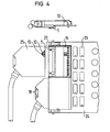
- Fig. 4 shows a specific application.
- the printed circuit board 24, on which integrated components 25 are applied contains two female connectors 14 with corresponding air cover brackets 26.
- the lower cable connector is drawn in and the upper cable connector 27 is drawn.
- FIG. 4 the cross section of a plug which is in the inserted state can be seen, the locking lugs 5 on the base part 1 of the line plug 27 being clearly visible.
Landscapes
- Physics & Mathematics (AREA)
- General Physics & Mathematics (AREA)
- Optics & Photonics (AREA)
- Connector Housings Or Holding Contact Members (AREA)
- Mechanical Coupling Of Light Guides (AREA)
- Optical Couplings Of Light Guides (AREA)
Applications Claiming Priority (2)
| Application Number | Priority Date | Filing Date | Title |
|---|---|---|---|
| DE3113168 | 1981-04-01 | ||
| DE3113168A DE3113168C2 (de) | 1981-04-01 | 1981-04-01 | Leitungsstecker für parallele optische Datenübertragung |
Publications (3)
| Publication Number | Publication Date |
|---|---|
| EP0062287A2 true EP0062287A2 (fr) | 1982-10-13 |
| EP0062287A3 EP0062287A3 (en) | 1982-12-08 |
| EP0062287B1 EP0062287B1 (fr) | 1985-07-24 |
Family
ID=6129065
Family Applications (1)
| Application Number | Title | Priority Date | Filing Date |
|---|---|---|---|
| EP82102679A Expired EP0062287B1 (fr) | 1981-04-01 | 1982-03-30 | Prise pour transmission parallèle de données optiques |
Country Status (3)
| Country | Link |
|---|---|
| EP (1) | EP0062287B1 (fr) |
| JP (1) | JPS6041326B2 (fr) |
| DE (1) | DE3113168C2 (fr) |
Cited By (6)
| Publication number | Priority date | Publication date | Assignee | Title |
|---|---|---|---|---|
| DE3302373A1 (de) * | 1983-01-25 | 1984-07-26 | WAGO Verwaltungsgesellschaft mbH, 4950 Minden | Schaltanlagen-reihenklemme |
| EP0201749A3 (fr) * | 1985-05-14 | 1987-04-22 | Allied Corporation | Connecteur avec un élément opto-électronique amovible |
| EP0677756A3 (fr) * | 1994-04-13 | 1996-05-01 | Framatome Connectors Int | Connecteur à fibre pour câble hybride optique et métallique. |
| EP1180704A3 (fr) * | 2000-08-09 | 2003-08-20 | Siemens Aktiengesellschaft | Connecteur et système pour la connection électrique de supports comprenant des composants électriques dans le domaine des télécommunications |
| WO2006047190A1 (fr) * | 2004-10-22 | 2006-05-04 | Intel Corporation | Connecteur de montage de surface pour des reseaux comprenant des vscel et des photodiodes |
| CN108716961A (zh) * | 2018-06-21 | 2018-10-30 | 迈格仪表(成都)有限公司 | 一种压力变送器 |
Families Citing this family (9)
| Publication number | Priority date | Publication date | Assignee | Title |
|---|---|---|---|---|
| DE8519788U1 (de) * | 1985-07-09 | 1985-10-31 | Albatron Elektronik GmbH, 2000 Hamburg | Vorrichtung zur Verbindung der Schnittstellen insbesondere des Typs V24 selbständiger Schaltwerke von Datenverarbeitungsanlagen |
| DE9001896U1 (de) * | 1990-02-17 | 1991-06-13 | Stribel GmbH, 7443 Frickenhausen | Optoelektronische Einrichtung |
| DE59106807D1 (de) * | 1990-02-17 | 1995-12-07 | Stribel Gmbh | Signalübertragungsleitung. |
| DE9215027U1 (de) * | 1992-11-09 | 1993-01-14 | Inotec electronics GmbH, 7100 Heilbronn | Gehäuse zur elektrischen Verbindung eines Steckverbinders mit einem elektrischen Kabel |
| DE4338732C2 (de) * | 1993-11-12 | 2003-12-11 | Thomas Dandekar | Biosensor (neuer Bauart) |
| DE4443200C1 (de) * | 1994-12-05 | 1996-06-20 | Framatome Connectors Int | Kombinierter LWL-/Metallkabel-Steckverbinder |
| DE10018018A1 (de) * | 2000-04-11 | 2001-10-25 | Delphi Tech Inc | Verbinderteil |
| DE10217579A1 (de) * | 2002-04-19 | 2003-11-13 | Xignal Technologies Ag | Kabel zur Übertragung von Daten sowie Verwendung eines derartigen Kabels |
| CN106991108A (zh) | 2016-09-27 | 2017-07-28 | 阿里巴巴集团控股有限公司 | 一种信息的推送方法及装置 |
Family Cites Families (7)
| Publication number | Priority date | Publication date | Assignee | Title |
|---|---|---|---|---|
| FR973130A (fr) * | 1941-06-20 | 1951-02-07 | Jaeger Ets Ed | Perfectionnements aux dispositifs de connexions électriques multiples |
| US2891132A (en) * | 1955-12-13 | 1959-06-16 | Columbus Mckinnon Chain Corp | Electric hoist control |
| US3170749A (en) * | 1962-06-21 | 1965-02-23 | Bengt J Johanson | Plug assembly |
| DE1790336C3 (de) * | 1967-02-07 | 1979-05-17 | Bunker Ramo Corp., Oak Brook, Ill. (V.St.A.) | Elektrischer Steckverbinder zum Anschluß an ein mehradriges Kabel |
| DE2013884C3 (de) * | 1970-03-23 | 1975-01-23 | Siemens Ag, 1000 Berlin Und 8000 Muenchen | Steckvorrichtung |
| DE2824009A1 (de) * | 1978-06-01 | 1979-12-06 | Harting Elektronik Gmbh | Einrichtung zur zugentlastung fuer griffteile elektrischer steckverbinder |
| DE3008255A1 (de) * | 1979-03-07 | 1980-09-11 | Vero Electronics Ltd | Endverbinder fuer ein lichtleitfaserkabel |
-
1981
- 1981-04-01 DE DE3113168A patent/DE3113168C2/de not_active Expired
-
1982
- 1982-03-30 EP EP82102679A patent/EP0062287B1/fr not_active Expired
- 1982-04-01 JP JP57054751A patent/JPS6041326B2/ja not_active Expired
Cited By (8)
| Publication number | Priority date | Publication date | Assignee | Title |
|---|---|---|---|---|
| DE3302373A1 (de) * | 1983-01-25 | 1984-07-26 | WAGO Verwaltungsgesellschaft mbH, 4950 Minden | Schaltanlagen-reihenklemme |
| EP0201749A3 (fr) * | 1985-05-14 | 1987-04-22 | Allied Corporation | Connecteur avec un élément opto-électronique amovible |
| US4779948A (en) * | 1985-05-14 | 1988-10-25 | Amphenol Corporation | Contact with exchangeable opto-electronic element |
| EP0677756A3 (fr) * | 1994-04-13 | 1996-05-01 | Framatome Connectors Int | Connecteur à fibre pour câble hybride optique et métallique. |
| EP1180704A3 (fr) * | 2000-08-09 | 2003-08-20 | Siemens Aktiengesellschaft | Connecteur et système pour la connection électrique de supports comprenant des composants électriques dans le domaine des télécommunications |
| WO2006047190A1 (fr) * | 2004-10-22 | 2006-05-04 | Intel Corporation | Connecteur de montage de surface pour des reseaux comprenant des vscel et des photodiodes |
| US8412052B2 (en) | 2004-10-22 | 2013-04-02 | Intel Corporation | Surface mount (SMT) connector for VCSEL and photodiode arrays |
| CN108716961A (zh) * | 2018-06-21 | 2018-10-30 | 迈格仪表(成都)有限公司 | 一种压力变送器 |
Also Published As
| Publication number | Publication date |
|---|---|
| DE3113168C2 (de) | 1985-09-12 |
| DE3113168A1 (de) | 1982-10-14 |
| EP0062287B1 (fr) | 1985-07-24 |
| JPS57177114A (en) | 1982-10-30 |
| EP0062287A3 (en) | 1982-12-08 |
| JPS6041326B2 (ja) | 1985-09-17 |
Similar Documents
| Publication | Publication Date | Title |
|---|---|---|
| EP0062287B1 (fr) | Prise pour transmission parallèle de données optiques | |
| DE60100091T2 (de) | Optischer und elektrischer Steckverbinder | |
| DE69930083T2 (de) | Steckverbinder für Kommunikationskabel | |
| DE4121313C2 (de) | Modulares Gebäudeverdrahtungssystem | |
| DE60102615T2 (de) | Zwischensteckerverbindung | |
| DE112009000065B4 (de) | Kabelbaum | |
| DE69736583T2 (de) | Faseroptisches Steckersystem | |
| DE4402837A1 (de) | Flachkabel | |
| DE4441230A1 (de) | Gehäuse mit Vorrichtung zur Halterung von Anschlußkabeln | |
| EP0849840B1 (fr) | Connecteur blindé multipolaire pour câbles | |
| DE8016071U1 (de) | Uebergangsverbindung fuer koaxialkabel | |
| DE8413226U1 (de) | Diodenstecker | |
| DE3012638C2 (de) | Glasfaserkabel mit Mitteln zur Ermöglichung einer Ortung | |
| DE3712467A1 (de) | Koaxialkabel-uebertragungssystem | |
| DE2855742A1 (de) | Kontaktelement fuer selbsttaetig abisolierende verbindungseinrichtung und mit diesem kontaktelement ausgeruestete verbindungseinrichtung | |
| DE69123801T2 (de) | Elektrischer Miniaturstecker | |
| DE3537432C2 (fr) | ||
| DE3527914C2 (fr) | ||
| DE3247803A1 (de) | Elektrooptische verbindungseinrichtung | |
| DE102020114330A1 (de) | Verbindungsdose zur Aufnahme von Anschlussklemmen | |
| DE3932709A1 (de) | Elektrischer steckverbinder | |
| CH681668A5 (fr) | ||
| DE102011089025B4 (de) | USB-Buchse und Verfahren zu deren Herstellung | |
| DE8109413U1 (de) | "Vorrichtung zum Verbinden von Lichtwellenleitern" | |
| EP0584658A2 (fr) | Répartiteur pour armoires blindées contre les interférences électromagnétiques |
Legal Events
| Date | Code | Title | Description |
|---|---|---|---|
| PUAI | Public reference made under article 153(3) epc to a published international application that has entered the european phase |
Free format text: ORIGINAL CODE: 0009012 |
|
| PUAL | Search report despatched |
Free format text: ORIGINAL CODE: 0009013 |
|
| AK | Designated contracting states |
Designated state(s): FR GB IT NL |
|
| AK | Designated contracting states |
Designated state(s): FR GB IT NL |
|
| 17P | Request for examination filed |
Effective date: 19821206 |
|
| ITF | It: translation for a ep patent filed | ||
| GRAA | (expected) grant |
Free format text: ORIGINAL CODE: 0009210 |
|
| AK | Designated contracting states |
Designated state(s): FR GB IT NL |
|
| ET | Fr: translation filed | ||
| PGFP | Annual fee paid to national office [announced via postgrant information from national office to epo] |
Ref country code: NL Payment date: 19860331 Year of fee payment: 5 |
|
| PLBE | No opposition filed within time limit |
Free format text: ORIGINAL CODE: 0009261 |
|
| STAA | Information on the status of an ep patent application or granted ep patent |
Free format text: STATUS: NO OPPOSITION FILED WITHIN TIME LIMIT |
|
| 26N | No opposition filed | ||
| PG25 | Lapsed in a contracting state [announced via postgrant information from national office to epo] |
Ref country code: NL Effective date: 19871001 |
|
| NLV4 | Nl: lapsed or anulled due to non-payment of the annual fee | ||
| GBPC | Gb: european patent ceased through non-payment of renewal fee | ||
| PG25 | Lapsed in a contracting state [announced via postgrant information from national office to epo] |
Ref country code: FR Free format text: LAPSE BECAUSE OF NON-PAYMENT OF DUE FEES Effective date: 19871130 |
|
| REG | Reference to a national code |
Ref country code: FR Ref legal event code: ST |
|
| PG25 | Lapsed in a contracting state [announced via postgrant information from national office to epo] |
Ref country code: GB Effective date: 19881121 |