EP0062342A1 - Einrichtung zum schnellen Beladen von Förderwagen, insbesondere von Lastkraftwagen - Google Patents
Einrichtung zum schnellen Beladen von Förderwagen, insbesondere von Lastkraftwagen Download PDFInfo
- Publication number
- EP0062342A1 EP0062342A1 EP82102905A EP82102905A EP0062342A1 EP 0062342 A1 EP0062342 A1 EP 0062342A1 EP 82102905 A EP82102905 A EP 82102905A EP 82102905 A EP82102905 A EP 82102905A EP 0062342 A1 EP0062342 A1 EP 0062342A1
- Authority
- EP
- European Patent Office
- Prior art keywords
- carriages
- trains
- carriage
- truck
- cable
- Prior art date
- Legal status (The legal status is an assumption and is not a legal conclusion. Google has not performed a legal analysis and makes no representation as to the accuracy of the status listed.)
- Withdrawn
Links
- 230000008021 deposition Effects 0.000 claims 1
- 230000006978 adaptation Effects 0.000 description 2
- 238000000151 deposition Methods 0.000 description 2
- 238000005096 rolling process Methods 0.000 description 2
- 238000004804 winding Methods 0.000 description 2
- 230000005540 biological transmission Effects 0.000 description 1
- 230000008878 coupling Effects 0.000 description 1
- 238000010168 coupling process Methods 0.000 description 1
- 238000005859 coupling reaction Methods 0.000 description 1
- 239000002184 metal Substances 0.000 description 1
- 210000000056 organ Anatomy 0.000 description 1
- 238000002360 preparation method Methods 0.000 description 1
- 230000000284 resting effect Effects 0.000 description 1
Images


Classifications
-
- B—PERFORMING OPERATIONS; TRANSPORTING
- B65—CONVEYING; PACKING; STORING; HANDLING THIN OR FILAMENTARY MATERIAL
- B65G—TRANSPORT OR STORAGE DEVICES, e.g. CONVEYORS FOR LOADING OR TIPPING, SHOP CONVEYOR SYSTEMS OR PNEUMATIC TUBE CONVEYORS
- B65G67/00—Loading or unloading vehicles
- B65G67/02—Loading or unloading land vehicles
- B65G67/04—Loading land vehicles
- B65G67/20—Loading covered vehicles
Definitions
- the invention relates to a rapid charging device for transport vehicles such as trucks, truck trailers, wagons, boats or airplanes.
- the subject of the invention is a loading device for transport vehicles, in particular for trucks, intended to equip a quay or other departure surface against which the truck comes to dock, this device comprising trains of carriages coupled to each other and receiving the containers by means of handling pallets, characterized by the fact that at least a plurality of carriages coupled to each other mounted on guide tracks, comprise translation members forwards or backwards so that they can be inserted or removed of the truck, and of the container support members which can be driven longitudinally so that the containers are transmitted from one carriage to another, the translation members and the support members being able to be moved in opposite directions so that the containers are forced to remain fixed in position while the carriages are moving, and thus the containers are placed on the floor of the vehicle e of transport.
- the train of trolleys can be fitted at the front with an adapter element forming an inclined plane facilitating the depositing of containers.
- the translation member is a hoist actuating a lifter which is provided with one of the carriages, preferably the last, and which also secures the parallel trains of carriages to be driven simultaneously.
- the support member is constituted by series of endless chains fitted individually to the carriages and linked together by drive sprockets, these sprockets or one of them being able to be moved in rotation for the chain drive.
- the drive pinion (s) are moved by the hoist cable, so that the chains and the carriages are driven in opposite directions.
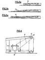
- a charger device comprises a plurality of trains 1, 2, '3 of trolleys arranged in parallel, each trolley such as 4 being able to move by means of wheels or rollers guided in guide grooves 5 dug into the ground.
- This assembly is placed on a platform 6 against which the trucks to be loaded 7 can dock by the tailgate.
- a platform 8 receives tilting guide elements 9 making it possible to make up for the difference in level that may exist between the platform and the platform of the truck.
- Each carriage such as 4 is composed of a welded frame 10 provided with four wheels 11, mounted idly on their axis ensuring the rolling in grooves or guide rails, and comprising at its rear upper part, a pair of pinions 12 to two toothed wheels each for endless roller chains, a pinion being located on each side of the carriage, the two wheels having the same diameter and the same number of teeth.
- the carriages are suitably coupled, for example by means of forks which fit into one another and are joined and articulated by the axis of the toothed wheels.
- Endless chains 13 mesh with the wheels of the head gear and the tail gear, so as to provide by their rollers a rolling surface going from one end to the other of the train of carriages, the first carriage comprising both a head gear and a tail gear.
- a head element or adapter such as 4a, 4b or 4c, of reduced height or with an inclined surface, making it possible to lower a container before placing it on the ground.
- roller chains are intended to receive the containers arranged side by side, by means of pallets schematically represented in phantom lines 26. It will be appreciated that if one of the pairs of sprockets is rotated, the other chains of the same train will also be driven and, as a result, the containers will advance relative to the carriage. However, if the carriage train is in dragged in the opposite direction, the containers will remain stationary and will be placed on the floor of the truck platform while the train of carriages moves backwards.
- the translational movement of the train of carriages is obtained in the following way: the different train of carriages cooperating in the same load are coupled together by a lifting beam 27 engaged across the frames and held in place in any suitable manner. It is thus possible, by exerting a traction force on the spreader or an element of one of the carriages, to simultaneously move all of the associated trains. This effort is obtained by means of a cable 14 fixed at one end to a carriage and which, after passing over guide pulleys 15, is wound on a motorized capstan 16. A return pulley 17 allows, when it is introduced on the cable route, reverse the direction of action on the whole train.
- the movement of the chains is carried out as has been said by driving at least one of the toothed pinions of one of the associated trains.
- the axes of the gears of contiguous carriages, for example the last carriages of the various associated trains can be made integral, so that all the chains are driven from an action on a single carriage of one of the trains .
- This drive is carried out as shown in FIG. 1 and in FIG. 6 by winding the traction cable 14 on a drum 18 which, itself, is connected by endless belt 19 to a pulley 20 mounted on the axis of sprockets 21.
- the pulley 20 is mounted on the axle by means of a freewheel coupler so that the chain is driven only for one direction of travel of the cable, that is to say say in the sense that who pulls the carts out and then move them away from the truck to be loaded.
- the operation of the device is carried out as follows: first of all, the loads are placed on single-sided or two-sided handling pallets resting on the chains of the associated carriage trains for loading, these carriage trains then being on the loading dock. Assume, for example, that two trolley trains correspond to the loading width of the truck intended to receive the load and that, since the pallets are double-sided, a certain interval must be reserved between the surface of the pallet and the loading floor. .
- the operation is carried out in three stages:
- the metal platform 8 attached to the quay supports the connecting elements between a truck 7 and the guides 5, rails or grooves carried by the loading dock 6. These elements consist of flap rails 9 balanced , adjustable in inclination and depth.
- the introduction of the load is facilitated by a gantry 22 equipped with side flaps 23, while the truck is immobilized by wheel guards. 24 also ensuring its positioning to receive the load.
- the capstan 16 ensures, by pulling on the cable 14 pulling directly on a carriage, the advancement of the carriage trains by the spreader 13.
- the loader that is to say the assembly of trains of carriages, entered completely inside the truck, the operator unhooks the cord 14 from the carriage and makes it perform a turn around the return pulley 17, then hangs it up on the carriage.
- the carriages When the capstan 16 turns by winding the cable on its drum, the carriages are pulled towards the pulley 17, that is to say that the loader leaves the truck; at the same time, because the cable 14 is wound around the drum 18, it drives it in rotation, which causes the rotation of the associated pulley and consequently that of the transmission belt 19 and of the pinion axis 20.
- This axis transmits its movement to the homologous axis of the train of attached carriages, this which drives the rotation of the cogwheels and consequently that of the roller chains, the direction of rotation being such that these chains drive the loads and their pallets towards the interior of the truck.
- the speed of withdrawal of the carriages is equal and opposite to that of the chains, so that the first carriage progressively passes under the different loads and that these are deposited on the floor of the truck by the 'through their pallets.
- this adapter element When an adapter element has been placed at the head of the trolley train, to facilitate the depositing of the loads, for example in the case of single-sided pallets, this adapter element is not loaded so that when the trolleys were pushed inside the truck, the last load is still outside.
Landscapes
- Engineering & Computer Science (AREA)
- Aviation & Aerospace Engineering (AREA)
- Mechanical Engineering (AREA)
- Loading Or Unloading Of Vehicles (AREA)
- Handcart (AREA)
Applications Claiming Priority (2)
| Application Number | Priority Date | Filing Date | Title |
|---|---|---|---|
| FR8106855 | 1981-04-06 | ||
| FR8106855A FR2503109B1 (fr) | 1981-04-06 | 1981-04-06 | Dispositif de chargement rapide pour vehicules de transport, notamment pour camions |
Publications (1)
| Publication Number | Publication Date |
|---|---|
| EP0062342A1 true EP0062342A1 (de) | 1982-10-13 |
Family
ID=9257046
Family Applications (1)
| Application Number | Title | Priority Date | Filing Date |
|---|---|---|---|
| EP82102905A Withdrawn EP0062342A1 (de) | 1981-04-06 | 1982-04-05 | Einrichtung zum schnellen Beladen von Förderwagen, insbesondere von Lastkraftwagen |
Country Status (2)
| Country | Link |
|---|---|
| EP (1) | EP0062342A1 (de) |
| FR (1) | FR2503109B1 (de) |
Cited By (3)
| Publication number | Priority date | Publication date | Assignee | Title |
|---|---|---|---|---|
| US4815927A (en) * | 1985-04-10 | 1989-03-28 | Gerard Luneau | Installation for handling and transferring palletized or containerized loads |
| US5054987A (en) * | 1985-05-29 | 1991-10-08 | Valcomatic Systems, Inc. | Load transfer device |
| EP2314531A1 (de) * | 2009-10-23 | 2011-04-27 | Ancra Systems BV | Vorrichtung und Verfahren zum Laden/Entladen von Lastfahrzeugen |
Citations (3)
| Publication number | Priority date | Publication date | Assignee | Title |
|---|---|---|---|---|
| US3186568A (en) * | 1963-07-10 | 1965-06-01 | Procter & Gamble | Method for loading and unloading vehicles |
| US3337066A (en) * | 1965-01-18 | 1967-08-22 | Star Iron & Steel Co | Vehicle loading and unloading apparatus |
| DE2747250A1 (de) * | 1977-10-21 | 1979-04-26 | Mannesmann Ag | Einrichtung zum umsetzen von stueckgut, insbesondere bei ladeflaechen von lastkraftwagen |
Family Cites Families (1)
| Publication number | Priority date | Publication date | Assignee | Title |
|---|---|---|---|---|
| LU78224A1 (de) * | 1977-10-03 | 1979-06-01 | Eisgruber A | eOERDERWAGEN |
-
1981
- 1981-04-06 FR FR8106855A patent/FR2503109B1/fr not_active Expired
-
1982
- 1982-04-05 EP EP82102905A patent/EP0062342A1/de not_active Withdrawn
Patent Citations (3)
| Publication number | Priority date | Publication date | Assignee | Title |
|---|---|---|---|---|
| US3186568A (en) * | 1963-07-10 | 1965-06-01 | Procter & Gamble | Method for loading and unloading vehicles |
| US3337066A (en) * | 1965-01-18 | 1967-08-22 | Star Iron & Steel Co | Vehicle loading and unloading apparatus |
| DE2747250A1 (de) * | 1977-10-21 | 1979-04-26 | Mannesmann Ag | Einrichtung zum umsetzen von stueckgut, insbesondere bei ladeflaechen von lastkraftwagen |
Cited By (4)
| Publication number | Priority date | Publication date | Assignee | Title |
|---|---|---|---|---|
| US4815927A (en) * | 1985-04-10 | 1989-03-28 | Gerard Luneau | Installation for handling and transferring palletized or containerized loads |
| US5054987A (en) * | 1985-05-29 | 1991-10-08 | Valcomatic Systems, Inc. | Load transfer device |
| EP2314531A1 (de) * | 2009-10-23 | 2011-04-27 | Ancra Systems BV | Vorrichtung und Verfahren zum Laden/Entladen von Lastfahrzeugen |
| NL2003824C2 (nl) * | 2009-10-23 | 2011-04-27 | Ancra Systems B V | Laad/losinrichting voor een vrachtwagen. |
Also Published As
| Publication number | Publication date |
|---|---|
| FR2503109A1 (fr) | 1982-10-08 |
| FR2503109B1 (fr) | 1986-06-20 |
Similar Documents
| Publication | Publication Date | Title |
|---|---|---|
| EP3609814B1 (de) | Kommissionierungssystem | |
| CA1178305A (fr) | Installation pour l'enlevement et la reception automatiques de charges par l'intermediaire de vehicules de transport | |
| WO2017064401A1 (fr) | Système de préparation de commandes doté de chariots pourvus de moyens de grimpe | |
| FR2480631A1 (fr) | Procede de tri ou de transport et installation et chariot pour sa mise en oeuvre | |
| FR2752554A1 (fr) | Rancher porteur a moyen de levage integre et ensemble porteur constitue d'au moins un couple de deux ranchers lies fonctionnellement entre eux | |
| EP0755841B1 (de) | Lastförderwagen | |
| FR2623891A1 (fr) | Installation pour briqueter la paroi interieure d'une enceinte | |
| EP1560744A1 (de) | Hängeförderer mit pendelarmen im geschlossenen kreisprozess | |
| EP1918181A1 (de) | Kippanhänger mit einer Vorrichtung zum Laden und Entladen einer Ladung | |
| EP0322313B2 (de) | Vorrichtung zum Herausziehen von Behältern, abgestellt in Regalen zu beiden Seiten einer Ladenstrasse | |
| FR2503109A1 (fr) | Dispositif de chargement rapide pour vehicules de transport, notamment pour camions | |
| EP0190950B1 (de) | Kettenförderer mit Staumöglichkeit von Schlitten auf der Umlaufbahn | |
| EP0247524A1 (de) | Einrichtung für Lasthandhabungsvorrichtung zum Versetzen einer von einer Seite zur gegenüberliegenden Seite einer Ladeplattform | |
| EP0393286A1 (de) | Automatische Be- und Entladungsvorrichtung für lange Ladungen auf einem Fahrzeugdach | |
| EP3687856B1 (de) | Ladeplattform für ein fahrzeug mit einem gleitenden querträger vom korbtyp | |
| FR2644196A1 (fr) | Procede et dispositif de prise en charge d'un vehicule pour installation de parcage automobile | |
| FR2581046A1 (fr) | Convoyeur continu perfectionne a palettes | |
| EP0136189A1 (de) | Vorrichtung zum Greifen von Behältern, insbesondere Lagerkassetten | |
| FR2530201A1 (fr) | Appareil de chargement automatique du volume total d'un vehicule de transport | |
| EP1444151B1 (de) | Schnelllade- und -entladevorrichtung für strassen-/schienentransport mit einem einen hydraulikheber verwendenden zufuhrförderband | |
| EP1361110A1 (de) | Gütertransportfahrzeug mit einer Hubplattform | |
| FR2759966A1 (fr) | Remorque a essieu escamotable | |
| FR2460603A1 (fr) | Chariot pour le chargement automatique de balles de fourrage | |
| FR2662677A1 (fr) | Dispositif pour transporter une charge, selon une allee de derivation, entre un convoyeur a rouleaux et un poste de prise de charge par un translateur. | |
| BE494194A (de) |
Legal Events
| Date | Code | Title | Description |
|---|---|---|---|
| PUAI | Public reference made under article 153(3) epc to a published international application that has entered the european phase |
Free format text: ORIGINAL CODE: 0009012 |
|
| AK | Designated contracting states |
Designated state(s): AT BE CH DE GB IT LU NL SE |
|
| STAA | Information on the status of an ep patent application or granted ep patent |
Free format text: STATUS: THE APPLICATION IS DEEMED TO BE WITHDRAWN |
|
| 18D | Application deemed to be withdrawn |
Effective date: 19830919 |
|
| RIN1 | Information on inventor provided before grant (corrected) |
Inventor name: BLAIZE, DIDIER Inventor name: STENAC, JEAN-PAUL Inventor name: DORDHAIN, BERNARD |