EP0062350A1 - Lichtbogenschutz für Leistungsschalter - Google Patents
Lichtbogenschutz für Leistungsschalter Download PDFInfo
- Publication number
- EP0062350A1 EP0062350A1 EP82102945A EP82102945A EP0062350A1 EP 0062350 A1 EP0062350 A1 EP 0062350A1 EP 82102945 A EP82102945 A EP 82102945A EP 82102945 A EP82102945 A EP 82102945A EP 0062350 A1 EP0062350 A1 EP 0062350A1
- Authority
- EP
- European Patent Office
- Prior art keywords
- groove
- arc
- side plates
- grooves
- suppressing apparatus
- Prior art date
- Legal status (The legal status is an assumption and is not a legal conclusion. Google has not performed a legal analysis and makes no representation as to the accuracy of the status listed.)
- Granted
Links
Images

Classifications
-
- H—ELECTRICITY
- H01—ELECTRIC ELEMENTS
- H01H—ELECTRIC SWITCHES; RELAYS; SELECTORS; EMERGENCY PROTECTIVE DEVICES
- H01H73/00—Protective overload circuit-breaking switches in which excess current opens the contacts by automatic release of mechanical energy stored by previous operation of a hand reset mechanism
- H01H73/02—Details
- H01H73/18—Means for extinguishing or suppressing arc
-
- H—ELECTRICITY
- H01—ELECTRIC ELEMENTS
- H01H—ELECTRIC SWITCHES; RELAYS; SELECTORS; EMERGENCY PROTECTIVE DEVICES
- H01H9/00—Details of switching devices, not covered by groups H01H1/00 - H01H7/00
- H01H9/30—Means for extinguishing or preventing arc between current-carrying parts
- H01H9/34—Stationary parts for restricting or subdividing the arc, e.g. barrier plate
- H01H9/36—Metal parts
- H01H9/362—Mounting of plates in arc chamber
Definitions
- the present device relates to an arc-suppressing apparatus for use with a circuit breaker operating for a comparatively large current, low-voltage air circuit breaker.
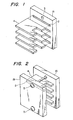
- FIG. 1 A conventional type of arc-suppressing apparatus for a circuit breaker is shown in Figs. 1 and 2.
- reference numerals 1A, 1B denote a pair of side plates 1A, 1B formed from an insulating material, each having a plurality of grooves 2. Grids 4 fit into and are held by the grooves 2.
- a through-hole 3 is formed in each of the side plates 1A, 1B, ' and a bolt 5 extends through the through-hole 3 for clamping the side plates together.
- the grids 4, called de-ionizing grids are formed with a magnetic material.
- the bolt 5 is inserted in the through-hole 3 to clamp the side plates 1A, 1B with the aid of a nut (not illustrated).
- a plurality of grids 4 are arranged at predetermined positions, and the side plates 1A, 1B are fitted thereto.
- the arrangement of the grids 4 at the predetermined positions involves a special tool and considerable trouble.
- an object of the present invention is to provide an arc-suppressing apparatus into which grids can be incorporated without requiring the use of any special tool. This is achieved by an arc-suppressing apparatus according to the appended claims.
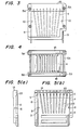
- a pair of side plates 1A, 1B made from a phenolic resin material, have a plurality of first grooves for accomodating and supporting a plurality of de-ionizing grids 4 of width A at predetermined positions. Additional grooves 6, 7 are formed in the side plates 1A, 1B for supporting insulating barriers 9.
- Each of the side plates 1A, 1B has through-holes 3 therein for accommodating bolts 5A and nuts 5B, which secure the side plates together.
- Each of the first grooves 2 has a second groove 22 at an end thereof which is shallower than the first groove.
- Each of the second grooves 22 extends linearly from each of the first grooves 2 to an edge of the side plate 1A or 1B. Spacing struts 10 extend between the side plates 1A, 1B and fit into holes 8 in the side plates 1A, 1B.
- the spacing struts 10 and the-insulating barriers 9 are first fitted into the side plates 1A, 1B so that a space B exists between the side plates 1A, 1B, as shown in Fig. 6.
- the space B is slightly larger than the width A of the grids.
- the bolts 5A and the nuts 5B can be inserted loosely.
- the grids 4 can be fitted in the first grooves 2 by sliding the grids through the second groove 22, as shown in Fig. 7.
- the bolts 5A and the nuts 5B can be tightened, as illustrated in Fig. 4 and Fig. 7 thereby firmly fitting the grids 4 correctly in the first grooves 2.
- the insulating barrier 9 is first fitted together with the spacing strut 10.
- the insulating barrier can-be fitted in a manner similar to that used in fitting the grids 4 by providing a shallow fourth groove like the second groove 22 on one end of the. third grooves 6, 7, as illustrated in Fig. 8.
- the arc-suppressing apparatus Since the grids 4 can be fitted one-by-one during production, as described, the arc-suppressing apparatus according to the present invention is ready for easy assembling without using a special tool therefore.
- the apparatus is, therefore, suitable for production, and the grid can be inserted or removed easily after delivery to customers.
Landscapes
- Arc-Extinguishing Devices That Are Switches (AREA)
- Breakers (AREA)
Applications Claiming Priority (2)
| Application Number | Priority Date | Filing Date | Title |
|---|---|---|---|
| JP1981051064U JPS57161851U (de) | 1981-04-06 | 1981-04-06 | |
| JP51064/81 | 1981-04-06 |
Publications (2)
| Publication Number | Publication Date |
|---|---|
| EP0062350A1 true EP0062350A1 (de) | 1982-10-13 |
| EP0062350B1 EP0062350B1 (de) | 1985-07-31 |
Family
ID=12876362
Family Applications (1)
| Application Number | Title | Priority Date | Filing Date |
|---|---|---|---|
| EP82102945A Expired EP0062350B1 (de) | 1981-04-06 | 1982-04-06 | Lichtbogenschutz für Leistungsschalter |
Country Status (7)
| Country | Link |
|---|---|
| US (1) | US4446347A (de) |
| EP (1) | EP0062350B1 (de) |
| JP (1) | JPS57161851U (de) |
| KR (1) | KR880000764Y1 (de) |
| AU (1) | AU549747B2 (de) |
| DE (1) | DE3265014D1 (de) |
| IN (1) | IN156140B (de) |
Cited By (2)
| Publication number | Priority date | Publication date | Assignee | Title |
|---|---|---|---|---|
| EP0309386A1 (de) * | 1987-09-23 | 1989-03-29 | Siemens Aktiengesellschaft | Mehrpoliger Niederspannungs-Leistungsschalter mit einem Isolierstoffgehäuse und Lichtbogenlöschkammern |
| WO1998012722A1 (de) * | 1996-09-16 | 1998-03-26 | Siemens Aktiengesellschaft | Lichtbogenlöschkammer mit zweiteiligem gehäuse |
Families Citing this family (4)
| Publication number | Priority date | Publication date | Assignee | Title |
|---|---|---|---|---|
| AU563774B2 (en) * | 1985-03-26 | 1987-07-23 | Mitsubishi Denki Kabushiki Kaisha | Arc chute for circuit breaker |
| US4684772A (en) * | 1985-04-09 | 1987-08-04 | Square D Company | Mounting apparatus for arc quenching plates for electric contacts |
| KR19980054544U (ko) * | 1996-12-31 | 1998-10-07 | 이종수 | 배선용 차단기의 소호장치 |
| US8619395B2 (en) | 2010-03-12 | 2013-12-31 | Arc Suppression Technologies, Llc | Two terminal arc suppressor |
Citations (5)
| Publication number | Priority date | Publication date | Assignee | Title |
|---|---|---|---|---|
| US1697143A (en) * | 1927-02-01 | 1929-01-01 | Westinghouse Electric & Mfg Co | Arc chute |
| US2160681A (en) * | 1937-12-30 | 1939-05-30 | Westinghouse Electric & Mfg Co | Circuit interrupter |
| DE1034742B (de) * | 1957-07-19 | 1958-07-24 | Licentia Gmbh | Befestigung von Loeschblechen in einander gegenueberliegenden Nuten der Waende von Lichtbogenloeschkammern |
| US3031552A (en) * | 1959-05-28 | 1962-04-24 | Gen Electric | Electric circuit interrupter |
| FR2179815A1 (en) * | 1972-04-08 | 1973-11-23 | Licentia Gmbh | Power contact breaker boxes - with casings and baffle surfaces of tracking resistant reinforced polyester moulding cpd |
Family Cites Families (3)
| Publication number | Priority date | Publication date | Assignee | Title |
|---|---|---|---|---|
| US1932090A (en) * | 1927-04-29 | 1933-10-24 | Westinghouse Electric & Mfg Co | Circuit breaker |
| US3374332A (en) * | 1965-07-16 | 1968-03-19 | Square D Co | Arc chute for a circuit breaker |
| US3441699A (en) * | 1968-05-27 | 1969-04-29 | Erickson Electrical Equipment | Arc control apparatus for load-break switches |
-
1981
- 1981-04-06 JP JP1981051064U patent/JPS57161851U/ja active Pending
-
1982
- 1982-03-12 KR KR2019820001904U patent/KR880000764Y1/ko not_active Expired
- 1982-04-05 US US06/365,939 patent/US4446347A/en not_active Expired - Lifetime
- 1982-04-06 EP EP82102945A patent/EP0062350B1/de not_active Expired
- 1982-04-06 AU AU82398/82A patent/AU549747B2/en not_active Ceased
- 1982-04-06 DE DE8282102945T patent/DE3265014D1/de not_active Expired
- 1982-04-07 IN IN391/CAL/82A patent/IN156140B/en unknown
Patent Citations (5)
| Publication number | Priority date | Publication date | Assignee | Title |
|---|---|---|---|---|
| US1697143A (en) * | 1927-02-01 | 1929-01-01 | Westinghouse Electric & Mfg Co | Arc chute |
| US2160681A (en) * | 1937-12-30 | 1939-05-30 | Westinghouse Electric & Mfg Co | Circuit interrupter |
| DE1034742B (de) * | 1957-07-19 | 1958-07-24 | Licentia Gmbh | Befestigung von Loeschblechen in einander gegenueberliegenden Nuten der Waende von Lichtbogenloeschkammern |
| US3031552A (en) * | 1959-05-28 | 1962-04-24 | Gen Electric | Electric circuit interrupter |
| FR2179815A1 (en) * | 1972-04-08 | 1973-11-23 | Licentia Gmbh | Power contact breaker boxes - with casings and baffle surfaces of tracking resistant reinforced polyester moulding cpd |
Cited By (3)
| Publication number | Priority date | Publication date | Assignee | Title |
|---|---|---|---|---|
| EP0309386A1 (de) * | 1987-09-23 | 1989-03-29 | Siemens Aktiengesellschaft | Mehrpoliger Niederspannungs-Leistungsschalter mit einem Isolierstoffgehäuse und Lichtbogenlöschkammern |
| US4845460A (en) * | 1987-09-23 | 1989-07-04 | Siemens Aktiengesellschaft | Multipole low-voltage circuit breaker with an insulating material housing and arc-quenching chambers |
| WO1998012722A1 (de) * | 1996-09-16 | 1998-03-26 | Siemens Aktiengesellschaft | Lichtbogenlöschkammer mit zweiteiligem gehäuse |
Also Published As
| Publication number | Publication date |
|---|---|
| AU8239882A (en) | 1982-10-14 |
| JPS57161851U (de) | 1982-10-12 |
| EP0062350B1 (de) | 1985-07-31 |
| IN156140B (de) | 1985-05-18 |
| KR830003365U (ko) | 1983-12-12 |
| KR880000764Y1 (ko) | 1988-03-15 |
| DE3265014D1 (en) | 1985-09-05 |
| AU549747B2 (en) | 1986-02-13 |
| US4446347A (en) | 1984-05-01 |
Similar Documents
| Publication | Publication Date | Title |
|---|---|---|
| DE3888140T2 (de) | Hochkalibriger mehrpoliger Ausschalter mit abgeformtem Gehäuse. | |
| US6435888B1 (en) | Captive splice assembly for electrical bus and method for using same | |
| US3258733A (en) | Wire connector | |
| EP2911253B1 (de) | Sammelschienenadapter und System aus Sammelschienen und einem Sammelschienenadapter | |
| US3995103A (en) | Electrical bussing and jumper assembly | |
| EP0062350B1 (de) | Lichtbogenschutz für Leistungsschalter | |
| EP0170161A2 (de) | Installationsgerät für Sammelschienensysteme | |
| EP1636814B1 (de) | Anschlussmodul für leistungsschalter | |
| EP0634765A1 (de) | Flexible Verbindung für einen Leistungsschalter | |
| US2903671A (en) | Electrical terminal connector block | |
| US3651449A (en) | Resilient terminal blocks | |
| EP0086316A2 (de) | Steckkontaktvorrichtung zur Herstellung einer elektrischen Verbindung zwischen zwei Schienen | |
| DE102019214012A1 (de) | Kontaktbuchse, Leiterplattenanordnung und Stecksystem damit | |
| US6307456B1 (en) | Light industrial circuit breaker terminal cover | |
| US6220806B1 (en) | Twin impression push nut | |
| KR100622743B1 (ko) | 보호 계전기용 터미널 블록 | |
| DE1639232B1 (de) | Elektromagnetisches Relais | |
| US3504221A (en) | Adjustable spark gap structure with preionizing means | |
| EP1232508B1 (de) | Elektrisches schaltgerät mit mehreren gehäuseteilen | |
| DE19534690B4 (de) | Abgangskasten für Schienenverteiler | |
| EP0317586B1 (de) | Codiersystem für steckverbinderzusammenstellungen | |
| US1651360A (en) | Lightning arrester | |
| DE1274715B (de) | Reihentrennklemme, insbesondere trennbarer Reihenloetverbinder | |
| DE1615704C3 (de) | Elektrisches Installationsgerät | |
| ES278106U (es) | Perfeccionamientos en un fusible electrico intercambiable |
Legal Events
| Date | Code | Title | Description |
|---|---|---|---|
| PUAI | Public reference made under article 153(3) epc to a published international application that has entered the european phase |
Free format text: ORIGINAL CODE: 0009012 |
|
| AK | Designated contracting states |
Designated state(s): DE FR GB IT |
|
| 17P | Request for examination filed |
Effective date: 19830113 |
|
| ITF | It: translation for a ep patent filed | ||
| GRAA | (expected) grant |
Free format text: ORIGINAL CODE: 0009210 |
|
| AK | Designated contracting states |
Designated state(s): DE FR GB IT |
|
| REF | Corresponds to: |
Ref document number: 3265014 Country of ref document: DE Date of ref document: 19850905 |
|
| ET | Fr: translation filed | ||
| PLBE | No opposition filed within time limit |
Free format text: ORIGINAL CODE: 0009261 |
|
| STAA | Information on the status of an ep patent application or granted ep patent |
Free format text: STATUS: NO OPPOSITION FILED WITHIN TIME LIMIT |
|
| 26N | No opposition filed | ||
| ITTA | It: last paid annual fee | ||
| PGFP | Annual fee paid to national office [announced via postgrant information from national office to epo] |
Ref country code: GB Payment date: 19920320 Year of fee payment: 11 |
|
| PG25 | Lapsed in a contracting state [announced via postgrant information from national office to epo] |
Ref country code: GB Effective date: 19930406 |
|
| GBPC | Gb: european patent ceased through non-payment of renewal fee |
Effective date: 19930406 |
|
| PGFP | Annual fee paid to national office [announced via postgrant information from national office to epo] |
Ref country code: DE Payment date: 19950410 Year of fee payment: 14 |
|
| PGFP | Annual fee paid to national office [announced via postgrant information from national office to epo] |
Ref country code: FR Payment date: 19950411 Year of fee payment: 14 |
|
| REG | Reference to a national code |
Ref country code: FR Ref legal event code: D6 |
|
| PG25 | Lapsed in a contracting state [announced via postgrant information from national office to epo] |
Ref country code: FR Effective date: 19961227 |
|
| PG25 | Lapsed in a contracting state [announced via postgrant information from national office to epo] |
Ref country code: DE Effective date: 19970101 |
|
| REG | Reference to a national code |
Ref country code: FR Ref legal event code: ST |