EP0062354B1 - "Sealed beam" reflektierende Lampe - Google Patents
"Sealed beam" reflektierende Lampe Download PDFInfo
- Publication number
- EP0062354B1 EP0062354B1 EP82102959A EP82102959A EP0062354B1 EP 0062354 B1 EP0062354 B1 EP 0062354B1 EP 82102959 A EP82102959 A EP 82102959A EP 82102959 A EP82102959 A EP 82102959A EP 0062354 B1 EP0062354 B1 EP 0062354B1
- Authority
- EP
- European Patent Office
- Prior art keywords
- lamp
- front lens
- lens
- ring
- luminous intensity
- Prior art date
- Legal status (The legal status is an assumption and is not a legal conclusion. Google has not performed a legal analysis and makes no representation as to the accuracy of the status listed.)
- Expired
Links
- WFKWXMTUELFFGS-UHFFFAOYSA-N tungsten Chemical compound [W] WFKWXMTUELFFGS-UHFFFAOYSA-N 0.000 claims description 8
- 229910052721 tungsten Inorganic materials 0.000 claims description 8
- 239000010937 tungsten Substances 0.000 claims description 8
- 229910052751 metal Inorganic materials 0.000 claims description 7
- 239000002184 metal Substances 0.000 claims description 7
- 230000001154 acute effect Effects 0.000 claims description 2
- 238000009826 distribution Methods 0.000 description 4
- 230000000694 effects Effects 0.000 description 4
- 229910052782 aluminium Inorganic materials 0.000 description 3
- XAGFODPZIPBFFR-UHFFFAOYSA-N aluminium Chemical compound [Al] XAGFODPZIPBFFR-UHFFFAOYSA-N 0.000 description 3
- XKRFYHLGVUSROY-UHFFFAOYSA-N Argon Chemical compound [Ar] XKRFYHLGVUSROY-UHFFFAOYSA-N 0.000 description 2
- 230000001747 exhibiting effect Effects 0.000 description 2
- 239000011521 glass Substances 0.000 description 2
- 239000004411 aluminium Substances 0.000 description 1
- 229910052786 argon Inorganic materials 0.000 description 1
- 238000005219 brazing Methods 0.000 description 1
- 230000007423 decrease Effects 0.000 description 1
- 230000004313 glare Effects 0.000 description 1
- 230000001771 impaired effect Effects 0.000 description 1
- 239000011261 inert gas Substances 0.000 description 1
- 238000000034 method Methods 0.000 description 1
- 238000000465 moulding Methods 0.000 description 1
- 238000003825 pressing Methods 0.000 description 1
- 239000002994 raw material Substances 0.000 description 1
Images
Classifications
-
- H—ELECTRICITY
- H01—ELECTRIC ELEMENTS
- H01K—ELECTRIC INCANDESCENT LAMPS
- H01K1/00—Details
- H01K1/28—Envelopes; Vessels
- H01K1/30—Envelopes; Vessels incorporating lenses
-
- H—ELECTRICITY
- H01—ELECTRIC ELEMENTS
- H01K—ELECTRIC INCANDESCENT LAMPS
- H01K1/00—Details
- H01K1/28—Envelopes; Vessels
Definitions
- the present invention relates to a sealed beam reflective lamp and, more particularly, to an improvement in a front lens of an envelope of a sealed beam type reflective lamp having reflective lighting characteristics of spot lighting type.
- a sealed beam reflective lamp comprises a reflector on the inner surface of which is deposited a metal reflective film of aluminum or the like, a light source assembly having a tungsten coil filament arranged near the central axis of the reflector, and a front lens sealed to the opening of the reflector.
- Sealed beam reflective lamps are classified into those of spot lighting type and those of flood lighting type according to the size of the illuminating area.
- a sealed beam reflective lamp of spot lighting type a beam spread exhibiting a luminous intensity of half the central luminous intensity is 15°. The deviation of the luminous intensity at the illuminating area is required to be small.
- a lamp of 100 V-100 W is known which has an envelope having a diameter of about 121 mm (1/8"x38).
- the inner surface of the front lens is stippled to disperse incident light.
- a front lens having such stipples has an unsatisfactory converging effect.
- the tungsten coil filament is brought closer to the stippled front lens, the beam spread exhibiting a luminous intensity of half the central luminous intensity exceeds 15°, the central luminous intensity is lowered, and the variation of the luminous intensity in the illuminating area increases.
- a sealed beam reflective lamp having an envelope comprising a front lens and a reflector on the inner surface of which is formed a metal reflective film, and a tungsten coil filament arranged inside said envelope, said front lens consisting of a central circular lens element and a plurality of concentric ring-shaped lens elements, said sealed beam reflective lamp being characterized in that inner surfaces of said ring-shaped lens elements define a stepped inner surface of said front lens, that the acute angles formed by the portion of the central axis of the lamp extending from the front lens towards the inside of the lamp and the generating lines of conical sectors of the ring-shaped lens elements gradually increase toward the center of said front lens from the periphery thereof, that a step difference of said inner surfaces between adjacent ones of said ring-shaped lens elements is not greater than 0.6 mm, and that radial widths of said ring-shaped lens elements increase toward the center of said front lens and are 2 mm or more.
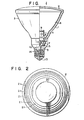
- Fig. 1 is a partially cutaway, sectional view of a sealed beam reflective lamp (100 V-100 W, PAR 38), according to an embodiment of the present invention.
- This lamp has an envelope 3 consisting of a reflector 1 and a front lens 2 covering the opening of the reflector, a light source assembly 4 arranged inside the envelope 3, and a metal base 5 mounted on the end of the envelope 3.
- a metal reflective film 6 of deposited aluminum or the like is formed on the inner surface of the reflector 1.
- a pair of ferrules 7 are mounted on the bottom of the reflector 1.
- the ends of respective lead wires 8 extending through the bottom of the reflector 1 are secured to these ferrules 7 by brazing.
- the other ends of the lead wires 8 are connected to ends of a tungsten coil filament 9.
- the lead wires 8 are supported by a support 10.
- the lead wires 8, the tungsten coil filament 9, and the support 10 constitute the light source assembly 4.
- On the opening end of the reflector 1 is mounted the periphery of the front lens having a plurality of concentric, stepped prism lens elements.
- the interior of the envelope 3 consisting of the reflector 1 and the front lens 2 is evacuated through an evacuating tube 11 formed at the bottom of the envelope 3. Thereafter, an inert gas such as argon is sealed in the envelope 3. The end of the evacuating tube 11 is sealed to provide a sealed end 12.
- the metal base 5 is mounted around the bottom of the envelope 3.
- the metal base 5 consists of an eyelet 13 and a shell 14. Outer wires 15 connected to the ferrules 7 are respectively brazed to the eyelet 13 and the shell 14.
- the eyelet 13 and the shell 14 constitute outer terminals of the lamp.
- Fig. 2 shows the inner surface of the front lens 2.
- the front lens 2 consists of a central circular lens element 20, and a plurality of concentric ring-shaped prism lens elements 21 which surround the lens element 20 and which have stepped inner surfaces.
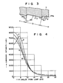
- Fig. 3 is a partial, enlarged, sectional view of the front lens shown in Fig. 2, and shows lens elements 21a, 21 b, and 21c. Angles 81, 82, and so on formed by the inner surfaces of the individual lens elements and the lamp axis gradually increase toward the center of the front lens 2. Since the lens elements 21a, 21b and 21c are farther from the center of the front lens in the order named, ⁇ 2> ⁇ 1. Lines m and n are both lines parallel to the lamp axis. The front lens 2 is divided into a plurality of ring-shaped lens elements by these lines m, n and so on (to be more strict, cylinders of which the traces are lines m, n and so on).
- Radial widths a, b and c of the lens elements 21a, 21b and 21c preferably increase toward the center of the front lens 2.
- An example of the specifications of the front lens having a 123 mm diameter used for the lamp shown in Fig. 1 is shown in Table below:
- the step difference I of the inner surfaces of the adjacent lens elements must be 0.6 mm or less.
- the radial width of each lens element is preferably about 2 mm or more. When the radial width of the lens element is less than 2 mm, the central luminous intensity of the lamp is lowered which is not advantageous.
- the inner surface of the lens element of the present invention may be flat or may have stipples.
- the luminous intensity of the sealed beam reflective lamp of the prior art and of the present invention was measured at various angles from the lamp axis.
- Fig. 4 shows the luminous intensity distribution curves obtained.
- the lamp of the present invention was the lamp shown in Fig. 1 (100 V-100 W, PAR 38) with a front lens having the specifications shown in Table.
- the prior art lamp was substantially the same as that shown in Fig. 1 except that the inner surface of the front lens had only stipples and does not form steps.
- the inner diameter of the effective reflective surface of the reflector was 111.6 mm for each case.
- the luminous intensity was measured at a distance of 3 m from the lamp while rotating the lamp about its axis.
- curves A and B represent the luminous intensity distributions of the lamp of the present invention and the prior art lamp, respectively.
- the central luminous intensity of the prior art lamp is seen to be 7,000 cd (candela)
- the central luminous intensity of the lamp of the present invention (wherein the angles formed by the inner surfaces of the individual lens elements of the front lens and the lamp axis gradually increase toward the center of the front lens) is seen to be 7,630 cd. It is seen from this comparison that the lamp of the present invention is improved over the prior art lamp.
- Curves C and D respectively show luminous intensity distributions when the positions of the tungsten filaments of the lamp of the present invention and the prior art were
- the converging effects are better and the central luminous intensity is higher as those of the prior art lamp which has a front lens the inner surface of which is merely stippled. Further, even when the filament is brought closer to the front lens for the purpose of increasing the central luminous intensity, the light beam does not spread, and the deviation of the luminous intensity at the illuminating area is small.
- the lamp of the present invention is thus capable of excellent spot lighting.
Landscapes
- Non-Portable Lighting Devices Or Systems Thereof (AREA)
- Optical Elements Other Than Lenses (AREA)
Claims (1)
- "Sealed beam" reflektierende Lampe oder -Reflektor-lampe mit einem Kolben (3), umfassendeine Frontlinse (2),einen Reflektor (1), auf dessen Innenfläche eine reflektierende Metallschicht (6) ausgebildet ist, undeine im Kolben (3) angeordnete Wolfram-Glühwendel (9),wobei die Frontlinse (2) aus einem zentralen, kreisförmigen Linsenelement (20) und einer Anzahl von konzentrischen, ringförmigen Linsenelementen (21) besteht,
dadurch gekennzeichnet,daß die Innenflächen der ringförmigen Linsenelemente (21) eine abgestufte Innenfläche der Frontlinse (2) festlegen,daß die spitzen Winkel, die durch den von der Frontlinse (2) zur Innenseite der Lampe verlaufenden Abschnitt der Zentralachse der Lampe und die Erzeugenden von konischen Sektoren der ringförmigen Linsenelemente (21) gebildet werden, sich zum Zentrum der Frontlinse (2) hin von ihrem Umfang her allmählich vergrößern,daß eine Stufendifferenz der Innenflächen zwischen benachbarten der ringförmigen Linsenelemente (21) nicht größer ist als 0,6 mm unddaß radiale Breiten der ringförmigen Linsenelemente (21) sich zum Zentrum der Frontlinse (2) hin vergrößern und 2 mm oder mehr betragen.
Applications Claiming Priority (2)
| Application Number | Priority Date | Filing Date | Title |
|---|---|---|---|
| JP56051058A JPS57165952A (en) | 1981-04-07 | 1981-04-07 | Light emitting sealed beam bulb |
| JP51058/81 | 1981-04-07 |
Publications (3)
| Publication Number | Publication Date |
|---|---|
| EP0062354A2 EP0062354A2 (de) | 1982-10-13 |
| EP0062354A3 EP0062354A3 (en) | 1983-06-08 |
| EP0062354B1 true EP0062354B1 (de) | 1986-12-03 |
Family
ID=12876200
Family Applications (1)
| Application Number | Title | Priority Date | Filing Date |
|---|---|---|---|
| EP82102959A Expired EP0062354B1 (de) | 1981-04-07 | 1982-04-06 | "Sealed beam" reflektierende Lampe |
Country Status (5)
| Country | Link |
|---|---|
| US (1) | US4496872A (de) |
| EP (1) | EP0062354B1 (de) |
| JP (1) | JPS57165952A (de) |
| CA (1) | CA1197495A (de) |
| DE (1) | DE3274599D1 (de) |
Families Citing this family (1)
| Publication number | Priority date | Publication date | Assignee | Title |
|---|---|---|---|---|
| US5493170A (en) * | 1994-09-09 | 1996-02-20 | Philips Electronics North America Corporation | High efficiency sealed beam reflector lamp |
Family Cites Families (10)
| Publication number | Priority date | Publication date | Assignee | Title |
|---|---|---|---|---|
| US2191278A (en) * | 1937-12-13 | 1940-02-20 | Roy W Johnson | Vehicle lamp |
| DE1179164B (de) * | 1952-08-22 | 1964-10-08 | Elastic Stop Nut Corp | Katadioptrische Leuchtenabdeckung |
| US2831394A (en) * | 1952-08-22 | 1958-04-22 | Elastic Stop Nut Corp | Catadioptric lenses |
| US3392277A (en) * | 1966-07-05 | 1968-07-09 | Dietz Co R E | Warning light with reflector |
| US3743385A (en) * | 1970-04-02 | 1973-07-03 | Anchor Hocking Corp | Fresnel aspheric lens |
| US4039885A (en) * | 1975-02-22 | 1977-08-02 | U.S. Philips Corporation | Electric incandescent lamp |
| US4152756A (en) * | 1977-06-27 | 1979-05-01 | General Signal Corporation | Railroad crossing signal lamp |
| US4158222A (en) * | 1977-09-26 | 1979-06-12 | Gulf & Western Industries, Inc. | Limited visibility signal device |
| JPS54147676A (en) * | 1978-05-10 | 1979-11-19 | Toshiba Corp | Lens for sealed beam type bulb and bulb |
| GB2089956B (en) * | 1980-12-22 | 1984-07-04 | Gen Electric | Lamp with shaped reflector and lens |
-
1981
- 1981-04-07 JP JP56051058A patent/JPS57165952A/ja active Pending
-
1982
- 1982-04-05 CA CA000400474A patent/CA1197495A/en not_active Expired
- 1982-04-05 US US06/365,384 patent/US4496872A/en not_active Expired - Fee Related
- 1982-04-06 DE DE8282102959T patent/DE3274599D1/de not_active Expired
- 1982-04-06 EP EP82102959A patent/EP0062354B1/de not_active Expired
Also Published As
| Publication number | Publication date |
|---|---|
| CA1197495A (en) | 1985-12-03 |
| US4496872A (en) | 1985-01-29 |
| EP0062354A3 (en) | 1983-06-08 |
| JPS57165952A (en) | 1982-10-13 |
| EP0062354A2 (de) | 1982-10-13 |
| DE3274599D1 (en) | 1987-01-15 |
Similar Documents
| Publication | Publication Date | Title |
|---|---|---|
| CA2283804C (en) | Vehicle lamps with glare control | |
| US4855886A (en) | Luminaire having a faceted reflecting surface | |
| JPS6252802A (ja) | ランプレフレクタ | |
| CA1067872A (en) | Electric reflector lamp | |
| US2568494A (en) | Vehicle head lamp | |
| US6252338B1 (en) | Reflector lamp having a reflecting section with faceted surfaces | |
| US5199787A (en) | Reflector lamp having improved lens | |
| CA1064089A (en) | Rectangular headlamp filament shield | |
| US4480296A (en) | Two-filament lamp for automobile headlight | |
| CA2624733C (en) | Faceted par lamp | |
| JPH10512095A (ja) | 反射電灯 | |
| EP0062354B1 (de) | "Sealed beam" reflektierende Lampe | |
| US4303965A (en) | Single-mode vehicular headlamp system | |
| US2232816A (en) | Electric lamp | |
| US6281630B1 (en) | Vehicle lamps with glare control | |
| US2782297A (en) | Light projection device | |
| US3979622A (en) | Headlight and incandescent lamp for anti-dazzle beam | |
| US2617062A (en) | Electric incandescent lamp | |
| US4302698A (en) | Dual-filament halogen incandescent lamp, particularly sealed-beam, automotive headlight | |
| US4195245A (en) | Sealed beam lamp for automobile | |
| US3826913A (en) | Distributively banded reflector surface for producing contoured illumination intensity | |
| EP0271857B1 (de) | Kompakte Doppelglühwendel mit Haltern | |
| JPS6118303B2 (de) | ||
| US7332853B2 (en) | Halogen dual-beam lamp | |
| CA1188663A (en) | Signalling light |
Legal Events
| Date | Code | Title | Description |
|---|---|---|---|
| PUAI | Public reference made under article 153(3) epc to a published international application that has entered the european phase |
Free format text: ORIGINAL CODE: 0009012 |
|
| 17P | Request for examination filed |
Effective date: 19820503 |
|
| AK | Designated contracting states |
Designated state(s): CH DE GB IT LI NL |
|
| PUAL | Search report despatched |
Free format text: ORIGINAL CODE: 0009013 |
|
| AK | Designated contracting states |
Designated state(s): CH DE GB IT LI NL |
|
| RAP1 | Party data changed (applicant data changed or rights of an application transferred) |
Owner name: KABUSHIKI KAISHA TOSHIBA |
|
| GRAA | (expected) grant |
Free format text: ORIGINAL CODE: 0009210 |
|
| AK | Designated contracting states |
Kind code of ref document: B1 Designated state(s): CH DE GB IT LI NL |
|
| ITF | It: translation for a ep patent filed | ||
| REF | Corresponds to: |
Ref document number: 3274599 Country of ref document: DE Date of ref document: 19870115 |
|
| PLBE | No opposition filed within time limit |
Free format text: ORIGINAL CODE: 0009261 |
|
| STAA | Information on the status of an ep patent application or granted ep patent |
Free format text: STATUS: NO OPPOSITION FILED WITHIN TIME LIMIT |
|
| 26N | No opposition filed | ||
| PGFP | Annual fee paid to national office [announced via postgrant information from national office to epo] |
Ref country code: GB Payment date: 19910327 Year of fee payment: 10 |
|
| ITTA | It: last paid annual fee | ||
| PGFP | Annual fee paid to national office [announced via postgrant information from national office to epo] |
Ref country code: NL Payment date: 19910430 Year of fee payment: 10 Ref country code: DE Payment date: 19910430 Year of fee payment: 10 |
|
| PGFP | Annual fee paid to national office [announced via postgrant information from national office to epo] |
Ref country code: CH Payment date: 19910507 Year of fee payment: 10 |
|
| PG25 | Lapsed in a contracting state [announced via postgrant information from national office to epo] |
Ref country code: GB Effective date: 19920406 |
|
| PG25 | Lapsed in a contracting state [announced via postgrant information from national office to epo] |
Ref country code: LI Effective date: 19920430 Ref country code: CH Effective date: 19920430 |
|
| PG25 | Lapsed in a contracting state [announced via postgrant information from national office to epo] |
Ref country code: NL Effective date: 19921101 |
|
| GBPC | Gb: european patent ceased through non-payment of renewal fee | ||
| NLV4 | Nl: lapsed or anulled due to non-payment of the annual fee | ||
| REG | Reference to a national code |
Ref country code: CH Ref legal event code: PL |
|
| PG25 | Lapsed in a contracting state [announced via postgrant information from national office to epo] |
Ref country code: DE Effective date: 19930101 |