EP0062356A1 - Vorrichtung zum induktiven Erwärmen, Verfahren zum Erwärmen unter Verwendung eines Wärmeisolators und so erwärmte Werkstücke - Google Patents
Vorrichtung zum induktiven Erwärmen, Verfahren zum Erwärmen unter Verwendung eines Wärmeisolators und so erwärmte Werkstücke Download PDFInfo
- Publication number
- EP0062356A1 EP0062356A1 EP82102987A EP82102987A EP0062356A1 EP 0062356 A1 EP0062356 A1 EP 0062356A1 EP 82102987 A EP82102987 A EP 82102987A EP 82102987 A EP82102987 A EP 82102987A EP 0062356 A1 EP0062356 A1 EP 0062356A1
- Authority
- EP
- European Patent Office
- Prior art keywords
- workpiece
- heat insulating
- heating
- insulating layer
- carbon
- Prior art date
- Legal status (The legal status is an assumption and is not a legal conclusion. Google has not performed a legal analysis and makes no representation as to the accuracy of the status listed.)
- Granted
Links
Images

Classifications
-
- H—ELECTRICITY
- H05—ELECTRIC TECHNIQUES NOT OTHERWISE PROVIDED FOR
- H05B—ELECTRIC HEATING; ELECTRIC LIGHT SOURCES NOT OTHERWISE PROVIDED FOR; CIRCUIT ARRANGEMENTS FOR ELECTRIC LIGHT SOURCES, IN GENERAL
- H05B6/00—Heating by electric, magnetic or electromagnetic fields
- H05B6/02—Induction heating
-
- C—CHEMISTRY; METALLURGY
- C04—CEMENTS; CONCRETE; ARTIFICIAL STONE; CERAMICS; REFRACTORIES
- C04B—LIME, MAGNESIA; SLAG; CEMENTS; COMPOSITIONS THEREOF, e.g. MORTARS, CONCRETE OR LIKE BUILDING MATERIALS; ARTIFICIAL STONE; CERAMICS; REFRACTORIES; TREATMENT OF NATURAL STONE
- C04B35/00—Shaped ceramic products characterised by their composition; Ceramics compositions; Processing powders of inorganic compounds preparatory to the manufacturing of ceramic products
- C04B35/515—Shaped ceramic products characterised by their composition; Ceramics compositions; Processing powders of inorganic compounds preparatory to the manufacturing of ceramic products based on non-oxide ceramics
- C04B35/52—Shaped ceramic products characterised by their composition; Ceramics compositions; Processing powders of inorganic compounds preparatory to the manufacturing of ceramic products based on non-oxide ceramics based on carbon, e.g. graphite
Definitions
- the present invention relates to inductive heating devices and methods for heating workpieces and is suitable for use in graphitizing carbon.
- FIG. 1 A conventional heating device for heating workpieces and, in particular, for graphitizing carbon is shown in Fig. 1 of the accompanying drawings.
- electrodes 2 are placed on opposite sides of pieces of carbon 21.
- a power source 6 supplies electric current to the electrodes 2 and the pieces of carbon 21. The current is passed between the electrodes 2 and, therefore, the current is also passed through the pieces of carbon 21.
- a first thermal insulator 3, comprising carbon powder "A”, is used to fill the spaces between the pieces of carbon 21, the carbon powder "A” facilitating the application of current to the pieces of carbon 21.
- a second thermal insulator 4, comprising carbon powder "B” is used to cover the top of the electrodes 2 and the pieces of carbon 21 to insulate thermally the top of the heating device.
- a refractory member 5 is placed below the electrodes 2, the pieces of carbon 21 and the carbon powder "A” to insulate thermally the bottom of the heating device.
- the first insulator 3 comprising the carbon powder "A"
- the spatial distribution of the current between the electrodes 2 varies, the amount of variation depending on how well the gaps between the pieces of carbon 21 are filled with the carbon powder "A”.
- a long period of time is required for applying current to adequately heat the pieces of carbon 21.
- Such a lengthy current application time results in excessive heat loss through the electrodes 2.
- the ratio: of electric power applied by the power source 6 to the sum of the surface areas of the pieces of carbon 21 to be heated (hereinafter referred to as "a surface power density”) is, in general, set to about 3.5 W/ cm 2 .
- an object of the present invention is to provide a heating device and method which operates more efficiently.
- an inductive heating device for heating a workpiece, characterized by: a heating coil disposed so as to surround said workpiece to be heated; and heat insulating layer means located between said workpiece and said heating coil.
- a method of heating a workpiece characterized in that said workpiece is positioned within an electrical coil, heat insulating layer means is located within the coil between the workpiece and the coil and alternating voltage is supplied to said coil whereby induction heating takes place in said workpiece.
- a workpiece heated by the device or method according to the invention is provided.
- the heat insulating layer reduces the dissipation of heat from the workpiece being heated, and also prevents the surface of the workpiece from oxidizing.
- the heat insulating layer comprises two layers, the first being made of a carbon powder, and the second being made of a carbon and silica powder mixture.
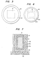
- an inductive heating coil 22 is arranged around a workpiece 21 which is made of carbon.
- the space between the coil 22 and the workpiece 21 is filled with a heat insulating material 23, such as carbon powder "B".
- the coil 22, the workpiece 21 and the heat insulating material 23 are placed on a refractory member 24, made of refractory bricks or the like.
- the heating coil 22 is then connected to an AC power source (not shown).
- the inductive heating coil 22 surrounds the workpiece 21.
- an eddy current is induced in the peripheral portion of the workpiece 21 to be heated.
- the permeation depth of the eddy current varies, depending on the geometry involved and the amount of current flowing in the heating coil 22.
- the core of the workpiece 21 is then heated by the conduction of heat from the peripheral portion of the workpiece.
- the workpiece 21 is surrounded by the heat insulating material 23; such as carbon powder "B".
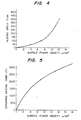
- Heating temperatures and saturated temperatures can be obtained using the above-described heating and insulating method.
- the available heating speed may result in a surface power density of 7.0 W/cm 2 , or more.
- a surface power density of 7.0 W/cm 2 is necessary for maintaining a heating temperature of 2,200° C. With a surface power density in excess of 20 W/cm , the heating speed is extremely high and, therefore, the workpiece may be cracked by thermal shock.
- the heating device and method described above is suitable for manufacturing silicon carbonate.
- the heat insulating material 23 is made of carbon powder, carbon black or charcoal powder. This type of heat insulating material can sufficiently withstand the highest heat treatment temperature (about 3,000° C) which is applied to the workpiece 21.
- the electrical resistance of the heat insulating material 23, which is in contact with the workpiece is considerably decreased; e.g., the heat insulating material 23 becomes electrically conductive.
- a significant eddy current also flows in the heat insulating material 23, thus resulting in a loss of electrical power.
- the workpiece 21 is made of carbon, the temeperature rise is generally limited to 2,900° C per kilogram of the sintered carbon product, with an electric power of 6.0 KWH.
- the workpiece after heat treatment, the workpiece must stand for a length of time sufficient to allow it to cool.
- the workpiece 21 and the heat insulating material 23 have a low thermal conductivity, it takes five to ten days to cool the workpiece to about 400 C, the highest temperature at which the graphitized carbon can be removed from the device without oxidizing in the air.
- Figs. 6 and 7 the heat insulating material 23 has been replaced by two heat insulating layers 23a and 23b.
- the first heat insulating layer 23a is made of carbon powder packed to a thickness of 5 to 15 cm.
- the second heat insulating layer 23b is made of a mixture of carbon powder and silica powder and this layer is dielectric.
- the second heat insulating layer 23b surrounds the first heat insulating layer 23a.
- the first heat insulating layer 23a was made of carbon black and had a thickness of 10 cm.
- the second heat insulating layer 23b 50 parts by weight of petroleum coke, consisting of 25% petroleum coke by weight having a grain size of less than 100 mesh, and 75% petroleum coke by weight having a grain size of 32 to 100 mesh, was uniformly mixed with 50 parts by weight of silica grain having a purity of more than 95% and a grain size of 32 to 100 mesh.
- the resulting mixture had an electrical resistivity of more than 1 ⁇ -cm under a pressure of 1 kg/cm 2 , and was packed into the device to an average thickness of 15 cm to provide the second heat insulating layer 23b.
- the thickness of the first heat insulating layer 23a was 15 cm
- the thickness of the second heat insulating layer 23b was 30 cm.
- the thickness of the first heat insulating layer 23a was 5 cm
- the thickness of the second heat insulating layer 23b was 30 cm.
- the first heat insulating layer 23a was made of a heat insulating material, which was carbon powder having a grain size of less than 32 mesh.
- the other components were exactly the same as those of Example 1.
- a sintered carbon product workpiece was heated in the same manner as in Example .1. In this example, however, the temperature of the workpiece reached 3,000° C with 4 KWH electric power per kilogram of the workpiece, and it took 65 hours to cool the workpiece to 400° C.
- the first heat insulating layer 23a of carbon, and the second heat insulating layer 23b of carbon and silica are provided in such a manner that the layer 23b surrounds the layer 23a. Therefore, the drawbacks accompanying the conventional heating device are eliminated or at least substantially reduced, power consumption is considerably decreased, and the percentage of utilization of the device is increased.
Landscapes
- Engineering & Computer Science (AREA)
- Chemical & Material Sciences (AREA)
- Ceramic Engineering (AREA)
- Physics & Mathematics (AREA)
- Electromagnetism (AREA)
- Manufacturing & Machinery (AREA)
- Materials Engineering (AREA)
- Structural Engineering (AREA)
- Organic Chemistry (AREA)
- General Induction Heating (AREA)
Applications Claiming Priority (2)
| Application Number | Priority Date | Filing Date | Title |
|---|---|---|---|
| JP56053362A JPS57168489A (en) | 1981-04-07 | 1981-04-07 | Stationary induction heater |
| JP53362/81 | 1981-04-07 |
Publications (2)
| Publication Number | Publication Date |
|---|---|
| EP0062356A1 true EP0062356A1 (de) | 1982-10-13 |
| EP0062356B1 EP0062356B1 (de) | 1985-09-11 |
Family
ID=12940690
Family Applications (1)
| Application Number | Title | Priority Date | Filing Date |
|---|---|---|---|
| EP82102987A Expired EP0062356B1 (de) | 1981-04-07 | 1982-04-07 | Vorrichtung zum induktiven Erwärmen, Verfahren zum Erwärmen unter Verwendung eines Wärmeisolators und so erwärmte Werkstücke |
Country Status (4)
| Country | Link |
|---|---|
| US (1) | US4469925A (de) |
| EP (1) | EP0062356B1 (de) |
| JP (1) | JPS57168489A (de) |
| DE (1) | DE3266125D1 (de) |
Families Citing this family (5)
| Publication number | Priority date | Publication date | Assignee | Title |
|---|---|---|---|---|
| FR2568359B1 (fr) * | 1984-07-27 | 1987-01-09 | Siderurgie Fse Inst Rech | Dispositif pour l'homogeneisation en temperature par voie inductive de produits metalliques en defilement |
| DE19652171A1 (de) * | 1996-12-14 | 1998-06-18 | Eric Mix | Verfahren zur thermischen Isolation induktiv geheizter Tiegel und Schmelzen in der Kristallzucht mit kohlenstoffgebundenen Kohlenstofffasern |
| US5947722A (en) * | 1997-07-07 | 1999-09-07 | Iap Research, Inc. | Heat exchanger for particulate material |
| ATE374514T1 (de) * | 2004-04-30 | 2007-10-15 | Sgl Carbon Ag | Werkstückträger für die induktive erwärmung von werkstücken |
| DE102014003126A1 (de) | 2014-03-03 | 2015-09-03 | Clariant International Ltd. | Heizvorrichtung zur Herstellung von Kohlenstofffasern |
Citations (5)
| Publication number | Priority date | Publication date | Assignee | Title |
|---|---|---|---|---|
| US1884600A (en) * | 1931-04-23 | 1932-10-25 | Peter C Reilly | Induction process of graphitizing carbon |
| AT145802B (de) * | 1930-10-28 | 1936-05-25 | Ver Edelstahl Ag | Hartmetall und Verfahren zu dessen Herstellung. |
| GB1071098A (en) * | 1963-10-08 | 1967-06-07 | Siemens Planiawerke Ag | A method and furnace for producing graphite electrodes |
| US3405205A (en) * | 1964-04-13 | 1968-10-08 | Union Carbide Corp | Method of uniformly heating an annular carbonaceous body |
| DE2018764B2 (de) * | 1970-04-18 | 1977-03-24 | Sigri Elektrographit Gmbh, 8901 Meitingen | Hochstromwiderstandsofen zum graphitieren von kohlenstoff |
Family Cites Families (6)
| Publication number | Priority date | Publication date | Assignee | Title |
|---|---|---|---|---|
| US1756457A (en) * | 1926-12-21 | 1930-04-29 | Fourment Marcel | Manufacture of objects consisting of refractory, insulating, abrasive, or like substances |
| US1997741A (en) * | 1933-05-02 | 1935-04-16 | Ajax Electrothermic Corp | Muffle inductor electric furnace |
| US2743306A (en) * | 1953-08-12 | 1956-04-24 | Carborundum Co | Induction furnace |
| JPS576528Y2 (de) * | 1973-08-28 | 1982-02-06 | ||
| JPS54131141A (en) * | 1978-04-04 | 1979-10-12 | Koshuha Netsuren Kk | Induction heating coil and induction heating method |
| JPS605683B2 (ja) * | 1979-08-21 | 1985-02-13 | 東邦レーヨン株式会社 | 黒鉛繊維の製造装置 |
-
1981
- 1981-04-07 JP JP56053362A patent/JPS57168489A/ja active Granted
-
1982
- 1982-04-05 US US06/365,848 patent/US4469925A/en not_active Expired - Lifetime
- 1982-04-07 DE DE8282102987T patent/DE3266125D1/de not_active Expired
- 1982-04-07 EP EP82102987A patent/EP0062356B1/de not_active Expired
Patent Citations (5)
| Publication number | Priority date | Publication date | Assignee | Title |
|---|---|---|---|---|
| AT145802B (de) * | 1930-10-28 | 1936-05-25 | Ver Edelstahl Ag | Hartmetall und Verfahren zu dessen Herstellung. |
| US1884600A (en) * | 1931-04-23 | 1932-10-25 | Peter C Reilly | Induction process of graphitizing carbon |
| GB1071098A (en) * | 1963-10-08 | 1967-06-07 | Siemens Planiawerke Ag | A method and furnace for producing graphite electrodes |
| US3405205A (en) * | 1964-04-13 | 1968-10-08 | Union Carbide Corp | Method of uniformly heating an annular carbonaceous body |
| DE2018764B2 (de) * | 1970-04-18 | 1977-03-24 | Sigri Elektrographit Gmbh, 8901 Meitingen | Hochstromwiderstandsofen zum graphitieren von kohlenstoff |
Also Published As
| Publication number | Publication date |
|---|---|
| JPS57168489A (en) | 1982-10-16 |
| EP0062356B1 (de) | 1985-09-11 |
| DE3266125D1 (en) | 1985-10-17 |
| JPH0232758B2 (de) | 1990-07-23 |
| US4469925A (en) | 1984-09-04 |
Similar Documents
| Publication | Publication Date | Title |
|---|---|---|
| US3461215A (en) | Electric induction furnace | |
| US4104509A (en) | Self-regulating heating element | |
| US5686006A (en) | Induction cooker with coil support having spiral-shaped housing for spiral coil | |
| DE3376810D1 (en) | Autoregulating electric heater | |
| US3332747A (en) | Plural wedge-shaped graphite mold with heating electrodes | |
| JPH01118088A (ja) | 高周波誘導溶融炉 | |
| EP0062356A1 (de) | Vorrichtung zum induktiven Erwärmen, Verfahren zum Erwärmen unter Verwendung eines Wärmeisolators und so erwärmte Werkstücke | |
| JP3881378B2 (ja) | 物品の誘導加熱用電源とその加熱方法 | |
| US3396054A (en) | Method and apparatus for metallic impregnation of carbon and graphite | |
| US702758A (en) | Method of graphitizing electrodes. | |
| JP2515898B2 (ja) | 溶融装置 | |
| US4292505A (en) | Furnace for generating heat by electrical resistance | |
| US3405205A (en) | Method of uniformly heating an annular carbonaceous body | |
| EP1006080B1 (de) | Verfahren zur ständigen verbrennung von kohlepulver | |
| US4503304A (en) | Inductive heating device having a plurality of heating coil units | |
| EP0296562B1 (de) | Giessystem | |
| US2743306A (en) | Induction furnace | |
| JPH0238548B2 (de) | ||
| Brodsky et al. | The low temperature specific heat of NpOs2 and NpRu2 | |
| JP2000281444A (ja) | 円柱状黒鉛材及びその製造方法 | |
| US3624261A (en) | Self-baking electrode structure and method of operating same | |
| US1997622A (en) | Electric furnace and method of operating the same | |
| JPS6237512B2 (de) | ||
| JP2717848B2 (ja) | 焼成炭素電極の黒鉛化方法 | |
| EP1279319A1 (de) | System zur verringerung von temperaturschwankungen während der längenweisen graphitisierung von kohlenstoffkörpern |
Legal Events
| Date | Code | Title | Description |
|---|---|---|---|
| PUAI | Public reference made under article 153(3) epc to a published international application that has entered the european phase |
Free format text: ORIGINAL CODE: 0009012 |
|
| AK | Designated contracting states |
Designated state(s): DE FR GB |
|
| 17P | Request for examination filed |
Effective date: 19830315 |
|
| GRAA | (expected) grant |
Free format text: ORIGINAL CODE: 0009210 |
|
| AK | Designated contracting states |
Designated state(s): DE FR GB |
|
| REF | Corresponds to: |
Ref document number: 3266125 Country of ref document: DE Date of ref document: 19851017 |
|
| ET | Fr: translation filed | ||
| PLBE | No opposition filed within time limit |
Free format text: ORIGINAL CODE: 0009261 |
|
| STAA | Information on the status of an ep patent application or granted ep patent |
Free format text: STATUS: NO OPPOSITION FILED WITHIN TIME LIMIT |
|
| 26N | No opposition filed | ||
| PGFP | Annual fee paid to national office [announced via postgrant information from national office to epo] |
Ref country code: GB Payment date: 19960329 Year of fee payment: 15 |
|
| PGFP | Annual fee paid to national office [announced via postgrant information from national office to epo] |
Ref country code: FR Payment date: 19960410 Year of fee payment: 15 |
|
| PGFP | Annual fee paid to national office [announced via postgrant information from national office to epo] |
Ref country code: DE Payment date: 19960418 Year of fee payment: 15 |
|
| PG25 | Lapsed in a contracting state [announced via postgrant information from national office to epo] |
Ref country code: GB Effective date: 19970407 |
|
| GBPC | Gb: european patent ceased through non-payment of renewal fee |
Effective date: 19970407 |
|
| PG25 | Lapsed in a contracting state [announced via postgrant information from national office to epo] |
Ref country code: FR Free format text: LAPSE BECAUSE OF NON-PAYMENT OF DUE FEES Effective date: 19971231 |
|
| PG25 | Lapsed in a contracting state [announced via postgrant information from national office to epo] |
Ref country code: DE Free format text: LAPSE BECAUSE OF NON-PAYMENT OF DUE FEES Effective date: 19980101 |
|
| REG | Reference to a national code |
Ref country code: FR Ref legal event code: ST |