EP0062359B1 - Levier de commande à ressort - Google Patents
Levier de commande à ressort Download PDFInfo
- Publication number
- EP0062359B1 EP0062359B1 EP82103038A EP82103038A EP0062359B1 EP 0062359 B1 EP0062359 B1 EP 0062359B1 EP 82103038 A EP82103038 A EP 82103038A EP 82103038 A EP82103038 A EP 82103038A EP 0062359 B1 EP0062359 B1 EP 0062359B1
- Authority
- EP
- European Patent Office
- Prior art keywords
- spring
- switch
- torsion spring
- control handle
- grip
- Prior art date
- Legal status (The legal status is an assumption and is not a legal conclusion. Google has not performed a legal analysis and makes no representation as to the accuracy of the status listed.)
- Expired
Links
- 239000004033 plastic Substances 0.000 claims abstract description 8
- 229930182556 Polyacetal Natural products 0.000 claims description 2
- 239000004743 Polypropylene Substances 0.000 claims description 2
- 229920006324 polyoxymethylene Polymers 0.000 claims description 2
- -1 polypropylene Polymers 0.000 claims description 2
- 229920001155 polypropylene Polymers 0.000 claims description 2
- 239000007858 starting material Substances 0.000 description 2
- 229920004943 Delrin® Polymers 0.000 description 1
- 235000003332 Ilex aquifolium Nutrition 0.000 description 1
- 241000209027 Ilex aquifolium Species 0.000 description 1
- 230000015572 biosynthetic process Effects 0.000 description 1
- 238000005352 clarification Methods 0.000 description 1
- 238000010276 construction Methods 0.000 description 1
- 238000010292 electrical insulation Methods 0.000 description 1
Images


Classifications
-
- A—HUMAN NECESSITIES
- A01—AGRICULTURE; FORESTRY; ANIMAL HUSBANDRY; HUNTING; TRAPPING; FISHING
- A01D—HARVESTING; MOWING
- A01D34/00—Mowers; Mowing apparatus of harvesters
- A01D34/01—Mowers; Mowing apparatus of harvesters characterised by features relating to the type of cutting apparatus
- A01D34/412—Mowers; Mowing apparatus of harvesters characterised by features relating to the type of cutting apparatus having rotating cutters
- A01D34/63—Mowers; Mowing apparatus of harvesters characterised by features relating to the type of cutting apparatus having rotating cutters having cutters rotating about a vertical axis
- A01D34/67—Mowers; Mowing apparatus of harvesters characterised by features relating to the type of cutting apparatus having rotating cutters having cutters rotating about a vertical axis hand-guided by a walking operator
- A01D34/68—Mowers; Mowing apparatus of harvesters characterised by features relating to the type of cutting apparatus having rotating cutters having cutters rotating about a vertical axis hand-guided by a walking operator with motor driven cutters or wheels
- A01D34/6806—Driving mechanisms
-
- A—HUMAN NECESSITIES
- A01—AGRICULTURE; FORESTRY; ANIMAL HUSBANDRY; HUNTING; TRAPPING; FISHING
- A01D—HARVESTING; MOWING
- A01D34/00—Mowers; Mowing apparatus of harvesters
- A01D34/01—Mowers; Mowing apparatus of harvesters characterised by features relating to the type of cutting apparatus
- A01D34/412—Mowers; Mowing apparatus of harvesters characterised by features relating to the type of cutting apparatus having rotating cutters
- A01D34/63—Mowers; Mowing apparatus of harvesters characterised by features relating to the type of cutting apparatus having rotating cutters having cutters rotating about a vertical axis
- A01D34/67—Mowers; Mowing apparatus of harvesters characterised by features relating to the type of cutting apparatus having rotating cutters having cutters rotating about a vertical axis hand-guided by a walking operator
- A01D34/68—Mowers; Mowing apparatus of harvesters characterised by features relating to the type of cutting apparatus having rotating cutters having cutters rotating about a vertical axis hand-guided by a walking operator with motor driven cutters or wheels
- A01D2034/6843—Control levers on the handle of the mower
-
- A—HUMAN NECESSITIES
- A01—AGRICULTURE; FORESTRY; ANIMAL HUSBANDRY; HUNTING; TRAPPING; FISHING
- A01D—HARVESTING; MOWING
- A01D2101/00—Lawn-mowers
Definitions
- the invention relates to a spring-loaded switching handle for a lawn mower, which is connected to the switch of an engine via a pull rope and is biased by a spring in the direction of its pivoting position corresponding to the shutdown of the engine.
- a control handle of the aforementioned type is known from US-A No. 4044532.
- the control handle consists of an angle lever which is pivotally mounted on the inside of a spar with its shorter lever end in the plane of the guide bracket for the lawn mower.
- the shorter end of the lever is provided with a cam which actuates an electrical switch on the inside of this spar of the guide bracket when the long leg of the angle lever is pulled against the inside of the horizontal section of the guide bracket.
- the angle lever is biased by a spring in the direction of its inoperative position corresponding to the off-switch position, the two ends of which each rest against the angle lever or against a part which is firmly connected to the guide bracket.
- the angle lever when using the lawnmower, the angle lever must be kept in the on-switching position by the operator while overcoming the force of the spring mentioned.
- the control handle is e.g. designed in such a way that when it is switched on, its shape largely adapts to the shape of the lawn mower handlebar, in which it is gripped by hands when mowing.
- the construction for the known control handle is relatively complex.
- the spring must be shaped according to the axis of rotation and requires abutments on the bar and on the control handle.
- the invention has for its object to provide a spring-loaded shading handle for a lawn mower, which is easier and cheaper to produce than known control handles and still works reliably.
- the invention solves this problem in that the spring is a torsion spring, consists of plastic and at the same time serves as an axis of rotation for the control handle. Surprisingly, it has been shown that the torsion spring is sufficiently elastic without impairing its fatigue strength.
- the design of the control handle and the torsion spring made of plastic also enables the two parts to be formed in one piece.
- a polyacetal is preferred as the plastic because of its better spring properties, e.g. marketed under the Delrin trademark by Du Pont de Nemours.
- a polypropylene is also suitable.
- the formation of the spring-loaded control handle made of plastic also has the advantage that no problems arise because of the required electrical insulation of the switch and the torsion spring.
- a lawn mower 1 is equipped with an electric motor 2. From a (not shown) pull switch on the electric motor 2, a pull cable 3 leads to a U-shaped switching handle 4. This is about an axis, which is coaxial with a torsion spring 5, between the on-switching position shown in FIG. 1 and one to it by about 180 ° offset switch position, which is shown in FIG. 2 with dashed lines, pivotable according to arrow 6.
- the end of the pull cable 3 facing the control handle 4 is attached to a roller 7, which is firmly connected to the torsion spring 5, so that it can be unwound and unwound.
- the torsion spring 5 is designed as a round rod which is flattened at one end 8 to form a square and is fastened to a leg 9 of a spar 10 of the lawn mower with this end.
- the other end 11 of the torsion spring 5 is rotatably mounted in one leg 12 of the spar 10.
- the legs 9, 12 of the spar 10 are cut open in FIG. 2 where the ends 8, 11 of the torsion spring 5 protrude into the spar 10.
- the U-shaped control handle 4 is fixedly connected to its end 13 near the end 11 of the torsion spring 5.
- the other end 14 of the control handle 4 is rotatably mounted near the end 8 of the torsion spring 5 thereon.
- the end 14 of the control handle 4 is thickened and has a bore 15 through which the torsion spring 5 is passed.
- the bore 15 has a somewhat larger diameter than the torsion spring 5, so that at this point the control handle 4 can be easily rotated relative to the torsion spring.
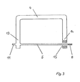
- a switching handle is shown in one piece.
- the end 13 of the control handle 4 in the vicinity of the end 11 of the torsion spring 5 is molded directly onto it.
- the other end 14 of the control handle 4 in the vicinity of the end 8 of the torsion spring 5 is shown in section to illustrate the bore 15.
- the end 8 of the torsion spring 5 is designed as a square.
- the control handle 4 When the lawn mower is not in use, the control handle 4 is in the off-switching position due to the action of the torsion spring 5, which is shown in broken lines in FIG. 2.
- the control handle 4 To switch on the electric motor 2 of the lawnmower, the control handle 4 is pivoted upward by approximately 180 ° into the on-switching position, which can be seen from FIGS. 1 and 2.
- the pull cable 3 is wound around the roller 7 by a corresponding length and actuates the switch of the electric motor 2.
- the on-switch position of the control handle 4 remains only as long as the control handle 4 of the loading servant is held in this position.
- the control handle 4 When the control handle 4 is released, it automatically swings back into the off-switching position due to the action of the torsion spring 5.
- the traction cable is unwound again from the roller 7 by a corresponding length and causes the electric motor 2 to be switched off.
- the lawnmower can also have a petrol engine instead of the electric motor.
- a switch for switching the ignition current on and off is actuated via the spring-loaded switching handle 4 and the pull cable 3, while an additional switch is provided for switching the starter motor on and off.
- the latter additional switch can also be replaced by a timing relay which is switched on simultaneously with the switch for the ignition current when the lawnmower is switched on by the control handle 4 and automatically switches off the starter motor after a predetermined time.
Landscapes
- Life Sciences & Earth Sciences (AREA)
- Environmental Sciences (AREA)
- Harvester Elements (AREA)
Claims (3)
Priority Applications (1)
| Application Number | Priority Date | Filing Date | Title |
|---|---|---|---|
| AT82103038T ATE10895T1 (de) | 1981-04-07 | 1982-04-07 | Gefederter schaltgriff. |
Applications Claiming Priority (2)
| Application Number | Priority Date | Filing Date | Title |
|---|---|---|---|
| DE8110539U | 1981-04-07 | ||
| DE8110539 | 1981-04-07 |
Publications (2)
| Publication Number | Publication Date |
|---|---|
| EP0062359A1 EP0062359A1 (fr) | 1982-10-13 |
| EP0062359B1 true EP0062359B1 (fr) | 1984-12-27 |
Family
ID=6726591
Family Applications (1)
| Application Number | Title | Priority Date | Filing Date |
|---|---|---|---|
| EP82103038A Expired EP0062359B1 (fr) | 1981-04-07 | 1982-04-07 | Levier de commande à ressort |
Country Status (2)
| Country | Link |
|---|---|
| EP (1) | EP0062359B1 (fr) |
| AT (1) | ATE10895T1 (fr) |
Families Citing this family (3)
| Publication number | Priority date | Publication date | Assignee | Title |
|---|---|---|---|---|
| US4573307A (en) * | 1982-09-30 | 1986-03-04 | Outboard Marine Corporation | Lawn mower dead man control |
| US5088273A (en) * | 1990-12-21 | 1992-02-18 | Briggs & Stratton Corporation | Lawnmower handle assembly |
| US5934052A (en) * | 1997-10-29 | 1999-08-10 | Mtd Products Inc. | Lawn mower bail |
Family Cites Families (7)
| Publication number | Priority date | Publication date | Assignee | Title |
|---|---|---|---|---|
| US2352269A (en) * | 1942-01-21 | 1944-06-27 | Jr Frederick Kraissl | Strainer and filter |
| ES197052Y (es) * | 1970-06-19 | 1975-08-16 | Nakata Katsuhide | Barra de torsion perfeccionada. |
| DE2229366A1 (de) * | 1972-06-16 | 1974-01-03 | Licentia Gmbh | Kuehlschrank mit durch federnde klappe verschliessbaren faechern |
| US3955653A (en) * | 1974-04-25 | 1976-05-11 | The Toro Company | Rotary mower blade arrester apparatus |
| DE2529635A1 (de) * | 1975-07-03 | 1977-01-13 | Standard Elektrik Lorenz Ag | Lagervorrichtung fuer eine zweischenkelige torsionsfeder in einem gehaeuse oder einem chassis |
| US4044532A (en) * | 1975-08-25 | 1977-08-30 | The Black And Decker Manufacturing Company | Two-motion switch for cordless lawnmower |
| US4231555A (en) * | 1978-06-12 | 1980-11-04 | Horikiri Spring Manufacturing Co., Ltd. | Bar-shaped torsion spring |
-
1982
- 1982-04-07 EP EP82103038A patent/EP0062359B1/fr not_active Expired
- 1982-04-07 AT AT82103038T patent/ATE10895T1/de active
Also Published As
| Publication number | Publication date |
|---|---|
| ATE10895T1 (de) | 1985-01-15 |
| EP0062359A1 (fr) | 1982-10-13 |
Similar Documents
| Publication | Publication Date | Title |
|---|---|---|
| DE102006013847B4 (de) | Kraftfahrzeugsitz | |
| DE19750116A1 (de) | Verstellmechanismus für die seitlichen Stützbereiche eines Sitzes, insbesondere von dessen Rückenlehne | |
| DE2558985A1 (de) | Feststellvorrichtung an einer schwenkbaren lenkvorrichtung fuer fahrzeuge | |
| DE3929441A1 (de) | Handgefuehrtes arbeitsgeraet | |
| AT397030B (de) | Antriebseinrichtung für bodenbearbeitungswerkzeuge von bodenpflegemaschinen | |
| DE3302544A1 (de) | Elektromaeher mit radantrieb | |
| DE3105951A1 (de) | "kraftwerkzeug" | |
| EP0062359B1 (fr) | Levier de commande à ressort | |
| EP0124117A2 (fr) | Dispositif d'entrée et de centrage pour le raccord à vis | |
| EP2396262B1 (fr) | Chariot pour tuyau | |
| DE2150298C2 (de) | Von Hand und automatisch betätigbare Lenkvorrichtung für Erntemaschinen | |
| DE19652389A1 (de) | Baumschere | |
| DE3029285A1 (de) | Staubsaugermundstueck mit einer buerstenwalze | |
| DE8110539U1 (de) | Gefederter Schaltgriff | |
| EP1327383B1 (fr) | Debroussailleuse | |
| DE2041055C3 (de) | Umschaltvorrichtung zum Verschieben eines Typenhebelträgers einer elektrischen Schreibmaschine | |
| DE3543166C2 (fr) | ||
| DE2623517A1 (de) | Rasenmaeher mit verbrennungskraftmaschine und startvorrichtung | |
| DE646936C (de) | Griffsicherung mit Schalthebel | |
| DE202008002831U1 (de) | Stellhebel zur Höhenverstellung eines Mähwerks | |
| AT206850B (de) | Maschinell angetriebene Wringvorrichtung | |
| EP0532921B1 (fr) | Métier à tricoter rectiligne | |
| DE369874C (de) | Handfessel fuer Gefangene | |
| DE117385C (fr) | ||
| DE627295C (de) | Selbsttaetig wirkende Regel- und UEberwachungsvorrichtung fuer den Ablauf vorbestimmter Betriebsvorgaenge |
Legal Events
| Date | Code | Title | Description |
|---|---|---|---|
| PUAI | Public reference made under article 153(3) epc to a published international application that has entered the european phase |
Free format text: ORIGINAL CODE: 0009012 |
|
| AK | Designated contracting states |
Designated state(s): AT BE CH FR LU NL |
|
| 17P | Request for examination filed |
Effective date: 19821126 |
|
| GRAA | (expected) grant |
Free format text: ORIGINAL CODE: 0009210 |
|
| AK | Designated contracting states |
Designated state(s): AT BE CH FR LI LU NL |
|
| REF | Corresponds to: |
Ref document number: 10895 Country of ref document: AT Date of ref document: 19850115 Kind code of ref document: T |
|
| ET | Fr: translation filed | ||
| PLBE | No opposition filed within time limit |
Free format text: ORIGINAL CODE: 0009261 |
|
| STAA | Information on the status of an ep patent application or granted ep patent |
Free format text: STATUS: NO OPPOSITION FILED WITHIN TIME LIMIT |
|
| 26N | No opposition filed | ||
| PGFP | Annual fee paid to national office [announced via postgrant information from national office to epo] |
Ref country code: CH Payment date: 19920320 Year of fee payment: 11 |
|
| PGFP | Annual fee paid to national office [announced via postgrant information from national office to epo] |
Ref country code: LU Payment date: 19920324 Year of fee payment: 11 |
|
| PGFP | Annual fee paid to national office [announced via postgrant information from national office to epo] |
Ref country code: FR Payment date: 19920326 Year of fee payment: 11 |
|
| PGFP | Annual fee paid to national office [announced via postgrant information from national office to epo] |
Ref country code: AT Payment date: 19920327 Year of fee payment: 11 |
|
| PGFP | Annual fee paid to national office [announced via postgrant information from national office to epo] |
Ref country code: BE Payment date: 19920401 Year of fee payment: 11 |
|
| PGFP | Annual fee paid to national office [announced via postgrant information from national office to epo] |
Ref country code: NL Payment date: 19920430 Year of fee payment: 11 |
|
| EPTA | Lu: last paid annual fee | ||
| PG25 | Lapsed in a contracting state [announced via postgrant information from national office to epo] |
Ref country code: LU Free format text: LAPSE BECAUSE OF NON-PAYMENT OF DUE FEES Effective date: 19930407 Ref country code: AT Effective date: 19930407 |
|
| PG25 | Lapsed in a contracting state [announced via postgrant information from national office to epo] |
Ref country code: LI Effective date: 19930430 Ref country code: CH Effective date: 19930430 Ref country code: BE Effective date: 19930430 |
|
| BERE | Be: lapsed |
Owner name: SABO MASCHINENFABRIK G.M.B.H. & CO K.G. Effective date: 19930430 |
|
| PG25 | Lapsed in a contracting state [announced via postgrant information from national office to epo] |
Ref country code: NL Effective date: 19931101 |
|
| NLV4 | Nl: lapsed or anulled due to non-payment of the annual fee | ||
| PG25 | Lapsed in a contracting state [announced via postgrant information from national office to epo] |
Ref country code: FR Effective date: 19931229 |
|
| REG | Reference to a national code |
Ref country code: CH Ref legal event code: PL |
|
| REG | Reference to a national code |
Ref country code: FR Ref legal event code: ST |