EP0062390B1 - Transducteur pour balayer un objet par ultrasons - Google Patents
Transducteur pour balayer un objet par ultrasons Download PDFInfo
- Publication number
- EP0062390B1 EP0062390B1 EP82200433A EP82200433A EP0062390B1 EP 0062390 B1 EP0062390 B1 EP 0062390B1 EP 82200433 A EP82200433 A EP 82200433A EP 82200433 A EP82200433 A EP 82200433A EP 0062390 B1 EP0062390 B1 EP 0062390B1
- Authority
- EP
- European Patent Office
- Prior art keywords
- reflector
- scanning
- ultrasonic waves
- housing
- scanner
- Prior art date
- Legal status (The legal status is an assumption and is not a legal conclusion. Google has not performed a legal analysis and makes no representation as to the accuracy of the status listed.)
- Expired
Links
- 230000005855 radiation Effects 0.000 title abstract description 6
- 230000005540 biological transmission Effects 0.000 claims description 16
- 230000033001 locomotion Effects 0.000 claims description 9
- 239000011343 solid material Substances 0.000 claims description 3
- 230000000644 propagated effect Effects 0.000 claims description 2
- 230000004044 response Effects 0.000 claims description 2
- 239000007788 liquid Substances 0.000 description 5
- 230000003071 parasitic effect Effects 0.000 description 3
- 230000001902 propagating effect Effects 0.000 description 3
- 230000008901 benefit Effects 0.000 description 2
- 238000010276 construction Methods 0.000 description 2
- 230000003247 decreasing effect Effects 0.000 description 2
- 238000006073 displacement reaction Methods 0.000 description 2
- 238000000034 method Methods 0.000 description 2
- 230000009471 action Effects 0.000 description 1
- 230000015556 catabolic process Effects 0.000 description 1
- 239000003795 chemical substances by application Substances 0.000 description 1
- 238000004891 communication Methods 0.000 description 1
- 239000002131 composite material Substances 0.000 description 1
- 230000008878 coupling Effects 0.000 description 1
- 238000010168 coupling process Methods 0.000 description 1
- 238000005859 coupling reaction Methods 0.000 description 1
- 238000006731 degradation reaction Methods 0.000 description 1
- 230000000593 degrading effect Effects 0.000 description 1
- 238000013461 design Methods 0.000 description 1
- 230000000694 effects Effects 0.000 description 1
- 230000002349 favourable effect Effects 0.000 description 1
- 230000002452 interceptive effect Effects 0.000 description 1
- 239000000463 material Substances 0.000 description 1
- 230000007246 mechanism Effects 0.000 description 1
- 238000012545 processing Methods 0.000 description 1
- 230000035945 sensitivity Effects 0.000 description 1
- 230000003068 static effect Effects 0.000 description 1
- 238000012360 testing method Methods 0.000 description 1
- 230000002463 transducing effect Effects 0.000 description 1
- 239000011800 void material Substances 0.000 description 1
- XLYOFNOQVPJJNP-UHFFFAOYSA-N water Substances O XLYOFNOQVPJJNP-UHFFFAOYSA-N 0.000 description 1
Images
Classifications
-
- G—PHYSICS
- G10—MUSICAL INSTRUMENTS; ACOUSTICS
- G10K—SOUND-PRODUCING DEVICES; METHODS OR DEVICES FOR PROTECTING AGAINST, OR FOR DAMPING, NOISE OR OTHER ACOUSTIC WAVES IN GENERAL; ACOUSTICS NOT OTHERWISE PROVIDED FOR
- G10K11/00—Methods or devices for transmitting, conducting or directing sound in general; Methods or devices for protecting against, or for damping, noise or other acoustic waves in general
- G10K11/18—Methods or devices for transmitting, conducting or directing sound
- G10K11/26—Sound-focusing or directing, e.g. scanning
-
- G—PHYSICS
- G01—MEASURING; TESTING
- G01N—INVESTIGATING OR ANALYSING MATERIALS BY DETERMINING THEIR CHEMICAL OR PHYSICAL PROPERTIES
- G01N29/00—Investigating or analysing materials by the use of ultrasonic, sonic or infrasonic waves; Visualisation of the interior of objects by transmitting ultrasonic or sonic waves through the object
- G01N29/22—Details, e.g. general constructional or apparatus details
- G01N29/221—Arrangements for directing or focusing the acoustical waves
-
- G—PHYSICS
- G10—MUSICAL INSTRUMENTS; ACOUSTICS
- G10K—SOUND-PRODUCING DEVICES; METHODS OR DEVICES FOR PROTECTING AGAINST, OR FOR DAMPING, NOISE OR OTHER ACOUSTIC WAVES IN GENERAL; ACOUSTICS NOT OTHERWISE PROVIDED FOR
- G10K11/00—Methods or devices for transmitting, conducting or directing sound in general; Methods or devices for protecting against, or for damping, noise or other acoustic waves in general
- G10K11/18—Methods or devices for transmitting, conducting or directing sound
- G10K11/26—Sound-focusing or directing, e.g. scanning
- G10K11/28—Sound-focusing or directing, e.g. scanning using reflection, e.g. parabolic reflectors
Definitions
- the invention relates to a scanner for scanning an object by means of ultrasonic radiation.
- a scanner is commonly used for producing by means of pulse-echo techniques a two-dimensional image of a cross-sectional. plane of an object to be examined.
- successive ultrasonic pulses are transmitted in the form of relatively narrow beams to the object under examination in accordance with such a pattern that a sufficiently detailed image of the relevant cross-section of the object can be formed from the different echo signals which are received.
- Techniques known per se can be used for recording, processing and/ or reproducing the reflected and received echo signals.
- a scanner for scanning an object by means of ultrasonic waves comprises a housing defining a space containing a transmission medium for ultrasonic waves, in which housing are disposed: transducer means for transmitting and receiving ultrasonic waves; a plurality of reflectors including one or more movable reflectors mounted for movement relative to the housing and functioning as a scanning reflector, and an object reflector positioned to receive outgoing ultrasonic waves from said scanning reflector; and focussing means for focussing said ultrasonic waves, so arranged that a beam of ultrasonic waves focussed by said focussing means and reflected by said object reflector to the object performs a scanning motion in response to movement of said scanning reflector.
- a scanner of this type is known from US-A--4,185,501.
- This patent discloses a scanner of the sector scan type.
- a disc rotatable about a shaft and having a plurality of lens/reflector combinations peripherally mounted thereon is rotated about this shaft so that these combinations move past a fixedly mounted transducer.
- Ultrasonic radiation emitted from this transducer can be bundled by such a lens/reflector combination when the latter is adjacent the transducer-and reflected to an object reflector fixedly mounted in the housing, which object reflector is a flat surface.
- a succession of mutually parallel beams of ultrasonic radiation is formed by the lens of a respective lens/reflector combination during the latter's movement past the transducer, each of such beams being directed by the reflector of the respective lens/reflector combination from a point on this reflector as determined by the instantaneous angular position of the disc to the fixedly mounted object reflector.
- the resultant arrangement is relatively large and heavy.
- this device permits only limited tilting movement relative to the object to be examined. More- oever, a rotation of the device relative to the object will produce a gyroscopic effect additionally impeding the handling thereof.
- the prior art arrangement cannot be simply modified so that a linear scan instead of a sector scan is achieved.
- a scanner of the above type, except for the afore-said focussing means, is known from DE-U-1,860,245, which discloses a scanner of the type described above.
- the ultrasonic beam originating from fixedly mounted transducer means is so moved via a reflector, which reflector is mounted at an angle relative to the focal line of a fixed parabolically curved, cylindrical object reflector and is adapted to rotate about this focal line, that a so-called linear scan is produced.
- a drawback of this prior art device is that the ultrasonic beam reflected by the object will be incident on at least one point of the object reflector at an approximately right angle. As a result, special steps will have to be taken in order to prevent parasitic, non-geometric reflections.
- a scanner in which an effort is made to reduce such reflection is disclosed in NL-A-80,00299, corresponding to US-A-4,208,602.
- This reference discloses a device in which the beam movement required for scanning the object is achieved by using a swivelling reflector, whereby a sector shaped scan is produced. The occurrence of parasitic, non-geometric reflections in this device is prevented by a specific choice of the material and structure of the scanning reflector.
- the scanners described above have the drawback that, in general, it is relatively difficult to alter the device so as to optimally conform to special requirements set by a user. Special reference is made in this respect to the optimum choice of the ultrasonic frequency band of the transducer means used and the manner of scanning. This is of particular importance for specialist applications, when only a small series of each version will be manufactured.
- the image formed of the desired object area is of an outstanding quality, while being void of interferences caused for example by parasitic, non-geometric reflections, and
- a scanner is characterized in that said focussing means include first focussing means adapted to form a first focus located in the vicinity of said scanning reflector and within the space defined by said housing, and second focussing means adapted to project said first focus into the object; and the sine of the angle at which said ultrasonic waves impinge on the respective ones of said reflective surfaces exceeds the ratio of the propagation velocity of the ultrasonic waves in the respective transmission medium to the propagation velocity of the transversal ultrasonic wave in the respective solid material of said reflective surfaces.
- a scanner for achieving the above object is, according to an embodiment of the invention, further characterized in that said first focussing means are adjustable so that the location of said first focus can be shifted along the main axis of the transmission path between said transducer means and said object reflector.
- a further embodiment of a scanner of the subject invention is characterized thereby that said object reflector is so formed that the ultrasonic beam reflected thereby is focussed in two mutually perpendicular planes.
- an object reflector having the desired characteristics can be readily mounted in the scanner structure. Moreover the position of the object reflector, in particular the focal line thereof, relative to the rotatably mounted scanning reflector, can be optimally adjusted. The scanner can thus be made to operate in accordance with one of the selected scanning modes.
- a preferred embodiment of a scanner according to the invention is further characterized in that said scanning reflector is a body defining a plurality of reflector surfaces, the area of each of said reflector surfaces being small in comparison with the area of the active surface of the transducer means and the absolute aperture of each of said reflector surfaces being reduced relative to the absolute aperture of the transducer means in accordance with a ratio determined by the location of the first focus.
- a preferred embodiment therof is characterized thereby that the reflective surfaces of said scanning reflector are substantially parallel to the direction at which ultrasonic waves are propagated towards orfrom said transducing means.
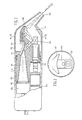
- the drawings show a frame FM, to which frame all of the other components are attached either directly or indirectly.
- This frame is enclosed by a housing adapted to contain a transmission medium for ultrasonic vibrations, which housing includes a rear section AG and a front section VG.
- the front section may be sealed in liquid-tight fashion by means of a window VR that is transparent to ultrasonic waves.
- An acoustic channel AK is provided in the frame, which channel functions as a transmission path for the ultrasonic waves.
- This channel has its one end terminated by a transceiver unit ZO for transmitting and receiving ultrasonic waves, which transceiver unit can be simply replaced by a similar unit having a different rate of vibration.
- the acoustic channel has its other end in open communication with the chamber VL defined by the front section VG.
- Chamber VL houses a rotatable scanning reflector TR having a plurality of mutually identical reflector surfaces and a stationary object OR detachably secured to the frame. The latter arrangement permits the object reflector to be simply replaced by one having different characteristics.
- the transceiver unit is a cylindrically body comprising a cylindrical transducer and a focussing lens FL disposed against the head face thereof, by means of which lens ultrasonic waves produced by the transceiver unit are united into a conical beam that is focussed to an intermediate or first focus TF.
- the shape of the portion of the acoustic channel AK between the focussing lens FL and a stationary reflector RF is adapted to the shape of the beam.
- the location of the first focus while remaining in the vicinity of the scanning relfector TR can be optionally varied.
- the location of this first focus can be varied either statically or dynamically.
- the composite scanning reflector TR comprises four identical, rectangular, flat surfaces mounted normal to one another and spaced identical distances from the axis of rotation.
- the scanning reflector By the choice of the curvature of the reflective surface of the object reflector OR in planes normal to the plane of the drawing of Fig. 1 and by the positioning of the scanning reflector relative to this object reflector (see also Fig. 2), it can be accomplished that a beam received by the object reflector from the scanning reflector during the rotation of the latter relative to the former is reflected so that a sequence of mutually parallel beams is transmitted towards the window VR.
- the device is thus operative as a linear scanner.
- the scanner can be adapted for operation as, for example, a sector scanner or a scanner scanning in accordance with a trapezoidal pattern.
- the curvature of the object reflector in the plane of the drawing of Fig. 2 further results in a focussing of a divergent beam received from the scanning reflector.
- the object reflector is also curved in planes normal to the plane of the drawing of Fig. 1.
- the scanning reflector TR which is bearing mounted in liquid-tight fashion, can be rotated through a coupling, a transmission mechanism and an electric motor EM.
- a synchronizing disc SS is mounted on the shaft for providing signals to be used for speed control and synchronization purposes.
- the acoustic channel AK and the chamber VL are filled with a liquid capable of transmitting ultrasonic energy, for example water.
- the geometry of the transmission path for ultrasonic waves between the transceiver unit ZO and the exit of the chamber VL is such that ultrasonic vibrations propagating in the liquid can strike a portion of the boundary of this transmission path only at such an angle that total reflection occurs at the respective junction of liquid and transmission path boundary.
- Such total reflection will occur if the sine of the angle at which the ultrasonic vibrations propagating in the liquid strike the respective portion of the transmission path boundary is greater than the ratio of the propagation velocity of ultrasonic vibrations in the liquid and the velocity at which the transversal ultrasonic waves propagate in the solid material of this portion of the transmission path boundary.
- this area of optimum depth of field may be shifted in the axial direction of the beam by varying the adjustment of the focussing lens FL and/or the position of the transceiver unit ZO.
Landscapes
- Physics & Mathematics (AREA)
- Acoustics & Sound (AREA)
- Engineering & Computer Science (AREA)
- Multimedia (AREA)
- Biochemistry (AREA)
- Immunology (AREA)
- Chemical & Material Sciences (AREA)
- Analytical Chemistry (AREA)
- Health & Medical Sciences (AREA)
- General Health & Medical Sciences (AREA)
- General Physics & Mathematics (AREA)
- Life Sciences & Earth Sciences (AREA)
- Pathology (AREA)
- Investigating Or Analyzing Materials By The Use Of Ultrasonic Waves (AREA)
- Ultra Sonic Daignosis Equipment (AREA)
- Measurement Of Velocity Or Position Using Acoustic Or Ultrasonic Waves (AREA)
- Surgical Instruments (AREA)
- Length Measuring Devices Characterised By Use Of Acoustic Means (AREA)
Claims (8)
Priority Applications (1)
| Application Number | Priority Date | Filing Date | Title |
|---|---|---|---|
| AT82200433T ATE18101T1 (de) | 1981-04-08 | 1982-04-07 | Wandler zur ultraschallabtastung von objekten. |
Applications Claiming Priority (2)
| Application Number | Priority Date | Filing Date | Title |
|---|---|---|---|
| NL8101744A NL8101744A (nl) | 1981-04-08 | 1981-04-08 | Aftastinrichting voor het met behulp van ultrageluidsstraling aftasten van een objekt. |
| NL8101744 | 1981-04-08 |
Publications (2)
| Publication Number | Publication Date |
|---|---|
| EP0062390A1 EP0062390A1 (fr) | 1982-10-13 |
| EP0062390B1 true EP0062390B1 (fr) | 1986-02-19 |
Family
ID=19837325
Family Applications (1)
| Application Number | Title | Priority Date | Filing Date |
|---|---|---|---|
| EP82200433A Expired EP0062390B1 (fr) | 1981-04-08 | 1982-04-07 | Transducteur pour balayer un objet par ultrasons |
Country Status (10)
| Country | Link |
|---|---|
| US (1) | US4466286A (fr) |
| EP (1) | EP0062390B1 (fr) |
| JP (1) | JPS57179658A (fr) |
| AT (1) | ATE18101T1 (fr) |
| AU (1) | AU550335B2 (fr) |
| CA (1) | CA1173146A (fr) |
| DE (1) | DE3269124D1 (fr) |
| DK (1) | DK163682A (fr) |
| IE (1) | IE52333B1 (fr) |
| NL (1) | NL8101744A (fr) |
Families Citing this family (23)
| Publication number | Priority date | Publication date | Assignee | Title |
|---|---|---|---|---|
| US4508122A (en) * | 1982-11-22 | 1985-04-02 | Ultramed, Inc. | Ultrasonic scanning apparatus and techniques |
| FR2565094B1 (fr) * | 1984-06-01 | 1988-07-15 | Synthelabo | Sonde d'echographie a miroir oscillant de focalisation |
| DE3506249A1 (de) * | 1985-02-22 | 1986-08-28 | Messerschmitt-Bölkow-Blohm GmbH, 8012 Ottobrunn | Verfahren und vorrichtung zur zertruemmerung eines festen koerpers |
| US4807476A (en) * | 1986-12-22 | 1989-02-28 | The Boeing Company | Variable angle transducer system and apparatus for pulse echo inspection of laminated parts through a full radial arc |
| US4935884A (en) * | 1988-04-28 | 1990-06-19 | Champlin Electronics, Inc. | Sonic pipe length detector |
| US5207976A (en) * | 1991-04-05 | 1993-05-04 | Westinghouse Electric Corp. | Pellet slide and inspection assembly in a nuclear fuel pellet surface defect inspection apparatus |
| GB9215231D0 (en) * | 1992-07-17 | 1992-09-02 | Skidmore Robert | Flowmeters |
| US6167760B1 (en) * | 1993-07-01 | 2001-01-02 | The Boeing Company | Ultrasonic inspection system for laminated stiffeners |
| US6568270B2 (en) * | 2001-03-13 | 2003-05-27 | Rosemount Aerospace Inc. | Ultrasonic sensor self test for integrity/performance verification |
| US6993971B2 (en) * | 2003-12-12 | 2006-02-07 | The Boeing Company | Ultrasonic inspection device for inspecting components at preset angles |
| US7484413B2 (en) * | 2003-12-12 | 2009-02-03 | The Boeing Company | Remote radius inspection tool for composite joints |
| DE102004043180B3 (de) * | 2004-09-01 | 2006-05-24 | Fraunhofer-Gesellschaft zur Förderung der angewandten Forschung e.V. | Vorrichtung zur zerstörungsfreien Prüfung von Bauteilen mittels Ultraschallwellen |
| US7315609B2 (en) * | 2004-09-16 | 2008-01-01 | The Boeing Company | Real-time X-ray scanner and remote crawler apparatus and method |
| US7050535B2 (en) | 2004-09-16 | 2006-05-23 | The Boeing Company | X-ray laminography inspection system and method |
| US7617732B2 (en) * | 2005-08-26 | 2009-11-17 | The Boeing Company | Integrated curved linear ultrasonic transducer inspection apparatus, systems, and methods |
| US7640810B2 (en) * | 2005-07-11 | 2010-01-05 | The Boeing Company | Ultrasonic inspection apparatus, system, and method |
| US7444876B2 (en) * | 2005-08-26 | 2008-11-04 | The Boeing Company | Rapid prototype integrated linear ultrasonic transducer inspection apparatus, systems, and methods |
| US7464596B2 (en) * | 2004-09-24 | 2008-12-16 | The Boeing Company | Integrated ultrasonic inspection probes, systems, and methods for inspection of composite assemblies |
| US7249512B2 (en) * | 2005-01-24 | 2007-07-31 | The Boeing Company | Non-destructive stringer inspection apparatus and method |
| US7313959B2 (en) * | 2005-05-25 | 2008-01-01 | The Boeing Company | Magnetically attracted apparatus, system, and method for remote bondline thickness measurement |
| JP2013545976A (ja) * | 2010-10-25 | 2013-12-26 | 株式会社ニコン | 装置、光学アセンブリ、物体を検査又は測定する方法、及び構造体を製造する方法 |
| CN108543690B (zh) * | 2018-03-15 | 2020-04-14 | 陕西师范大学 | 一种基于流体介质的漏斗状超声波约束装置 |
| ES2804059B2 (es) | 2019-07-30 | 2021-08-13 | San Jorge Tecnologicas Sl | Sistema y método para la detección de objetos ocultos bajo la ropa de una persona |
Family Cites Families (6)
| Publication number | Priority date | Publication date | Assignee | Title |
|---|---|---|---|---|
| DE1118396B (de) * | 1959-06-09 | 1961-11-30 | Transform Roentgen Matern Veb | Einrichtung fuer die Ultraschalldiagnostik |
| US3245251A (en) * | 1962-03-02 | 1966-04-12 | Transformatoren & Roentgenwerk | Ultrasonic diagnostic testing apparatus |
| US3529465A (en) * | 1968-02-23 | 1970-09-22 | Claus Kleesattel | Fatigue testing and apparatus therefor |
| US4185501A (en) * | 1978-02-13 | 1980-01-29 | Second Foundation | Ultrasonic sector scanner |
| FI62950C (fi) * | 1978-03-27 | 1983-04-11 | New York Inst Techn | Undersoekningsmodul till en ultraljudsavbildningsanordning |
| US4194510A (en) * | 1978-06-15 | 1980-03-25 | Second Foundation, Inc. | Ultrasonic focusing system |
-
1981
- 1981-04-08 NL NL8101744A patent/NL8101744A/nl not_active Application Discontinuation
-
1982
- 1982-03-16 CA CA000398402A patent/CA1173146A/fr not_active Expired
- 1982-03-18 AU AU81664/82A patent/AU550335B2/en not_active Ceased
- 1982-03-31 US US06/363,908 patent/US4466286A/en not_active Expired - Fee Related
- 1982-04-02 IE IE782/82A patent/IE52333B1/en unknown
- 1982-04-07 DE DE8282200433T patent/DE3269124D1/de not_active Expired
- 1982-04-07 EP EP82200433A patent/EP0062390B1/fr not_active Expired
- 1982-04-07 AT AT82200433T patent/ATE18101T1/de not_active IP Right Cessation
- 1982-04-08 JP JP57057458A patent/JPS57179658A/ja active Pending
- 1982-04-13 DK DK163682A patent/DK163682A/da not_active IP Right Cessation
Also Published As
| Publication number | Publication date |
|---|---|
| NL8101744A (nl) | 1982-11-01 |
| IE52333B1 (en) | 1987-09-16 |
| AU8166482A (en) | 1982-10-14 |
| CA1173146A (fr) | 1984-08-21 |
| AU550335B2 (en) | 1986-03-20 |
| DK163682A (da) | 1982-10-09 |
| EP0062390A1 (fr) | 1982-10-13 |
| JPS57179658A (en) | 1982-11-05 |
| DE3269124D1 (en) | 1986-03-27 |
| ATE18101T1 (de) | 1986-03-15 |
| US4466286A (en) | 1984-08-21 |
| IE820782L (en) | 1982-10-08 |
Similar Documents
| Publication | Publication Date | Title |
|---|---|---|
| EP0062390B1 (fr) | Transducteur pour balayer un objet par ultrasons | |
| EP0432771B1 (fr) | Dispositif à balayage tri-dimensionnel par ultrasons | |
| US4325381A (en) | Ultrasonic scanning head with reduced geometrical distortion | |
| US4213344A (en) | Method and apparatus for providing dynamic focussing and beam steering in an ultrasonic apparatus | |
| EP0110593B1 (fr) | Procédé et dispositif de balayage ultrasonique | |
| US3974475A (en) | Method of and apparatus for focusing ultrasonic waves in a focal line | |
| US4245511A (en) | Ultrasonic applicator for ultrasonic scanning of bodies and method of using the same | |
| US7804056B2 (en) | Energy signal processing system | |
| US4541434A (en) | Ultrasonic scanning apparatus | |
| CN109031242B (zh) | 应用于三维扫描光纤激光雷达的收发一体式远心光学系统 | |
| US3895339A (en) | Acoustic camera apparatus | |
| US4844198A (en) | Plane wave focusing lens | |
| US5616892A (en) | Virtual imaging multiple transducer system | |
| GB1127238A (en) | Improvements in and relating to ultrasonic scanning cell | |
| GB2099997A (en) | Apparatus for ultrasonic imaging | |
| AU750458B2 (en) | Ultrasonic transducer | |
| USRE32062E (en) | Multiple field acoustic focusser | |
| US4035839A (en) | Ultrasonic imaging | |
| US4450542A (en) | Multiple beam lens transducer for sonar systems | |
| GB1591685A (en) | Method and apparatus for non-destructive and non-invasive testing | |
| CN109884722B (zh) | 一种毫米波安检成像装置 | |
| EP0047070A1 (fr) | Tête de balayage par secteur pour un système de formation d'images ultrasonores | |
| JPH034933Y2 (fr) | ||
| JPS56155916A (en) | Photoscanner | |
| NO161710B (no) | Multistraale linse-transduser med kollimator for sonarsystemer. |
Legal Events
| Date | Code | Title | Description |
|---|---|---|---|
| PUAI | Public reference made under article 153(3) epc to a published international application that has entered the european phase |
Free format text: ORIGINAL CODE: 0009012 |
|
| AK | Designated contracting states |
Designated state(s): AT BE CH DE FR GB IT SE |
|
| 17P | Request for examination filed |
Effective date: 19830330 |
|
| GRAA | (expected) grant |
Free format text: ORIGINAL CODE: 0009210 |
|
| AK | Designated contracting states |
Designated state(s): AT BE CH DE FR GB IT LI SE |
|
| REF | Corresponds to: |
Ref document number: 18101 Country of ref document: AT Date of ref document: 19860315 Kind code of ref document: T |
|
| ITF | It: translation for a ep patent filed | ||
| REF | Corresponds to: |
Ref document number: 3269124 Country of ref document: DE Date of ref document: 19860327 |
|
| ET | Fr: translation filed | ||
| PGFP | Annual fee paid to national office [announced via postgrant information from national office to epo] |
Ref country code: AT Payment date: 19860424 Year of fee payment: 5 |
|
| PLBE | No opposition filed within time limit |
Free format text: ORIGINAL CODE: 0009261 |
|
| STAA | Information on the status of an ep patent application or granted ep patent |
Free format text: STATUS: NO OPPOSITION FILED WITHIN TIME LIMIT |
|
| 26N | No opposition filed | ||
| PG25 | Lapsed in a contracting state [announced via postgrant information from national office to epo] |
Ref country code: AT Effective date: 19880407 |
|
| PG25 | Lapsed in a contracting state [announced via postgrant information from national office to epo] |
Ref country code: SE Effective date: 19880408 |
|
| PG25 | Lapsed in a contracting state [announced via postgrant information from national office to epo] |
Ref country code: LI Effective date: 19880430 Ref country code: CH Effective date: 19880430 |
|
| BERE | Be: lapsed |
Owner name: N.V. OPTISCHE INDUSTRIE -DE OUDE DELFT- Effective date: 19880430 |
|
| PG25 | Lapsed in a contracting state [announced via postgrant information from national office to epo] |
Ref country code: GB Effective date: 19881121 |
|
| GBPC | Gb: european patent ceased through non-payment of renewal fee | ||
| PG25 | Lapsed in a contracting state [announced via postgrant information from national office to epo] |
Ref country code: FR Free format text: LAPSE BECAUSE OF NON-PAYMENT OF DUE FEES Effective date: 19881229 |
|
| REG | Reference to a national code |
Ref country code: CH Ref legal event code: PL |
|
| PG25 | Lapsed in a contracting state [announced via postgrant information from national office to epo] |
Ref country code: DE Effective date: 19890103 |
|
| REG | Reference to a national code |
Ref country code: FR Ref legal event code: ST |
|
| PG25 | Lapsed in a contracting state [announced via postgrant information from national office to epo] |
Ref country code: BE Effective date: 19890430 |
|
| EUG | Se: european patent has lapsed |
Ref document number: 82200433.9 Effective date: 19890726 |