EP0062463A1 - Rechner- oder Prozesssteuersysteme - Google Patents
Rechner- oder Prozesssteuersysteme Download PDFInfo
- Publication number
- EP0062463A1 EP0062463A1 EP82301607A EP82301607A EP0062463A1 EP 0062463 A1 EP0062463 A1 EP 0062463A1 EP 82301607 A EP82301607 A EP 82301607A EP 82301607 A EP82301607 A EP 82301607A EP 0062463 A1 EP0062463 A1 EP 0062463A1
- Authority
- EP
- European Patent Office
- Prior art keywords
- processors
- processor
- hardware
- processes
- module
- Prior art date
- Legal status (The legal status is an assumption and is not a legal conclusion. Google has not performed a legal analysis and makes no representation as to the accuracy of the status listed.)
- Granted
Links
Images


Classifications
-
- G—PHYSICS
- G06—COMPUTING OR CALCULATING; COUNTING
- G06F—ELECTRIC DIGITAL DATA PROCESSING
- G06F11/00—Error detection; Error correction; Monitoring
- G06F11/07—Responding to the occurrence of a fault, e.g. fault tolerance
- G06F11/16—Error detection or correction of the data by redundancy in hardware
- G06F11/20—Error detection or correction of the data by redundancy in hardware using active fault-masking, e.g. by switching out faulty elements or by switching in spare elements
- G06F11/202—Error detection or correction of the data by redundancy in hardware using active fault-masking, e.g. by switching out faulty elements or by switching in spare elements where processing functionality is redundant
- G06F11/2038—Error detection or correction of the data by redundancy in hardware using active fault-masking, e.g. by switching out faulty elements or by switching in spare elements where processing functionality is redundant with a single idle spare processing component
-
- G—PHYSICS
- G06—COMPUTING OR CALCULATING; COUNTING
- G06F—ELECTRIC DIGITAL DATA PROCESSING
- G06F11/00—Error detection; Error correction; Monitoring
- G06F11/07—Responding to the occurrence of a fault, e.g. fault tolerance
- G06F11/16—Error detection or correction of the data by redundancy in hardware
- G06F11/20—Error detection or correction of the data by redundancy in hardware using active fault-masking, e.g. by switching out faulty elements or by switching in spare elements
- G06F11/202—Error detection or correction of the data by redundancy in hardware using active fault-masking, e.g. by switching out faulty elements or by switching in spare elements where processing functionality is redundant
- G06F11/2023—Failover techniques
- G06F11/203—Failover techniques using migration
-
- G—PHYSICS
- G06—COMPUTING OR CALCULATING; COUNTING
- G06F—ELECTRIC DIGITAL DATA PROCESSING
- G06F11/00—Error detection; Error correction; Monitoring
- G06F11/07—Responding to the occurrence of a fault, e.g. fault tolerance
- G06F11/16—Error detection or correction of the data by redundancy in hardware
- G06F11/20—Error detection or correction of the data by redundancy in hardware using active fault-masking, e.g. by switching out faulty elements or by switching in spare elements
- G06F11/202—Error detection or correction of the data by redundancy in hardware using active fault-masking, e.g. by switching out faulty elements or by switching in spare elements where processing functionality is redundant
- G06F11/2035—Error detection or correction of the data by redundancy in hardware using active fault-masking, e.g. by switching out faulty elements or by switching in spare elements where processing functionality is redundant without idle spare hardware
-
- G—PHYSICS
- G06—COMPUTING OR CALCULATING; COUNTING
- G06F—ELECTRIC DIGITAL DATA PROCESSING
- G06F11/00—Error detection; Error correction; Monitoring
- G06F11/07—Responding to the occurrence of a fault, e.g. fault tolerance
- G06F11/16—Error detection or correction of the data by redundancy in hardware
- G06F11/20—Error detection or correction of the data by redundancy in hardware using active fault-masking, e.g. by switching out faulty elements or by switching in spare elements
- G06F11/202—Error detection or correction of the data by redundancy in hardware using active fault-masking, e.g. by switching out faulty elements or by switching in spare elements where processing functionality is redundant
- G06F11/2048—Error detection or correction of the data by redundancy in hardware using active fault-masking, e.g. by switching out faulty elements or by switching in spare elements where processing functionality is redundant where the redundant components share neither address space nor persistent storage
-
- G—PHYSICS
- G06—COMPUTING OR CALCULATING; COUNTING
- G06F—ELECTRIC DIGITAL DATA PROCESSING
- G06F11/00—Error detection; Error correction; Monitoring
- G06F11/07—Responding to the occurrence of a fault, e.g. fault tolerance
- G06F11/16—Error detection or correction of the data by redundancy in hardware
- G06F11/20—Error detection or correction of the data by redundancy in hardware using active fault-masking, e.g. by switching out faulty elements or by switching in spare elements
- G06F11/202—Error detection or correction of the data by redundancy in hardware using active fault-masking, e.g. by switching out faulty elements or by switching in spare elements where processing functionality is redundant
- G06F11/2023—Failover techniques
Definitions
- This invention relates to computer or processor control systems.
- Computer or processor control systems for controlling external hardware are known in which each item of hardware has associated hardware controllers linked to a central processing unit (CPU).
- the hardware controllers interface the CPU with the hardware to reduce the load on the CPU and the hardware controllers are normally duplicated to provide fault tolerance.
- a control system of this form generally includes a set of processors or computers for controlling the hardware and has to include the following features to enable it to recover from a processor failure.
- An objective of such a system is to provide the minimum of spare capacity necessary to achieve the required degree of fault tolerance.
- the system should also have fault recovery, that is to say there should be a controlling procedure for arranging the use of the redundant hardware in the event of a failure. This involves reallocating software on a failed processor to run on the spare capacity hardware with minimum processing loss and disruption.
- Each hardware handler process has to run on a processor which directly interfaces with that item of hardware which it is to control.
- processors there are generally at least two processors connected to each item of hardware to cater for the event of a processor failure. This results in an arrangement having duplicated hardware controller processors associated with each item of hardware.
- the present invention relates to a computer control system which is designed to make maximum use of the duplicated processors.
- a computer or processor control system for controlling items of hardware, said system comprising a plurality of interconnected processors some of which are arranged in pairs so that a pair of processors is associated with each item of hardware and others of which provide one or more spare processors, one processor of each said pair being arranged to operate a process or processes for controlling its associated hardware and the other processor of each said pair normally being arranged to operate other processes and wherein in the event of a fault occurring in one of said hardware controlling processors the other processes are transferred from the other processor of that pair to a spare processor or processors and the hardware control process is transferred to said other processor.
- the processors may be linked by a loop or ring type interconnection.
- two spare processors are linked as a pair to a process store and said other processes are initially transferred to said pair of spare processors.
- the other processes may subsequently be transferred to one or more other spare processors.
- a method of controlling items of hardware by a plurality of processors comprising arranging the processors in pairs so that a pair of processors is associated with each item of hardware and so that there are one or more spare processors, controlling each hardware .item by means of a hardware control process or processes operating in one processor of the associated pair, and operating other processes in the other processor of each pair, wherein in the event of fault occurring in one of said hardware controlling processors the other processes are transferred from the other processor of that pair to a spare processor or processors and the hardware control process is transferred to said other processor.
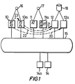
- the system shown in Figure 1 comprises a plurality of processors 10, 10a; 11, lla; 12, 12a; 14, 14a.
- the processors are interconnected by a data bus 15 which is in the form of a loop to permit communication between processors.
- the processors 10 and 10a form a pair of processors linked to external hardware item 16, the processors 11, lla are linked as a pair to external hardware item 17, and the processors 12, 12a are linked as a pair to a disc store 18.
- the processor 10 forms the primary hardware control processor for the hardware 16 and contains the hardware handler process for that hardware. This process is identified by the reference HI on Figure 1.
- the processor 11 comprises the main hardware control processor for the hardware 17 and that hardware handler process is identified by the reference H2.
- the disc store 18 contains load modules for all the hardware handler processes and software only processes operated by the system.
- processor 10 In addition to the hardware handler process H1 the processor 10 also contains a software only process identified by the reference F2.
- the processor 10a contains and is arranged to operate software only processes identified by references P3 and P4. Similar processes are contained within the processor lla and identified by the.references P6, P7, P8. Thus it will be seen that in normal operation of the system the duplicate or standby processors 10a and lla are operating software only processes so that use is made of these standby processors.
- the system shown in Figure 1 can be used to control many types of external hardware e.g. switching equipment in a telephone exchange.
- the processor lOa has to take over the hardware handler process function originally carried out by the processor 10.
- the first stage of recovery is to move the software only process P2 to a standby processor which in this case is the processor 12a. This operation is represented by the dotted line 20.
- the software only process P3 is moved to its standby processor which in this case is the processor 12. This is represented by the dotted line 21.
- the software only process P4 is also moved to the processor 12 as represented by the dotted line 22. Having moved the processes P3 and P4 from the processor 10a the hardware handler process H1 can then be moved into the standby processor 10a as represented by the dotted line 23.
- the dotted lines 21 to 23 are schematic illustrations only and in fact for example the load modules for Hl may not be physically moved from the processor 10 to 10a but may be drawn from the disc 18 via one of the processors 12 or 12a and fed into the processor lOa via the loop 15. Having moved the hardware handler process H1 to the processor 10a the software only processes P2, P3, P4 contained within the processors 12 and 12a can then be allocated to other spare processors such as those indicated by reference numerals 14, 14a. This then releases the processors 12, 12a for use in the manner similar to that described above should any further hardware handler processes fail.
- the present arrangement includes a set of paired or duplicated hardware controllers which are used in a way which reduces the overall hardware redundancy of the system necessary to maintain fault tolerance.
- the standby processor of each pair is used to operate software-only processes which are moved to other processors with spare capacity in the event of failure of the controller which is operating the hardware handler process.
- the arrangement is such that the total'unused or spare processing capacity can be reduced considerably over the prior art arrangements by making use of the spare capacity in the duplicated processors.
- Each software-only process can generally run on any processor having sufficient processing capacity of time and storage. Therefore, for software-only processes, the system need not be treated as a set of worker/standby pairs but as a single processing resource where allocation of processes to run on processors is determined primarily by the distribution and availability of processing capacity. Consequently the software-only processes can be allocated to standby hardware controller processors provided the recovery procedure for transferring these processes as described above is implemented.
- processing modules such as the modules 10, 10a; 11, lla; 12, 12a, shown in Figure 1, a module interconnection arrangement such as the ring or loop 15 of Figure 1, and an operating system.
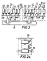
- FIG. 2 is a more detailed diagram showing the form which the processing modules can take.
- the module shown at 30 is connected to the ring 15 by an interface circuit 31.
- the module 30 comprises a CPU 32 which can be for example a Motorola 68000 microprocessor, a memory management unit 33, RAM's 34, and control circuitry 35 for interfacing with an item of external hardware 36, all of which are linked to a microprocessor bus 38.
- This configuration is a conventional configuration and hence will not be described in any more detail.
- the processing module shown at 40 in Figure 2 is similar to that shown at 30, the main difference being that the module 40 has a control circuit 41 for interfacing with the disc store 18 and a control circuit 42 for interfacing with a terminal 43.
- the module 40 has a control circuit 41 for interfacing with the disc store 18 and a control circuit 42 for interfacing with a terminal 43.
- the ring or loop 15 which interconnects the processing modules should have a high bandwidth, typically> 1M bit/sec. It is preferred that a braided type ring interconnection be employed for increased reliability.
- the interface circuit 31 can take the form shown in Figure 2a.
- the circuit includes a first part 45 which is connected in the braided ring 15 and carries out bit level functions including serial data transmission and reception, data coding and decoding, clock regeneration and bit synchronisation and braid switching.
- a second part 46 carries out message level functions including frame synchronisation, identification of address and control fields, error detection, token detection, bit stuffing and unstuffing and status indication.
- a third part 47 interfaces with the processing module and provides an interface to the processor bus 38, input and output buffering of messages to and from the processing module, and coordination of control between the processing module and the ring interface unit 45.
- FIG 3 is a simplified diagram showing a single processing module pair 50 50a and associated external hardware 51.
- the hardware 51 is controlled by a hardware handler process H1 which normally operates on processing module 50.
- Software-only processes P4, P7 operate on the processing module 50a.
- the operating system includes a system manager (SM) which is shown as operating on a processing module 52 and module managers (MM) which are distributed one to each processing module of the system.
- SM system manager
- MM module managers
- Each module manager MM performs internal management of its processing module and handles interprocessor communication. It responds to. commands from and reports to the system manager SM.
- the system manager SM is responsible for the overall supervision of the processor system, in particular for system maintenance and configuration management.
- the system manager SM can generally be centralised on a single processing module as shown in Figure 3 and incorporates the ability to restart itself on another processing module in the event of failure of the module on which it is .running.
- the system manager coordinates recovery from a processing module failure by issuing commands in the form of interprocessor messages to individual module managers.
- the system manager cyclically interrogates the processing modules to check their condition. If, for example, the interrogation of processing module 50 indicates that that module has failed, the system manager issues a command to the module manager of module 50 to cause processing on that module to cease.
- the system manager then issues a command which is transmitted to a further processing module 53.
- This command instructs the module manager of module 53 to create processes P4, P7 by allocating memory and downloading the process code and data from the store 18 and/or from the module 50a. These processes are held in a dormant state on module 53.
- the system manager then issues a command to the module manager of module 50a to terminate execution of processes P4, P7 following which it issues a command to module 53 to activate execution of processes P4, P7 on that processor.
- the system manager then issues a command to the module manager of module 50a to destroy processes P4 and P7 on that module and thereby make available the memory which was allocated to those processes.
- the system manager SM issues a command to module 50a to create process Hl and start that process.
- the module manager of module 50a allocates the necessary resources, downloads the process code and data for process H1 and activates the execution of that process.
- the final configuration is as shown in Figure 4 with H1 operating on the module 50a and processes P4, P7 on module 53.
- the operating system is designed to maintain the execution of processes in the event of a fault.
- a process is defined as the sequential execution of a series of program statements, the sequential execution of which may be concurrent with other processes. More than one "instance" of a process can exist, i.e. there can be more than one sequential execution of the same series of program statements. Each instance of a process has a name to which messages can be addressed.
- a process can send data to another process by sending a "message".
- a message includes the name of the destination process (instance).
- the present system can use the programming language CHILL (CCITT high level programming language) and the definitions of process and message applicable to that programming language apply in the present part of the description.
- CHILL CITT high level programming language
- the operating system is mainly composed of processes (except for the low level kernel of the module manager).
- the module manager part of the operating system as described previously is a group of processes which is resident on each processing module i.e. a separate set of instances of the module manager processes is on each processing module.
- the system manager is a single group of processes, i.e. there is only one instance of each process. As indicated with the reference to Figure 3 this is normally resident on one processing module but could be distributed over several- processing modules.
- Non-operating system processes are classified as application processes and include for example hardware handler processes.
- a message sent by a process is initially received by a Message Handler within the module manager of the processing module on which the message sender is resident (see Figure 5).
- the message handler MH reads the destination process (instance) name of the message. If the message is destined for a process on that module the message is attached to the input message queue of the process. Such a procedure is illustrated in Figure 5 for the processes C and D operating on the module 60. Data to be sent from process C is received by the message handler MH of module 60 and then directed to process D.
- the message is transmitted over the module interconnection link 15.
- The-link interface unit 31 on each processing module compares the destination address of this message with the names of its resident process instances and copies the message if there is a match.
- the message is then taken by the message handler of that processing module and attached to the input message queue of the destination process for reception by the process.
- Such a procedure is illustrated in Figure 5 for data sent by a process A from processing module 61 -to process E on processing module 60.
- This message form is transformed by the language compiler to a non-symbolic representation and is further transformed by the message handler MH of the processing module into a packet format which includes packet fields for source and destination addresses, message length and control information, and error checking.
- the frame format at the lowest level of communication is based on the HDLC (high level data link control) standard format.
- Messages requesting these operations are sent to a process handler in the module manager.
- the system manager sends messages requesting these operations to individual process handlers during the recovery procedure described above.
- the functions performed by a process handler in a module manager on reception of these messages are as follows:
- the control block is created for the process instance and the process instance set ready for execution.
- the process handler replies to the requesting process that the process instance has been created.
- the received message contains the name of the process instance to be started and the mode of starting e.g. initial start, rollback restart.
- the process handler activates execution of the named process instance, unless it has not been created in which case an error message is returned.
- the process handler terminates execution of the process instance named in the message, and sets it in a dormant state. It can be restarted by a start message. Messages addressed to the stop process instance are not accepted.
- the process handler frees all resources allocated to the process instance named in the message, e.g. memory used, and deletes all record of the process instance. Following this it would be necessary to create a process instance again if it were to be restarted.
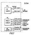
- FIGS 6 and 7 respectively illustrate the basic internal structure of the system manager and module manager in terms of the processes concerned with fault detection and recovery.
- the fault handling procedure is as follows.
- the states of processor modules are monitored by a processing module watchdog process 80 which forms part of the system manager.
- This watchdog process periodically requests status report messages from each module in turn.
- the watchdog process On receiving a failure report, or in the absence of an expected report, the watchdog process informs a fault diagnosis process 81.
- the diagnosis process correlates this information with other error report messages it may receive from processes in general. It validates and analyses the reports and informs a configuration manager 82 of its diagnosis.
- the configuration manager 82 maintains, in tables, a record of current state of the system in the form of a description of each processing module and each process. This includes-specifications of process module resources, process resource requirements, and the current allocation of process instances to the processing modules. This configuration description also includes standby process and module specifications from which the configuration'manager 82 can determine the reallocation of process instances to processor modules in the event of failure of a module. On receiving a process and module failure notification from the fault diagnosis process 81 the configuration manager determines what reallocation of process instances is needed for recovery. A message is sent to close down and isolate failed processing module.
- the watchdog process 80 requests and receives status messages from a processing module monitor process which operates on each processing module.
- a timer is kept for each processing module. On initial systems startup all the processing modules are set failed. Processing module status request messages are then sent and covering time out started. If a processing module on request is returned the timer for that processing module is reset. The processing module status is then changed to working. The processing status request messages are then sent at subsequent intervals. If a timer times out without the corresponding watchdog message being received the status is changed to failed.
- a report is sent to the fault diagnosis process 81 every time the processing module status changes. This is validated before being passed on to the configuration manager 82. The system manager then changes-its records concerning the system state and may migrate instances from one processing module to another depending on the new information.
- the fault diagnosis process receives processing module status reports from the watchdog process 80, and error reports and rollback requests from processes in general. It can request diagnostic tests to be carried out on a processing module. These reports are correlated, validated and logged. Fault diagnostic results are passed to the configuration manager 82.
- the configuration manager is a process which controls access to and updating of the data base defining the global system state. Three main sets of records are held:
- An initial definition of the system is loaded as a data file at initial system startup. Thereafter it is subject to updating by the configuration manager 82 in the event of faults or of commands respecifying the system via for example a keyboard terminal input.
- the configuration manager On receiving a message from a keyboard or fault diagnosis message requesting a reconfiguration of the system, the configuration manager determines the necessary changes from its records. It controls these changes and updates its records accordingly.
- the changes are carried out by sending instruction messages in an orderly sequence to the processes.
- the start/stop process 84 controls the starting and stopping of all non-kernel processes of the system.
- the start/stop process receives a request from the system manager.
- Starting and stopping of process instances may be part of a process migration sequence from one processing module to another or maybe merely an initial start or rollback restart on one processing module.
- the start/stop process handles the precise timing and synchronisation of the start and stop commands required for controlling execution of processes which are cooperating with the other processes.
- each module manager on the processing modules includes a processing module monitor 90 which runs an instance of this process. It is loaded immediately after the kernel on onitial system startup. The process performs basic checking of the operational state of the processing module. It periodically receives a message from the processing module watchdog on the system manager requesting a processing module status report. If the processing module monitor fails to send a response message the processing module watchdog, following a retry, assumes that the particular processing module has failed.
- the module manager also includes a process handler 91 which follows the state of process instances running on its processing module, maintaining an activation record and control block for each process instance. It performs the process schedule function. It also carries out create, start, stop and destroy operations on receipt of corresponding command messages received from the system manager. It calls on 'other functions in the module manager when carrying out these operations: for example creating a process instance may require-downloading process files by the processing module loader.
- a process handler 91 which follows the state of process instances running on its processing module, maintaining an activation record and control block for each process instance. It performs the process schedule function. It also carries out create, start, stop and destroy operations on receipt of corresponding command messages received from the system manager. It calls on 'other functions in the module manager when carrying out these operations: for example creating a process instance may require-downloading process files by the processing module loader.
- access to the loop or ring 15 can be by the control-token method.
- a control-token is a unique bit-string which is passed around the ring in a round-robin fashion from module to module.
- a module When a module is in possession of the token, it may delay passing it on and, instead, transmit the contents of its send buffer followed by the token.
- the next module in line relays all messages (there may be several) until it reads the token, and then either sends its own message (if it has one) followed by the token, or relays the token immediately. This sequence continues indefinitely around the ring.
- the interface of each module monitors the address field of passing messages.
Landscapes
- Engineering & Computer Science (AREA)
- Theoretical Computer Science (AREA)
- Quality & Reliability (AREA)
- Physics & Mathematics (AREA)
- General Engineering & Computer Science (AREA)
- General Physics & Mathematics (AREA)
- Hardware Redundancy (AREA)
- Multi Processors (AREA)
- Saccharide Compounds (AREA)
- Regulation And Control Of Combustion (AREA)
- Safety Devices In Control Systems (AREA)
- Jib Cranes (AREA)
- Preparation Of Compounds By Using Micro-Organisms (AREA)
- Electrotherapy Devices (AREA)
Priority Applications (1)
| Application Number | Priority Date | Filing Date | Title |
|---|---|---|---|
| AT82301607T ATE17408T1 (de) | 1981-03-31 | 1982-03-26 | Rechner- oder prozesssteuersysteme. |
Applications Claiming Priority (2)
| Application Number | Priority Date | Filing Date | Title |
|---|---|---|---|
| GB8110068 | 1981-03-31 | ||
| GB8110068 | 1981-03-31 |
Publications (2)
| Publication Number | Publication Date |
|---|---|
| EP0062463A1 true EP0062463A1 (de) | 1982-10-13 |
| EP0062463B1 EP0062463B1 (de) | 1986-01-08 |
Family
ID=10520801
Family Applications (1)
| Application Number | Title | Priority Date | Filing Date |
|---|---|---|---|
| EP82301607A Expired EP0062463B1 (de) | 1981-03-31 | 1982-03-26 | Rechner- oder Prozesssteuersysteme |
Country Status (11)
| Country | Link |
|---|---|
| US (1) | US4628508A (de) |
| EP (1) | EP0062463B1 (de) |
| JP (1) | JPS5812063A (de) |
| AT (1) | ATE17408T1 (de) |
| AU (1) | AU551032B2 (de) |
| CA (1) | CA1169155A (de) |
| DE (1) | DE3268359D1 (de) |
| IE (1) | IE52678B1 (de) |
| NZ (1) | NZ200170A (de) |
| PT (1) | PT74678B (de) |
| ZA (1) | ZA821999B (de) |
Cited By (5)
| Publication number | Priority date | Publication date | Assignee | Title |
|---|---|---|---|---|
| GB2195192A (en) * | 1986-09-19 | 1988-03-30 | Hitachi Ltd | System recovery method for computer system |
| FR2606184A1 (fr) * | 1986-10-31 | 1988-05-06 | Thomson Csf | Dispositif de calcul reconfigurable |
| EP0303855A3 (en) * | 1987-08-20 | 1990-02-07 | International Business Machines Corporation | Identification of data storage devices |
| EP0305068A3 (en) * | 1987-08-28 | 1990-06-27 | International Business Machines Corporation | Controlling asynchronously operating peripherals |
| US8799919B2 (en) | 2007-04-27 | 2014-08-05 | International Business Machines Corporation | Load balancing management of newly discovered data processing systems using peer control points |
Families Citing this family (40)
| Publication number | Priority date | Publication date | Assignee | Title |
|---|---|---|---|---|
| US4607365A (en) * | 1983-11-14 | 1986-08-19 | Tandem Computers Incorporated | Fault-tolerant communications controller system |
| US4882669A (en) * | 1983-11-28 | 1989-11-21 | Canon Kabushiki Kaisha | Multi computer fail safe control apparatus |
| US4823256A (en) * | 1984-06-22 | 1989-04-18 | American Telephone And Telegraph Company, At&T Bell Laboratories | Reconfigurable dual processor system |
| US5155678A (en) * | 1985-10-29 | 1992-10-13 | International Business Machines Corporation | Data availability in restartable data base system |
| US4819159A (en) * | 1986-08-29 | 1989-04-04 | Tolerant Systems, Inc. | Distributed multiprocess transaction processing system and method |
| SE454730B (sv) * | 1986-09-19 | 1988-05-24 | Asea Ab | Forfarande och datorutrustning for stotfri omkoppling av funktionen fran aktiva enheter till beredskapsenheter i en centralenhet |
| US5179715A (en) * | 1987-03-11 | 1993-01-12 | Toyo Communication Co., Ltd. | Multiprocessor computer system with process execution allocated by process managers in a ring configuration |
| US5121486A (en) * | 1987-11-20 | 1992-06-09 | Hitachi, Ltd | Network control system for dynamically switching a logical connection between an identified terminal device and an indicated processing unit |
| US5345587A (en) * | 1988-09-14 | 1994-09-06 | Digital Equipment Corporation | Extensible entity management system including a dispatching kernel and modules which independently interpret and execute commands |
| JP2723925B2 (ja) * | 1988-09-19 | 1998-03-09 | 株式会社日立製作所 | 計算機間プログラムオンライン再配置方式 |
| US4984240A (en) * | 1988-12-22 | 1991-01-08 | Codex Corporation | Distributed switching architecture for communication module redundancy |
| US5113522A (en) * | 1989-05-17 | 1992-05-12 | International Business Machines Corporation | Data processing system with system resource management for itself and for an associated alien processor |
| US5155809A (en) * | 1989-05-17 | 1992-10-13 | International Business Machines Corp. | Uncoupling a central processing unit from its associated hardware for interaction with data handling apparatus alien to the operating system controlling said unit and hardware |
| US5283868A (en) * | 1989-05-17 | 1994-02-01 | International Business Machines Corp. | Providing additional system characteristics to a data processing system through operations of an application program, transparently to the operating system |
| US5144692A (en) * | 1989-05-17 | 1992-09-01 | International Business Machines Corporation | System for controlling access by first system to portion of main memory dedicated exclusively to second system to facilitate input/output processing via first system |
| US5369767A (en) * | 1989-05-17 | 1994-11-29 | International Business Machines Corp. | Servicing interrupt requests in a data processing system without using the services of an operating system |
| US5325517A (en) * | 1989-05-17 | 1994-06-28 | International Business Machines Corporation | Fault tolerant data processing system |
| US5369749A (en) * | 1989-05-17 | 1994-11-29 | Ibm Corporation | Method and apparatus for the direct transfer of information between application programs running on distinct processors without utilizing the services of one or both operating systems |
| US5497497A (en) * | 1989-11-03 | 1996-03-05 | Compaq Computer Corp. | Method and apparatus for resetting multiple processors using a common ROM |
| JPH0747460B2 (ja) * | 1990-03-02 | 1995-05-24 | 株式会社日立製作所 | 乗客コンペアの制御装置 |
| EP0472861B1 (de) * | 1990-08-31 | 1995-09-20 | International Business Machines Corporation | Verfahren und Gerät zur Querteilungssteuerung in einer verteilten Verarbeitungsumgebung |
| JPH04156641A (ja) * | 1990-10-20 | 1992-05-29 | Fujitsu Ltd | レジスタアクセス装置 |
| ATE147568T1 (de) * | 1991-02-01 | 1997-01-15 | Siemens Ag | Verfahren für den fehlerbedingten neustart eines multiprozessorrechners eines fernmeldevermittlungssystems |
| US5815651A (en) * | 1991-10-17 | 1998-09-29 | Digital Equipment Corporation | Method and apparatus for CPU failure recovery in symmetric multi-processing systems |
| US5751932A (en) * | 1992-12-17 | 1998-05-12 | Tandem Computers Incorporated | Fail-fast, fail-functional, fault-tolerant multiprocessor system |
| US5838894A (en) | 1992-12-17 | 1998-11-17 | Tandem Computers Incorporated | Logical, fail-functional, dual central processor units formed from three processor units |
| DE9312739U1 (de) * | 1993-08-25 | 1993-10-07 | Siemens AG, 80333 München | Redundantes Automatisierungssystem |
| US5649152A (en) * | 1994-10-13 | 1997-07-15 | Vinca Corporation | Method and system for providing a static snapshot of data stored on a mass storage system |
| US5835953A (en) * | 1994-10-13 | 1998-11-10 | Vinca Corporation | Backup system that takes a snapshot of the locations in a mass storage device that has been identified for updating prior to updating |
| KR100212465B1 (ko) * | 1996-08-14 | 1999-08-02 | 정선종 | 객체지향 칠을 칠로 변환시 모레타 모드에 대한 그랜트/시즈 처 리 방법 |
| FI108599B (fi) * | 1999-04-14 | 2002-02-15 | Ericsson Telefon Ab L M | Toipuminen matkaviestinjärjestelmissä |
| EP1912124B8 (de) | 1999-10-14 | 2013-01-09 | Bluearc UK Limited | Vorrichtung und System zur Ausführung von Betriebsfunktionen |
| JP2001256066A (ja) * | 2000-02-29 | 2001-09-21 | Internatl Business Mach Corp <Ibm> | コンピュータシステム、オペレーティングシステムの切り替えシステム、オペレーティングシステムの実装方法、オペレーティングシステムの切り替え方法、記憶媒体及びプログラム伝送装置 |
| US7113938B2 (en) | 2002-02-14 | 2006-09-26 | Gravic, Inc. | Method of increasing system availability by splitting a system |
| US20030172106A1 (en) * | 2002-02-14 | 2003-09-11 | Iti, Inc. | Method of increasing system availability by assigning process pairs to processor pairs |
| US7457822B1 (en) | 2002-11-01 | 2008-11-25 | Bluearc Uk Limited | Apparatus and method for hardware-based file system |
| US8041735B1 (en) | 2002-11-01 | 2011-10-18 | Bluearc Uk Limited | Distributed file system and method |
| EP1674955A1 (de) * | 2004-12-23 | 2006-06-28 | Siemens Aktiengesellschaft | Verfahren und Vorrichtung zur Überwachung der Funktionsweise eines Automatisierungssystems einer technischen Anlage |
| EP2992393B1 (de) * | 2013-04-29 | 2019-09-11 | Essilor International | Berechnungssystem zur herstellung einer ophthalmischen linse |
| EP3456674B1 (de) | 2017-09-15 | 2020-04-01 | Otis Elevator Company | Schlaffheitsdetektionssystem eines aufzugsspannelements und verfahren zur durchführung eines not-aus-betriebs eines aufzugssystems |
Citations (3)
| Publication number | Priority date | Publication date | Assignee | Title |
|---|---|---|---|---|
| US3377623A (en) * | 1965-09-29 | 1968-04-09 | Foxboro Co | Process backup system |
| GB1243464A (en) * | 1969-01-17 | 1971-08-18 | Plessey Telecomm Res Ltd | Stored-programme controlled data-processing systems |
| US3623014A (en) * | 1969-08-25 | 1971-11-23 | Control Data Corp | Computer communications system |
Family Cites Families (8)
| Publication number | Priority date | Publication date | Assignee | Title |
|---|---|---|---|---|
| DE2202231A1 (de) * | 1972-01-18 | 1973-07-26 | Siemens Ag | Verarbeitungssystem mit verdreifachten systemeinheiten |
| US4228496A (en) * | 1976-09-07 | 1980-10-14 | Tandem Computers Incorporated | Multiprocessor system |
| US4071704A (en) * | 1977-01-26 | 1978-01-31 | Trw, Inc. | Service generator checking apparatus |
| US4358823A (en) * | 1977-03-25 | 1982-11-09 | Trw, Inc. | Double redundant processor |
| US4133027A (en) * | 1977-09-13 | 1979-01-02 | Honeywell Inc. | Process control system with backup process controller |
| US4195351A (en) * | 1978-01-27 | 1980-03-25 | International Business Machines Corporation | Loop configured data transmission system |
| JPS55146552A (en) * | 1979-05-02 | 1980-11-14 | Hitachi Ltd | N 1 backkup method of dispersion type hierarchy system |
| US4351023A (en) * | 1980-04-11 | 1982-09-21 | The Foxboro Company | Process control system with improved system security features |
-
1982
- 1982-03-24 ZA ZA821999A patent/ZA821999B/xx unknown
- 1982-03-24 AU AU81853/82A patent/AU551032B2/en not_active Ceased
- 1982-03-26 AT AT82301607T patent/ATE17408T1/de not_active IP Right Cessation
- 1982-03-26 DE DE8282301607T patent/DE3268359D1/de not_active Expired
- 1982-03-26 EP EP82301607A patent/EP0062463B1/de not_active Expired
- 1982-03-29 CA CA000399689A patent/CA1169155A/en not_active Expired
- 1982-03-29 IE IE752/82A patent/IE52678B1/en not_active IP Right Cessation
- 1982-03-30 PT PT74678A patent/PT74678B/pt not_active IP Right Cessation
- 1982-03-30 NZ NZ200170A patent/NZ200170A/en unknown
- 1982-03-31 JP JP57053629A patent/JPS5812063A/ja active Granted
-
1985
- 1985-05-07 US US06/731,617 patent/US4628508A/en not_active Expired - Lifetime
Patent Citations (3)
| Publication number | Priority date | Publication date | Assignee | Title |
|---|---|---|---|---|
| US3377623A (en) * | 1965-09-29 | 1968-04-09 | Foxboro Co | Process backup system |
| GB1243464A (en) * | 1969-01-17 | 1971-08-18 | Plessey Telecomm Res Ltd | Stored-programme controlled data-processing systems |
| US3623014A (en) * | 1969-08-25 | 1971-11-23 | Control Data Corp | Computer communications system |
Cited By (9)
| Publication number | Priority date | Publication date | Assignee | Title |
|---|---|---|---|---|
| US4977500A (en) * | 1986-09-09 | 1990-12-11 | Hitachi, Ltd. | System recovery method for computer system having a standby system with a wait job operation capability |
| GB2195192A (en) * | 1986-09-19 | 1988-03-30 | Hitachi Ltd | System recovery method for computer system |
| GB2195192B (en) * | 1986-09-19 | 1990-10-17 | Hitachi Ltd | System recovery method for computer system |
| FR2606184A1 (fr) * | 1986-10-31 | 1988-05-06 | Thomson Csf | Dispositif de calcul reconfigurable |
| EP0272165A1 (de) * | 1986-10-31 | 1988-06-22 | Thomson-Csf | Rekonfigurierbare Rechenanordnung |
| EP0303855A3 (en) * | 1987-08-20 | 1990-02-07 | International Business Machines Corporation | Identification of data storage devices |
| US5148540A (en) * | 1987-08-20 | 1992-09-15 | International Business Machines Corporation | System with backup of data storage status and device identification for enabling system recovery after powerloss |
| EP0305068A3 (en) * | 1987-08-28 | 1990-06-27 | International Business Machines Corporation | Controlling asynchronously operating peripherals |
| US8799919B2 (en) | 2007-04-27 | 2014-08-05 | International Business Machines Corporation | Load balancing management of newly discovered data processing systems using peer control points |
Also Published As
| Publication number | Publication date |
|---|---|
| PT74678B (en) | 1983-10-25 |
| EP0062463B1 (de) | 1986-01-08 |
| IE52678B1 (en) | 1988-01-20 |
| DE3268359D1 (en) | 1986-02-20 |
| ATE17408T1 (de) | 1986-01-15 |
| CA1169155A (en) | 1984-06-12 |
| PT74678A (en) | 1982-04-01 |
| AU551032B2 (en) | 1986-04-17 |
| IE820752L (en) | 1982-09-19 |
| NZ200170A (en) | 1984-08-24 |
| US4628508A (en) | 1986-12-09 |
| AU8185382A (en) | 1982-10-07 |
| JPS5812063A (ja) | 1983-01-24 |
| ZA821999B (en) | 1983-05-25 |
| JPH0145658B2 (de) | 1989-10-04 |
Similar Documents
| Publication | Publication Date | Title |
|---|---|---|
| EP0062463B1 (de) | Rechner- oder Prozesssteuersysteme | |
| US8375363B2 (en) | Mechanism to change firmware in a high availability single processor system | |
| US5784617A (en) | Resource-capability-based method and system for handling service processor requests | |
| FI101432B (fi) | Vikasietoinen tietokonejärjestelmä | |
| EP1099164B1 (de) | Verfahren und programm zum verarbeiten der verwaltungsanfragen einer verteilten netzwerkanwendung in einer gruppierten rechnerumgebung | |
| KR100575497B1 (ko) | 내고장성 컴퓨터 시스템 | |
| US7076689B2 (en) | Use of unique XID range among multiple control processors | |
| US7188237B2 (en) | Reboot manager usable to change firmware in a high availability single processor system | |
| US20040153624A1 (en) | High availability synchronization architecture | |
| US4144407A (en) | Multiprocessor system for automatic switching of telegraphic lines | |
| US7065673B2 (en) | Staged startup after failover or reboot | |
| CN111209110B (zh) | 一种实现负载均衡的任务调度管理方法、系统和存储介质 | |
| WO2012000997A1 (en) | An apparatus for processing a batched unit of work | |
| JP4634058B2 (ja) | 実時間遠隔バックアップシステム及びそのバックアップ方法 | |
| KR19990043986A (ko) | 업무 인계 시스템 | |
| CN114564340A (zh) | 航天地面系统分布式软件高可用方法 | |
| Li et al. | Fault-tolerant cluster management for reliable high-performance computing | |
| US5446875A (en) | System to pass through resource information | |
| US6370654B1 (en) | Method and apparatus to extend the fault-tolerant abilities of a node into a network | |
| JPH0736721A (ja) | 多重化コンピュータシステムの制御方式 | |
| JPH05241857A (ja) | データ処理装置 | |
| KR100408979B1 (ko) | 무선통신시스템에서 프로세서 이중화를 위한 결함 허용장치 및 그 방법 | |
| CN113965561B (zh) | 一种基于异步事件驱动的机载文件传输系统 | |
| Deconinck et al. | A framework backbone for software fault tolerance in embedded parallel applications | |
| Hull et al. | Virtual resource ring: Technique for decentralised resource management in fault-tolerant distributed computer systems |
Legal Events
| Date | Code | Title | Description |
|---|---|---|---|
| PUAI | Public reference made under article 153(3) epc to a published international application that has entered the european phase |
Free format text: ORIGINAL CODE: 0009012 |
|
| AK | Designated contracting states |
Designated state(s): AT BE CH DE FR GB IT LU NL SE |
|
| 17P | Request for examination filed |
Effective date: 19830218 |
|
| GRAA | (expected) grant |
Free format text: ORIGINAL CODE: 0009210 |
|
| AK | Designated contracting states |
Designated state(s): AT BE CH DE FR GB IT LI LU NL SE |
|
| REF | Corresponds to: |
Ref document number: 17408 Country of ref document: AT Date of ref document: 19860115 Kind code of ref document: T |
|
| ITF | It: translation for a ep patent filed | ||
| REF | Corresponds to: |
Ref document number: 3268359 Country of ref document: DE Date of ref document: 19860220 |
|
| ET | Fr: translation filed | ||
| PLBI | Opposition filed |
Free format text: ORIGINAL CODE: 0009260 |
|
| 26 | Opposition filed |
Opponent name: SIEMENS AKTIENGESELLSCHAFT, BERLIN UND MUENCHEN Effective date: 19860925 |
|
| NLR1 | Nl: opposition has been filed with the epo |
Opponent name: SIEMENS AKTIENGESELLSCHAFT |
|
| PLBN | Opposition rejected |
Free format text: ORIGINAL CODE: 0009273 |
|
| STAA | Information on the status of an ep patent application or granted ep patent |
Free format text: STATUS: OPPOSITION REJECTED |
|
| 27O | Opposition rejected |
Effective date: 19881009 |
|
| NLR2 | Nl: decision of opposition | ||
| REG | Reference to a national code |
Ref country code: CH Ref legal event code: PUE Owner name: BRITISH TELECOMMUNICATIONS PUBLIC LIMITED COMPANY |
|
| REG | Reference to a national code |
Ref country code: FR Ref legal event code: TP |
|
| ITTA | It: last paid annual fee | ||
| PGFP | Annual fee paid to national office [announced via postgrant information from national office to epo] |
Ref country code: CH Payment date: 19940211 Year of fee payment: 13 |
|
| PGFP | Annual fee paid to national office [announced via postgrant information from national office to epo] |
Ref country code: AT Payment date: 19940214 Year of fee payment: 13 |
|
| PGFP | Annual fee paid to national office [announced via postgrant information from national office to epo] |
Ref country code: LU Payment date: 19940331 Year of fee payment: 13 |
|
| ITPR | It: changes in ownership of a european patent |
Owner name: CESSIONE;BRITISH TELECOMMUNICATIONS PLC |
|
| EPTA | Lu: last paid annual fee | ||
| NLS | Nl: assignments of ep-patents |
Owner name: BRITISH TELECOMMUNICATIONS PLC TE LONDEN, GROOT-BR |
|
| EAL | Se: european patent in force in sweden |
Ref document number: 82301607.6 |
|
| PG25 | Lapsed in a contracting state [announced via postgrant information from national office to epo] |
Ref country code: LU Free format text: LAPSE BECAUSE OF NON-PAYMENT OF DUE FEES Effective date: 19950326 Ref country code: AT Effective date: 19950326 |
|
| PG25 | Lapsed in a contracting state [announced via postgrant information from national office to epo] |
Ref country code: LI Effective date: 19950331 Ref country code: CH Effective date: 19950331 |
|
| REG | Reference to a national code |
Ref country code: CH Ref legal event code: PL |
|
| PGFP | Annual fee paid to national office [announced via postgrant information from national office to epo] |
Ref country code: SE Payment date: 19980217 Year of fee payment: 17 |
|
| PGFP | Annual fee paid to national office [announced via postgrant information from national office to epo] |
Ref country code: NL Payment date: 19980228 Year of fee payment: 17 |
|
| PGFP | Annual fee paid to national office [announced via postgrant information from national office to epo] |
Ref country code: BE Payment date: 19980320 Year of fee payment: 17 |
|
| PG25 | Lapsed in a contracting state [announced via postgrant information from national office to epo] |
Ref country code: SE Free format text: LAPSE BECAUSE OF NON-PAYMENT OF DUE FEES Effective date: 19990327 |
|
| PG25 | Lapsed in a contracting state [announced via postgrant information from national office to epo] |
Ref country code: BE Free format text: LAPSE BECAUSE OF NON-PAYMENT OF DUE FEES Effective date: 19990331 |
|
| BERE | Be: lapsed |
Owner name: BRITISH TELECOMMUNICATIONS Effective date: 19990331 |
|
| PG25 | Lapsed in a contracting state [announced via postgrant information from national office to epo] |
Ref country code: NL Free format text: LAPSE BECAUSE OF NON-PAYMENT OF DUE FEES Effective date: 19991001 |
|
| EUG | Se: european patent has lapsed |
Ref document number: 82301607.6 |
|
| NLV4 | Nl: lapsed or anulled due to non-payment of the annual fee |
Effective date: 19991001 |
|
| EUG | Se: european patent has lapsed |
Ref document number: 82301607.6 |
|
| PGFP | Annual fee paid to national office [announced via postgrant information from national office to epo] |
Ref country code: FR Payment date: 20010208 Year of fee payment: 20 |
|
| PGFP | Annual fee paid to national office [announced via postgrant information from national office to epo] |
Ref country code: GB Payment date: 20010219 Year of fee payment: 20 |
|
| PGFP | Annual fee paid to national office [announced via postgrant information from national office to epo] |
Ref country code: DE Payment date: 20010222 Year of fee payment: 20 |
|
| REG | Reference to a national code |
Ref country code: GB Ref legal event code: IF02 |
|
| PG25 | Lapsed in a contracting state [announced via postgrant information from national office to epo] |
Ref country code: GB Free format text: LAPSE BECAUSE OF EXPIRATION OF PROTECTION Effective date: 20020325 |
|
| REG | Reference to a national code |
Ref country code: GB Ref legal event code: PE20 Effective date: 20020325 |