EP0062619B1 - Véhicules mélangeurs de béton - Google Patents
Véhicules mélangeurs de béton Download PDFInfo
- Publication number
- EP0062619B1 EP0062619B1 EP82830074A EP82830074A EP0062619B1 EP 0062619 B1 EP0062619 B1 EP 0062619B1 EP 82830074 A EP82830074 A EP 82830074A EP 82830074 A EP82830074 A EP 82830074A EP 0062619 B1 EP0062619 B1 EP 0062619B1
- Authority
- EP
- European Patent Office
- Prior art keywords
- discharge duct
- duct
- arm
- telescopic
- concrete mixer
- Prior art date
- Legal status (The legal status is an assumption and is not a legal conclusion. Google has not performed a legal analysis and makes no representation as to the accuracy of the status listed.)
- Expired
Links
- 230000002427 irreversible effect Effects 0.000 claims description 3
- 239000000463 material Substances 0.000 claims description 2
- 230000004913 activation Effects 0.000 claims 1
- 238000006073 displacement reaction Methods 0.000 claims 1
- 239000012530 fluid Substances 0.000 claims 1
- 230000000284 resting effect Effects 0.000 claims 1
- 239000000203 mixture Substances 0.000 abstract description 9
- 230000004323 axial length Effects 0.000 abstract 2
- 238000009415 formwork Methods 0.000 description 3
- 238000004140 cleaning Methods 0.000 description 2
- 230000008878 coupling Effects 0.000 description 2
- 238000010168 coupling process Methods 0.000 description 2
- 238000005859 coupling reaction Methods 0.000 description 2
- 230000000694 effects Effects 0.000 description 2
- 238000007599 discharging Methods 0.000 description 1
- 238000001125 extrusion Methods 0.000 description 1
- 230000002093 peripheral effect Effects 0.000 description 1
- 229920003023 plastic Polymers 0.000 description 1
- 239000004033 plastic Substances 0.000 description 1
- 229920000642 polymer Polymers 0.000 description 1
- XLYOFNOQVPJJNP-UHFFFAOYSA-N water Substances O XLYOFNOQVPJJNP-UHFFFAOYSA-N 0.000 description 1
- 238000003466 welding Methods 0.000 description 1
Images


Classifications
-
- B—PERFORMING OPERATIONS; TRANSPORTING
- B28—WORKING CEMENT, CLAY, OR STONE
- B28C—PREPARING CLAY; PRODUCING MIXTURES CONTAINING CLAY OR CEMENTITIOUS MATERIAL, e.g. PLASTER
- B28C5/00—Apparatus or methods for producing mixtures of cement with other substances, e.g. slurries, mortars, porous or fibrous compositions
- B28C5/42—Apparatus specially adapted for being mounted on vehicles with provision for mixing during transport
- B28C5/4203—Details; Accessories
- B28C5/4234—Charge or discharge systems therefor
- B28C5/4244—Discharging; Concrete conveyor means, chutes or spouts therefor
- B28C5/4248—Discharging; Concrete conveyor means, chutes or spouts therefor using chutes
- B28C5/4251—Discharging; Concrete conveyor means, chutes or spouts therefor using chutes telescopic or foldable chutes
-
- B—PERFORMING OPERATIONS; TRANSPORTING
- B65—CONVEYING; PACKING; STORING; HANDLING THIN OR FILAMENTARY MATERIAL
- B65G—TRANSPORT OR STORAGE DEVICES, e.g. CONVEYORS FOR LOADING OR TIPPING, SHOP CONVEYOR SYSTEMS OR PNEUMATIC TUBE CONVEYORS
- B65G11/00—Chutes
- B65G11/14—Chutes extensible, e.g. telescopic
- B65G11/146—Chutes extensible, e.g. telescopic for bulk
Definitions
- the present invention relates to a telescopic discharge duct for a concrete mixer truck of the kind defined in the preamble of the appended claim 1.
- US-A-2968382 discloses a discharge duct of the above type, which includes a plurality of chute sections and can be extended and retracted by means of a cylinder placed under the chute sections. Each section is guided and supported by an adjacent section so that in operation each section must sustain the weight of all the following sections and the concrete flowing on it and all the following sections.
- the chute sections are heavily stressed and can be easily deformed so as to make the extrusion and retraction of the discharge duct more difficult or even no longer possible.
- the maximum length of this known discharge duct is limited.
- US-A-3481440 discloses power means for rotating a discharge duct of a concrete mixer truck about a vertical axis and for raising or lowering the duct.
- the main object of the invention is to provide a telescopic discharge duct of improved design, which allows the drawbacks of the prior devices to be overcome.
- a concrete mixer truck is indicated 1, the chassis of which is provided with a framework 2 which supports a concrete mixer 3 in the form of a drum rotatable about an inclined axis lying in the medial longitudinal plane of the vehicle.
- the rear end of the concrete mixer 3 is provided with a loading hopper 4 and a lower discharge opening 5.
- a discharge duct, generally indicated 6, is supported by the framework 2 beneath the discharge opening 5 of the concrete mixer.
- the discharge duct 6 can be extended and shortened continuously in the axial direction.
- Figure 1 shows the discharge duct 6 in its configuration of maximum length.
- Figure 2 illustrates the discharge duct 6 in its configuration of minimum length.
- a vertical plate 7 is fixed to the rear end of framework 2 of the truck.
- a sleeve 8 is fixed to the vertical end edge of the plate 7.
- a shaft 9 Within the sleeve 8 is rotatably mounted a shaft 9, to the upper end of which is fixed an arm 10.
- a first duct element 11 is connected to the upper end of the arm 10 so as to be rotatable about a horizontal axis X-X. Adjacent the arm 10, the facing side walls of the duct element 11 are connected by a lateral wall 11a. The end portion of the duct element 11 facing the arm 10 is always located below the discharge opening 5 of the concrete mixer 3.
- first and second fork elements 13, 14 are connected, so as to be rotatable about a horizontal axis Y-Y parallel to the axis X-X.
- the fork elements 13, 14 are connected together by a shaft 15 which extends in the direction of the axis Y-Y through facing apertures formed in the side walls of the duct element 11.
- first and second double-acting hydraulic cylinders supported by the fork elements 14 and 13 respectively so as to be rotatable about respective axes Z 1 -Z 1' Z Z -Z 2 , which are parallel to each other and perpendicular to the axis Y-Y.
- the hydraulic cylinders 17,18 have respectively rods 19, 20.
- first and second pantograph support structures each constituted by a succession of articulated parallelograms of equal sizes disposed in respective vertical planes.
- the pantograph structures 21, 22 are similar and parallel to each other.
- the articulated parallelograms of the structures 21, 22 at the ends adjacent the truck 3 are connected, so as to be rotatable about a horizontal axis, to the ends of the two arms of a fork element 25 which surrounds the lower part of the element 11.
- the fork element 25 is connected to the rod 26 of a single acting hydraulic cylinder 27.
- the end of the body of the hydraulic cylinder 27 opposite the fork 25 is connected to a radial lug 9a at the lower end of the shaft 9, so as to be rotatable about a horizontal axis parallel to the said axis X-X.
- the lug 9a of the shaft 9 is preferably shaped in the form of a fork.
- each articulated joint of the pantograph structure 21 common to two adjacent articulated parallelograms of this structure, there is rotatably connected a first end of a respective C-shaped bracket 30 the concavity of which faces upwardly and the other end of which is rotatably connected to the homologous articulated joint of the other support structure 22.
- One end of a respective duct element 31 is attached to each bracket 30 for example by welding. The other end of each duct element 31 rests on the upper surface of the adjacent duct element 31.
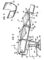
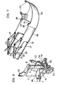
- each duct element 31, close to the end opposite the respective bracket 30, has a plurality of longitudinal projections 32 ( Figures 3 and 4) for facilitating the relative sliding of the respective duct element and the adjacent duct element.
- an end duct element which is rotatably connected to the end articulated joints of the pantograph structures 21, 22.
- the duct element 35 has two parallel arms 36 extending towards the concrete mixer 3, the upper edge of each arm 36 bearing against a respective stop pin 37 carried by the pantograph structures 21 and 22 respectively, close to the articulated joint which is common to the two end articulated parallelograms.
- first and second pins carried by the upper edge of the duct element 35 in that end portion opposite the concrete mixer.
- a disc 40 lying in a substantially horizontal plane and provided with a ring of substantially equispaced holes 41.
- a handwheel 42 lying in a substantially horizontal plane, is connected to the disc 40 by spokes 43.
- a bracket 45 disposed in a substantially horizontal plane, is rigidly connected to the lower part of the plate 7.
- This bracket has a hole 46 for receiving a stop pin 47.
- the lower end of this pin is adapted to engage a hole 41 in the disc 40 connected to the lower part of the shaft 9 to lock this disc, the handwheel 42 and the shaft 9 in a predetermined angular position.
- the discharge duct 6 In use, during the stage of transporting the concrete mixture, the discharge duct 6 is maintained in the retracted condition, in a position rotated through 90° (about the vertical) relative to that illustrated in Figure 2. Under these conditions the discharge duct 6 has a minimum extent.
- the concrete mixer truck When the place of use is reached, the concrete mixer truck is stopped close to the formwork or other structure intended to receive the concrete mixture contained in the concrete mixer 3.
- the driver leaves his driving position and orientates the discharge duct 6 by operating the handwheel 42.
- first and second manually controlled hydraulic pumps 70, 71 ( Figures 1 and 2) arranged to actuate the cylinders 17, 18 and the cylinder 27 respectively.
- the pump 70 By actuating the pump 70, the operator can cause the rods 19, 20 to extend out from the cylinders 17, 18. Consequently the pantograph structures 21, 22 extend, causing the duct elements 31 to slide relative to each other.
- the overall length of the discharge duct 6 increases continuously. The operator stops the actuation of the cylinders 17, 18 as soon as the duct 6 has reached the desired length.
- the operator can rotate the discharge duct 6 upwardly or downwardly about the axis X-X by actuating the hydraulic pump 71 connected to cylinder 27.
- the actuation of this cylinder effects translational movement of the rod 26 of this cylinder and consequently rotation of the duct 6 about the said axis X-X, by means of the fork element 25.
- the operator can also change the angular position of the duct 6 relative to the longitudinal median axis of the concrete mixer truck. For this purpose it suffices for the operator to unlock the handwheel 42, by extracting the pin 47 from the hole 46 in the bracket 45. Once this operation has been effected, the operator can change the position of the duct 6 by rotating the handwheel 42. When the desired angular position is reached, the handwheel 42 can again be locked in position by the introduction of the pin 47 into the hole 46 of the bracket 45 and into the hole 41 of the disc 40 corresponding to the desired position.
- the discharge duct according to the invention eliminates the problem of carrying out the manoeuvres for positioning and bringing the concrete mixer truck close to the formwork (or other structure) intended to receive the concrete in the concrete mixer. Moreover, only a single operator is needed to position the end of the discharge duct 6 correctly relative to the formwork.
- the discharge duct 6 illustrated in Figure 3 may easily be cleaned. This cleaning operation may be carried out simply by means of a jet of water and is facilitated by the possibility of rotating each duct element 31 upwardly independently of the adjacent duct element, as illustrated in Figure 5.
- the rotation of the discharge duct 6 about the vertical axis may be controlled by means of a worm 50 rotatably supported by two arms 51 fixed to two brackets 45 rigid with the vertical plate 7 described above.
- the worm 50 is provided at one end with a handwheel 53.
- a helically toothed worm wheel 54 To the lower end of the shaft 9 there is connected a helically toothed worm wheel 54 the peripheral teeth of which engage the worm 50.
- the coupling between the worm 50 and the worm wheel 54 is preferably of the irreversible type. Rotation of the wheel 53, through the worm 50 and the worm wheel 54, effects rotation of the shaft 9 and hence of the discharge duct 6. If, as has been indicated above, the coupling between the worm 50 and the worm wheel 54 is of irreversible type, no further means are necessary for locking the discharge duct 6 in the desired angular position.
- the discharge duct 6 described above may be fitted with a further duct element 60 provided, at one end, with a pair of lugs 61 each of which is formed with a hole for engagement by respective pin 38 carried by the end duct element 35.
- the duct element 60 is curved and may be used for the lateral discharge of the concrete mixture from the concrete mixer 3 towards a receiving structure. More particularly, the duct element 60 may be used for directing a jet of concrete mixture into a lateral receiving structure, with the concrete mixer truck moving along this receiving structure.
- the curved duct element 60 preferably has a second pair of lugs 62 also provided with respective holes, and at the opposite end from the lugs 61. Thanks to this device, it is possible to use the same curved duct element for discharging the concrete mixture on one side of the vehicle or on the other side.
- the duct elements 31, 35 and 60 may conveniently be formed in plastics material (polymer) to allow improved sliding of the mixture, a lighter structure for the discharge duct and easier cleaning of the latter.
Landscapes
- Engineering & Computer Science (AREA)
- Mechanical Engineering (AREA)
- Structural Engineering (AREA)
- Preparation Of Clay, And Manufacture Of Mixtures Containing Clay Or Cement (AREA)
- On-Site Construction Work That Accompanies The Preparation And Application Of Concrete (AREA)
- Organic Low-Molecular-Weight Compounds And Preparation Thereof (AREA)
Claims (9)
Priority Applications (1)
| Application Number | Priority Date | Filing Date | Title |
|---|---|---|---|
| AT82830074T ATE20451T1 (de) | 1981-04-06 | 1982-03-25 | Betonliefermischerfahrzeuge. |
Applications Claiming Priority (2)
| Application Number | Priority Date | Filing Date | Title |
|---|---|---|---|
| IT8167480A IT1143533B (it) | 1981-04-06 | 1981-04-06 | Perfezionamenti nelle autobetoniere |
| IT6748081 | 1981-04-06 |
Publications (2)
| Publication Number | Publication Date |
|---|---|
| EP0062619A1 EP0062619A1 (fr) | 1982-10-13 |
| EP0062619B1 true EP0062619B1 (fr) | 1986-06-18 |
Family
ID=11302761
Family Applications (1)
| Application Number | Title | Priority Date | Filing Date |
|---|---|---|---|
| EP82830074A Expired EP0062619B1 (fr) | 1981-04-06 | 1982-03-25 | Véhicules mélangeurs de béton |
Country Status (4)
| Country | Link |
|---|---|
| EP (1) | EP0062619B1 (fr) |
| AT (1) | ATE20451T1 (fr) |
| DE (1) | DE3271740D1 (fr) |
| IT (1) | IT1143533B (fr) |
Cited By (1)
| Publication number | Priority date | Publication date | Assignee | Title |
|---|---|---|---|---|
| DE19845573A1 (de) * | 1998-10-02 | 2000-04-06 | Vaw Ver Aluminium Werke Ag | Silofahrzeug |
Families Citing this family (9)
| Publication number | Priority date | Publication date | Assignee | Title |
|---|---|---|---|---|
| US5035313A (en) * | 1990-05-07 | 1991-07-30 | Felesta Smith | Telescopic chute for a mixer truck |
| FI932970L (fi) * | 1993-06-28 | 1994-12-29 | Laite Saraka | Betoninkuljetussekoitin tai vastaava |
| FR2728147A1 (fr) * | 1994-12-15 | 1996-06-21 | Garralon Pierre | Table telescopique a rouleaux, a deploiement assiste |
| GB2326407B (en) * | 1997-05-14 | 1999-06-02 | Ian Dennis Mccarthy | Sectional Chute |
| ES2245553B1 (es) * | 2003-06-03 | 2007-03-16 | Concepcion Gonzalez Embid | Brazo giratorio para canal de descarga de tolva de hormigonera. |
| CN101053980B (zh) * | 2007-04-27 | 2011-04-06 | 三一重工股份有限公司 | 带举升装置的混凝土搅拌运输车 |
| CN102673936A (zh) * | 2012-05-16 | 2012-09-19 | 武汉理工大学 | 可自动调节长度的溜筒装置 |
| CN106629101A (zh) * | 2016-11-29 | 2017-05-10 | 山东希成农业机械科技有限公司 | 一种智能马铃薯堆垛机 |
| CN116356828B (zh) * | 2023-05-24 | 2023-11-10 | 江苏力引建材科技股份有限公司 | 一种水利支护冠梁的混凝土浇筑设备 |
Family Cites Families (5)
| Publication number | Priority date | Publication date | Assignee | Title |
|---|---|---|---|---|
| US2968382A (en) * | 1957-12-02 | 1961-01-17 | Oury John Foster | Telescopic chute |
| US3157262A (en) * | 1963-04-01 | 1964-11-17 | Chapdelaine Louis Philippe | Telescopic chute |
| US3481440A (en) * | 1967-08-08 | 1969-12-02 | Monarch Road Machinery Co | Power means for a cement discharge chute |
| US4190144A (en) * | 1978-06-09 | 1980-02-26 | Lybbert Evart K | Concrete discharge chutes |
| FR2451334A1 (fr) * | 1979-03-15 | 1980-10-10 | Castera Pierre | Distributeur controle pour granulats fragiles ou toxiques |
-
1981
- 1981-04-06 IT IT8167480A patent/IT1143533B/it active
-
1982
- 1982-03-25 EP EP82830074A patent/EP0062619B1/fr not_active Expired
- 1982-03-25 AT AT82830074T patent/ATE20451T1/de not_active IP Right Cessation
- 1982-03-25 DE DE8282830074T patent/DE3271740D1/de not_active Expired
Cited By (1)
| Publication number | Priority date | Publication date | Assignee | Title |
|---|---|---|---|---|
| DE19845573A1 (de) * | 1998-10-02 | 2000-04-06 | Vaw Ver Aluminium Werke Ag | Silofahrzeug |
Also Published As
| Publication number | Publication date |
|---|---|
| EP0062619A1 (fr) | 1982-10-13 |
| DE3271740D1 (en) | 1986-07-24 |
| IT8167480A0 (it) | 1981-04-06 |
| IT1143533B (it) | 1986-10-22 |
| ATE20451T1 (de) | 1986-07-15 |
Similar Documents
| Publication | Publication Date | Title |
|---|---|---|
| US5895197A (en) | Cable reel handler | |
| US5092731A (en) | Container handling apparatus for a refuse collection vehicle | |
| EP1616996B1 (fr) | Fraiseuse | |
| US4710055A (en) | Riding-type multiple trowel machine | |
| US5419671A (en) | Top mounted container handling apparatus | |
| GB2230507A (en) | Tiltable tailgate lift | |
| US5035313A (en) | Telescopic chute for a mixer truck | |
| US7152709B2 (en) | Industrial vehicle | |
| US6851486B2 (en) | Grading attachment for a loader | |
| GB1591915A (en) | Loading device for goods vehicles | |
| EP0062619A1 (fr) | Véhicules mélangeurs de béton | |
| US4019781A (en) | Hydraulic hoist for pickup bed | |
| US5549359A (en) | Dual use materials transport vehicle with end-dumping and improved belly-dumping capabilities and method of construction | |
| US4799556A (en) | Drilling boom | |
| EP3342636B1 (fr) | Véhicule autopropulsé pour la manipulation des bâtis de support de feuilles de verre | |
| US6217122B1 (en) | Dual use vehicle with rolling hopper and method | |
| US4458800A (en) | Folding chute linkage assemblies | |
| US4498568A (en) | Swinging chute linkage assemblies | |
| MXPA01001190A (es) | Disposicion de montaje de retencion para eje de cola. | |
| DE69212491T2 (de) | Baumaschine mit schwenkbarem ausleger | |
| US6106211A (en) | Portable overhead bin | |
| US3828949A (en) | Power-actuated distributing conveyor system for a ready-mix concrete truck | |
| US3282451A (en) | Foldable load lifting apparatus | |
| DE3812675C2 (de) | Türe für ein Transportkraftfahrzeug | |
| GB1572373A (en) | Transport vehicles |
Legal Events
| Date | Code | Title | Description |
|---|---|---|---|
| PUAI | Public reference made under article 153(3) epc to a published international application that has entered the european phase |
Free format text: ORIGINAL CODE: 0009012 |
|
| AK | Designated contracting states |
Designated state(s): AT BE CH DE FR GB IT LU NL SE |
|
| 17P | Request for examination filed |
Effective date: 19830407 |
|
| GRAA | (expected) grant |
Free format text: ORIGINAL CODE: 0009210 |
|
| AK | Designated contracting states |
Kind code of ref document: B1 Designated state(s): AT BE CH DE FR GB IT LI LU NL SE |
|
| PG25 | Lapsed in a contracting state [announced via postgrant information from national office to epo] |
Ref country code: NL Effective date: 19860618 Ref country code: AT Effective date: 19860618 |
|
| REF | Corresponds to: |
Ref document number: 20451 Country of ref document: AT Date of ref document: 19860715 Kind code of ref document: T |
|
| ITF | It: translation for a ep patent filed | ||
| PG25 | Lapsed in a contracting state [announced via postgrant information from national office to epo] |
Ref country code: SE Effective date: 19860630 |
|
| REF | Corresponds to: |
Ref document number: 3271740 Country of ref document: DE Date of ref document: 19860724 |
|
| PG25 | Lapsed in a contracting state [announced via postgrant information from national office to epo] |
Ref country code: BE Effective date: 19860731 |
|
| ET | Fr: translation filed | ||
| NLV1 | Nl: lapsed or annulled due to failure to fulfill the requirements of art. 29p and 29m of the patents act | ||
| PG25 | Lapsed in a contracting state [announced via postgrant information from national office to epo] |
Ref country code: LU Free format text: LAPSE BECAUSE OF NON-PAYMENT OF DUE FEES Effective date: 19870331 |
|
| PLBE | No opposition filed within time limit |
Free format text: ORIGINAL CODE: 0009261 |
|
| STAA | Information on the status of an ep patent application or granted ep patent |
Free format text: STATUS: NO OPPOSITION FILED WITHIN TIME LIMIT |
|
| 26N | No opposition filed | ||
| PGFP | Annual fee paid to national office [announced via postgrant information from national office to epo] |
Ref country code: CH Payment date: 19890215 Year of fee payment: 8 |
|
| PG25 | Lapsed in a contracting state [announced via postgrant information from national office to epo] |
Ref country code: LI Effective date: 19900331 Ref country code: CH Effective date: 19900331 |
|
| REG | Reference to a national code |
Ref country code: CH Ref legal event code: PL |
|
| PGFP | Annual fee paid to national office [announced via postgrant information from national office to epo] |
Ref country code: GB Payment date: 19910218 Year of fee payment: 10 |
|
| PG25 | Lapsed in a contracting state [announced via postgrant information from national office to epo] |
Ref country code: GB Effective date: 19920325 |
|
| GBPC | Gb: european patent ceased through non-payment of renewal fee | ||
| PGFP | Annual fee paid to national office [announced via postgrant information from national office to epo] |
Ref country code: DE Payment date: 19930222 Year of fee payment: 12 |
|
| PGFP | Annual fee paid to national office [announced via postgrant information from national office to epo] |
Ref country code: FR Payment date: 19930330 Year of fee payment: 12 |
|
| ITTA | It: last paid annual fee | ||
| PG25 | Lapsed in a contracting state [announced via postgrant information from national office to epo] |
Ref country code: FR Effective date: 19941130 |
|
| PG25 | Lapsed in a contracting state [announced via postgrant information from national office to epo] |
Ref country code: DE Effective date: 19941201 |
|
| REG | Reference to a national code |
Ref country code: FR Ref legal event code: ST |