EP0062681A1 - Steuerverfahren zum gewindebohren - Google Patents
Steuerverfahren zum gewindebohren Download PDFInfo
- Publication number
- EP0062681A1 EP0062681A1 EP81902822A EP81902822A EP0062681A1 EP 0062681 A1 EP0062681 A1 EP 0062681A1 EP 81902822 A EP81902822 A EP 81902822A EP 81902822 A EP81902822 A EP 81902822A EP 0062681 A1 EP0062681 A1 EP 0062681A1
- Authority
- EP
- European Patent Office
- Prior art keywords
- spindle
- tap
- movement
- feed
- cutting
- Prior art date
- Legal status (The legal status is an assumption and is not a legal conclusion. Google has not performed a legal analysis and makes no representation as to the accuracy of the status listed.)
- Granted
Links
Images




Classifications
-
- B—PERFORMING OPERATIONS; TRANSPORTING
- B23—MACHINE TOOLS; METAL-WORKING NOT OTHERWISE PROVIDED FOR
- B23G—THREAD CUTTING; WORKING OF SCREWS, BOLT HEADS, OR NUTS, IN CONJUNCTION THEREWITH
- B23G1/00—Thread cutting; Automatic machines specially designed therefor
- B23G1/16—Thread cutting; Automatic machines specially designed therefor in holes of workpieces by taps
-
- G—PHYSICS
- G05—CONTROLLING; REGULATING
- G05B—CONTROL OR REGULATING SYSTEMS IN GENERAL; FUNCTIONAL ELEMENTS OF SUCH SYSTEMS; MONITORING OR TESTING ARRANGEMENTS FOR SUCH SYSTEMS OR ELEMENTS
- G05B19/00—Program-control systems
- G05B19/02—Program-control systems electric
- G05B19/18—Numerical control [NC], i.e. automatically operating machines, in particular machine tools, e.g. in a manufacturing environment, so as to execute positioning, movement or co-ordinated operations by means of program data in numerical form
- G05B19/182—Numerical control [NC], i.e. automatically operating machines, in particular machine tools, e.g. in a manufacturing environment, so as to execute positioning, movement or co-ordinated operations by means of program data in numerical form characterised by the machine tool function, e.g. thread cutting, cam making, tool direction control
- G05B19/186—Generation of screw- or gearlike surfaces
-
- G—PHYSICS
- G05—CONTROLLING; REGULATING
- G05B—CONTROL OR REGULATING SYSTEMS IN GENERAL; FUNCTIONAL ELEMENTS OF SUCH SYSTEMS; MONITORING OR TESTING ARRANGEMENTS FOR SUCH SYSTEMS OR ELEMENTS
- G05B2219/00—Program-control systems
- G05B2219/30—Nc systems
- G05B2219/45—Nc applications
- G05B2219/45216—Tapping
-
- Y—GENERAL TAGGING OF NEW TECHNOLOGICAL DEVELOPMENTS; GENERAL TAGGING OF CROSS-SECTIONAL TECHNOLOGIES SPANNING OVER SEVERAL SECTIONS OF THE IPC; TECHNICAL SUBJECTS COVERED BY FORMER USPC CROSS-REFERENCE ART COLLECTIONS [XRACs] AND DIGESTS
- Y10—TECHNICAL SUBJECTS COVERED BY FORMER USPC
- Y10T—TECHNICAL SUBJECTS COVERED BY FORMER US CLASSIFICATION
- Y10T408/00—Cutting by use of rotating axially moving tool
- Y10T408/16—Cutting by use of rotating axially moving tool with control means energized in response to activator stimulated by condition sensor
- Y10T408/17—Cutting by use of rotating axially moving tool with control means energized in response to activator stimulated by condition sensor to control infeed
- Y10T408/172—Responsive to Tool
-
- Y—GENERAL TAGGING OF NEW TECHNOLOGICAL DEVELOPMENTS; GENERAL TAGGING OF CROSS-SECTIONAL TECHNOLOGIES SPANNING OVER SEVERAL SECTIONS OF THE IPC; TECHNICAL SUBJECTS COVERED BY FORMER USPC CROSS-REFERENCE ART COLLECTIONS [XRACs] AND DIGESTS
- Y10—TECHNICAL SUBJECTS COVERED BY FORMER USPC
- Y10T—TECHNICAL SUBJECTS COVERED BY FORMER US CLASSIFICATION
- Y10T82/00—Turning
- Y10T82/25—Lathe
Definitions
- the present invention relates to a screw cutting control system which permits enhancement of screw cutting accuracy in the case of performing screw cutting through utilization of a numerically-controlled machine tool.
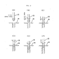
- a tap 1 is positioned by quick feed at a predetermined position in the X - Y plane of a workpiece 2 as shown in Fig. 1(A). Then, positioning of the tap 1 in the Z axis direction is effected by quick feed while driving a spindle in a forward direction as shown in Fig. l(B), after which, as shown in Fig.
- the tap 1 is fed in the direction of the arrow at a feed rate dependent on the revolving speed of the spindle and the lead of a screw while driving the spindle in the forward direction, thus performing screw cutting.
- the rotation and feed of the spindle are stopped.
- inertia of a spindle motor (not shown) is larger than inertia of a feed motor (not shown) and even if stop commands are simultaneously applied to them, they do not stop at the same time but the spindle motor stops after the feed motor stops.
- the tap 1 retains thrust if the spindle rotates and, accordingly, the tap 1 is coupled with the spindle through a tapper, such as tapmatic (not shown) or the like.
- a tapper such as tapmatic (not shown) or the like.
- the spindle is reversed and, at the same time, the tap 1 is fed in the direction of the arrow at a feed rate dependent on the revolving speed of the spindle and the lead of the screw and when the tap 1 gets out of the workpiece 2, the tap 1 is returned by quick feed to a predetermined position as shown in Fig. 1(D).
- the present invention is to overcome the abovesaid defects and has for its object to improve the screw cutting accuracy and simplify the commanding method.
- the tap is held in a manner to be movable in the direction of the spindle; a tapper, which does not transmit the rotation of the spindle to the tap in the case where the amount of movement of the tap exceeds a predetermined range, is engaged with the spindle; and during screw cutting the feed by the feed motor is effected slightly and the screw cutting is carried out by the thrust of the tap itself resulting from the rotation of the spindle. Accordingly, the screw accuracy can be enhanced. Moreover, since the sequence of screw cutting is commanded by one block of command data, the commanding method can be simplified.
- Figs. 1(A) to (E) are diagrams explanatory of the sequence of conventional screw cutting
- Figs. 2(A) to (C) are sectional views of a tool for use in an embodiment of the present invention
- Figs. 3(A) to (F) are diagrams explanatory of the sequence of screw cutting in the embodiment of the present invention
- Fig. 4 is a sectional view showing the state of the tool during cutting
- Fig. 5 is a block diagram illustrating the embodiment of the present invention
- Fig. 6 is a diagram explanatory of the movement of a spindle.
- Figs. 2(a) to (C) are sectional views illustrating, by way of example, the construction of a tool for use in the embodiment of the present invention, Figs. 2(B) and (C) being sectional views taken on the lines a - a' and b - b' in Fig. 2(A), respectively.
- reference numeral 3 indicates a spindle, 4 an arbor, 5 bearings, 6 a washer, 7 a spring, 8 a spline, 9 a notch, 10 a spring, 11 pawls, 12 a holder, and 13 a tap.
- Figs. 2(A), (B) and (C) indicate a spindle, 4 an arbor, 5 bearings, 6 a washer, 7 a spring, 8 a spline, 9 a notch, 10 a spring, 11 pawls, 12 a holder, and 13 a tap.
- FIG. 3(A) to (F) show an example of the sequence of screw cutting using the tool shown in Figs. 2(A) to (C).
- the sequence shwon in Figs. 3(A) to (F) is carried out with a fixed cycle.
- Fig. 4 is a sectional view showing the state of the tool during cutting, the same reference numerals indicating the same parts.
- the tap 13 is positioned by quick feed at a predetermined position in the X - Y plane of a workpiece 14 as shown in Fig. 3(A).
- Fig. 3(B) positioning of the tap 13 in the Z axis direction is effected by quick feed while driving the spindle 3 in the forward direction.
- the rotation of the spindle 3 is transmitted to the tap 13 via the arbor 4, the spline 8 and the holder 12.
- the tap 13 is fed at a feed rate dependent on the revolving speed of the spindle 3 and the lead of the screw while driving the spindle 3 in the forward direction, thereby cutting the screw.
- feed by the feed motor (not shown) is stopped before reaching the bottom of the hole as depicted in Fig. 3(D).
- the spindle 3 is reversed and, at the same time, the tap 13 is fed back to a predetermined position, as shown in Fig. 3(F), at a feed rate dependent on the revolving speed of the spindle and the lead of the screw.
- the rotation of the spindle 3 (Let it be assumed, in this case, that the spindle 3 is being driven in the direction indicated by the arrow c in Fig. 2(C).) is transmitted to the tap 13 for the notch 9 cut in the holder 12 and the pawls 11 meshingly engage with each other; therefore, the screw is not likely to be broken when the tap 13 is pulled out from the workpiece 14.
- Fig. 5 is a block diagram illustrating an example of the numerically-controlled machine tool embodying the screw cutting control system of the present invention.
- Reference character PT indicates a command tape, TR a tape reader, REG a register, DR a decoder, SCC a control circuit, TM a timer, SCU a spindle motor control unit, EPG a feed pulse generator, INP an interpolator, INPX, INPY and I N PZ X-axis, Y-axis and Z-axis units of the interpolator INP, DET and end detector, SS a servo unit of a spindle motor SPM, SVOX, SVOY and SVOZ servo units of X-axis, Y-axis and Z-axis servomotors SX, SY and SZ, SPH a spindle head, TPP a tapper of the construction shown in Fig. 2, TAP a tap, TG a tachometer generator, and
- Command data for putting the control system of the present invention into practice are stored as command data of one block of the following format (A) on an input medium represented by the command tage PT.
- G84 is an identification code indicating that the command data commanding the tap cycle according to the system of the present invention have been recorded in the form of a fixed cycle command
- X is a block end mark.
- numeric data are stored which individually indicate the amount of movement in the X axis, the amount of movement in the Y axis, the amount of movement for cutting feed in the Z axis, the amount of movement for quick feed in the Z axis, the dwell time and the cutting feed rate.
- the cutting feed rate f(mm/min) is computed by the following equation (1) using the revolving speed S 0 (R.P.M.) of the spindle SPD and the lead H 0 (mm/REV) of the tap TAP.
- the dwell time e (sec) is computed by the following equation (2) using the length L (mm) of the screw to be cut in the workpiece W, the revolving speed S 0 (R.P.M.) of the spindle SPD and the head H 0 (mm/REV) of the tap TAP.
- the numeric data a to f punched in the command tage PT are stored in register areas XR, YR, ZR, RR, PR and FR of the register REG respectively corresponding to them.
- a register area SR is stored a revolving speed command value s of the spindle SPD precommanded in a command block immediately preceding the fixed cycle command data (B), or a previous command block.
- the decoder DR Upon decoding the identification code G84 and the block end mark K, the decoder DR provides a signal to the control circuit SCC, by which operations mentioned below in (1)' to (7)' necessary for performing the operations referred to previously in (1) to (7) are carried out under the control of the control circuit SCC.
- (1)' The content of the register area SR of the register REG, that is, the command value s of the spindle revolving speed, is applied to the spindle motor control unit SCU, and the spindle motor control unit SCU supplies the servo unit SS of the spindle motor SPM with a voltage signal proportional to the command value s to drive the spindle motor SP M .
- the revolving speed of the spindle motor SPM is detected by a speed sensor formed by the tachometer generator TG and the detection result is negatively fed back to the servo unit SS of the spindle motor SPM, driving the spindle motor SPM at a speed equal to the command value s.
- the control circuit SCC reads out the numeric values a and b from the register areas XR and YR of the register RES and sets them in the X-axis and Y-axis units INPX and INPY of the interpolator INP, thereby starting pulse distribution in the interpolator INP.
- the feed pulse generator FPG is being supplied with a numeric value F 0 indicating a predetermined quick feed rate and the feed pulse generator FPG yields a pulse train corresponding to the quick feed velocity.
- the interpolator INP effects pulse distribution in the X and Y axes at the same time in synchronism with the pulse train from the feed pulse generator FPG and provides distribution pulses of the X and Y axes to the servo units SVOX and SVOY to rotate the servo motors SX and SY and the feed screws FSX and FSY, performing relative positioning of the tap TAP and the workpiece W in the X-Y plane by quick feed.
- the interpolator INP completes the pulse distributing operation and, upon detection of the end of the distribution pulse sending operation, the end detector DET supplies the control circuit SCC with information to that effect.
- the present invention possesses the advantage that since the tapper transmits the rotation of the spindle tb the tap only while the screw is cut by a mechanically determined amount after stopping the feed during the screw cutting operation, the depth of the screw hole can be made accurate. Moreover, the present invention has the advantage that since the move command in the X-Y plane, the amount of quick feed in the Z-axis direction, the amount of cutting feed in the Z-axis direction, the dwell command value and the cutting feed rate command value can be commanded with one block of command data, the commanding method is very simple.
Landscapes
- Engineering & Computer Science (AREA)
- Human Computer Interaction (AREA)
- Manufacturing & Machinery (AREA)
- Physics & Mathematics (AREA)
- General Physics & Mathematics (AREA)
- Automation & Control Theory (AREA)
- Mechanical Engineering (AREA)
- Numerical Control (AREA)
- Automatic Control Of Machine Tools (AREA)
Applications Claiming Priority (2)
| Application Number | Priority Date | Filing Date | Title |
|---|---|---|---|
| JP55145128A JPS6020134B2 (ja) | 1980-10-17 | 1980-10-17 | ねじ切り制御方式 |
| JP145128/80 | 1980-10-17 |
Publications (3)
| Publication Number | Publication Date |
|---|---|
| EP0062681A1 true EP0062681A1 (de) | 1982-10-20 |
| EP0062681A4 EP0062681A4 (de) | 1985-03-06 |
| EP0062681B1 EP0062681B1 (de) | 1987-05-13 |
Family
ID=15378043
Family Applications (1)
| Application Number | Title | Priority Date | Filing Date |
|---|---|---|---|
| EP81902822A Expired EP0062681B1 (de) | 1980-10-17 | 1981-10-16 | Steuerverfahren zum gewindebohren |
Country Status (5)
| Country | Link |
|---|---|
| US (1) | US4571687A (de) |
| EP (1) | EP0062681B1 (de) |
| JP (1) | JPS6020134B2 (de) |
| DE (1) | DE3176177D1 (de) |
| WO (1) | WO1982001336A1 (de) |
Cited By (1)
| Publication number | Priority date | Publication date | Assignee | Title |
|---|---|---|---|---|
| EP0254768A3 (en) * | 1986-07-28 | 1988-09-14 | Dieter Kuhne | Screw-tapping machine |
Families Citing this family (10)
| Publication number | Priority date | Publication date | Assignee | Title |
|---|---|---|---|---|
| JPS60167731A (ja) * | 1984-02-03 | 1985-08-31 | Fanuc Ltd | タツピング加工方法 |
| JP2510980B2 (ja) * | 1985-10-21 | 1996-06-26 | 株式会社安川電機 | ネジ切削制御方法 |
| JPS63123605A (ja) * | 1986-11-12 | 1988-05-27 | Fanuc Ltd | タツピング加工制御装置 |
| GB8812292D0 (en) * | 1988-05-24 | 1988-06-29 | Black & Decker Inc | Improvements in/relating to power tools |
| JP2581797B2 (ja) * | 1989-04-27 | 1997-02-12 | オ−クマ株式会社 | 同期制御方法及びその装置 |
| JPH087626B2 (ja) * | 1990-03-27 | 1996-01-29 | 株式会社安川電機 | 2つのサーボ系間の追従制御方式 |
| US7003373B2 (en) * | 2002-09-27 | 2006-02-21 | Siemens Aktiengesellschaft | Method and device for numerical control |
| JP4572157B2 (ja) * | 2005-11-01 | 2010-10-27 | 本田技研工業株式会社 | ねじ成形方法及びねじ成形装置 |
| US7650598B2 (en) * | 2006-08-09 | 2010-01-19 | National Tsing Hua University | Method for allocating registers for a processor |
| WO2024214301A1 (ja) * | 2023-04-14 | 2024-10-17 | ファナック株式会社 | 指令生成装置およびコンピュータ読み取り可能な記憶媒体 |
Family Cites Families (8)
| Publication number | Priority date | Publication date | Assignee | Title |
|---|---|---|---|---|
| JPS457595Y1 (de) * | 1966-08-22 | 1970-04-11 | ||
| US3854837A (en) * | 1973-02-23 | 1974-12-17 | Textron Inc | Apparatus and means for performing a method for controlled deep hole drilling |
| SU477794A1 (ru) * | 1973-07-09 | 1975-07-25 | Всесоюзный Научно-Исследовательский Институт Легкого И Текстильного Машиностроения | Патрон дл нарезани резьбы |
| US4079235A (en) * | 1976-12-27 | 1978-03-14 | Mcdonnell Douglas Corporation | Computer numerically controlled threadcutting machine tool |
| JPS5520419Y2 (de) * | 1977-05-30 | 1980-05-16 | ||
| US4096770A (en) * | 1977-06-06 | 1978-06-27 | Cincinnati Milacron Inc. | Method and apparatus for modifying the position of a machine slide to compensate for different following errors |
| CH636787A5 (de) * | 1978-12-04 | 1983-06-30 | Max Hetzel | Elektronisch gesteuerte gewindeschneidmaschine. |
| JPS6044088B2 (ja) * | 1979-09-29 | 1985-10-01 | ブラザー工業株式会社 | 異常検出装置を備えたタツプ盤 |
-
1980
- 1980-10-17 JP JP55145128A patent/JPS6020134B2/ja not_active Expired
-
1981
- 1981-10-16 WO PCT/JP1981/000288 patent/WO1982001336A1/ja not_active Ceased
- 1981-10-16 DE DE8181902822T patent/DE3176177D1/de not_active Expired
- 1981-10-16 EP EP81902822A patent/EP0062681B1/de not_active Expired
- 1981-10-16 US US06/395,081 patent/US4571687A/en not_active Expired - Fee Related
Non-Patent Citations (2)
| Title |
|---|
| No relevant documents have been disclosed. * |
| See also references of WO8201336A1 * |
Cited By (1)
| Publication number | Priority date | Publication date | Assignee | Title |
|---|---|---|---|---|
| EP0254768A3 (en) * | 1986-07-28 | 1988-09-14 | Dieter Kuhne | Screw-tapping machine |
Also Published As
| Publication number | Publication date |
|---|---|
| JPS5771724A (en) | 1982-05-04 |
| WO1982001336A1 (en) | 1982-04-29 |
| EP0062681A4 (de) | 1985-03-06 |
| DE3176177D1 (en) | 1987-06-19 |
| EP0062681B1 (de) | 1987-05-13 |
| JPS6020134B2 (ja) | 1985-05-20 |
| US4571687A (en) | 1986-02-18 |
Similar Documents
| Publication | Publication Date | Title |
|---|---|---|
| US4656405A (en) | Tapping machining method | |
| EP0062681B1 (de) | Steuerverfahren zum gewindebohren | |
| US3854353A (en) | Method and apparatus for performing a threading operation on a rotating workpiece | |
| EP0137857B1 (de) | Numerisches regelverfahren | |
| DE3785827T2 (de) | System zum regeln des zapfens. | |
| US4580225A (en) | Method for producing multiple entry threads | |
| EP0116950B1 (de) | Numerisch gesteuertes Bearbeitungssystem | |
| EP0294486B1 (de) | Gewindekontrollvorrichtung | |
| EP0474882B1 (de) | Numerische steuerung | |
| GB1322108A (en) | Numerical control system for a lathe | |
| EP0356522A1 (de) | Verfahren zur evolventen-interpolation | |
| EP0394459B1 (de) | Vorrichtung zum überwachen der gewindebohroperation | |
| JP2510980B2 (ja) | ネジ切削制御方法 | |
| US3381557A (en) | Method and apparatus for cutting threads | |
| EP0113682B1 (de) | Numerisches Steuerungssystem und Verfahren | |
| KR910007258B1 (ko) | Nc데이터 작성방법 | |
| EP0360242B1 (de) | Numerische Steuerungseinrichtung | |
| EP0070700B1 (de) | Verfahren und Gerät zur Steuerung einer Funkenerosionsmaschine | |
| HK1006044B (en) | Numerical control device | |
| EP0362391A1 (de) | Verfahren zur evolventen-interpolation | |
| DE3854469T2 (de) | Numerische steuerung. | |
| EP0031387B1 (de) | Verfahren und Steuervorrichtung zur Erzielung einer konstanten Schnittgeschwindigkeit | |
| JPH0561651B2 (de) | ||
| JPH0630011B2 (ja) | 数値制御加工再開制御方式 | |
| EP0584370B1 (de) | Verfahren zum Schrauben einer Röhre mit Gewinden unterschiedlicher Hübe auf der Aussen- und Innenseite in ein Objekt |
Legal Events
| Date | Code | Title | Description |
|---|---|---|---|
| PUAI | Public reference made under article 153(3) epc to a published international application that has entered the european phase |
Free format text: ORIGINAL CODE: 0009012 |
|
| 17P | Request for examination filed |
Effective date: 19820617 |
|
| AK | Designated contracting states |
Designated state(s): CH DE FR GB LI |
|
| GRAA | (expected) grant |
Free format text: ORIGINAL CODE: 0009210 |
|
| AK | Designated contracting states |
Kind code of ref document: B1 Designated state(s): CH DE FR GB LI |
|
| REF | Corresponds to: |
Ref document number: 3176177 Country of ref document: DE Date of ref document: 19870619 |
|
| ET | Fr: translation filed | ||
| PG25 | Lapsed in a contracting state [announced via postgrant information from national office to epo] |
Ref country code: LI Effective date: 19871031 Ref country code: CH Effective date: 19871031 |
|
| PLBE | No opposition filed within time limit |
Free format text: ORIGINAL CODE: 0009261 |
|
| STAA | Information on the status of an ep patent application or granted ep patent |
Free format text: STATUS: NO OPPOSITION FILED WITHIN TIME LIMIT |
|
| 26N | No opposition filed | ||
| GBPC | Gb: european patent ceased through non-payment of renewal fee | ||
| REG | Reference to a national code |
Ref country code: CH Ref legal event code: PL |
|
| PG25 | Lapsed in a contracting state [announced via postgrant information from national office to epo] |
Ref country code: DE Effective date: 19880701 |
|
| PG25 | Lapsed in a contracting state [announced via postgrant information from national office to epo] |
Ref country code: GB Effective date: 19881121 |
|
| PG25 | Lapsed in a contracting state [announced via postgrant information from national office to epo] |
Ref country code: FR Free format text: LAPSE BECAUSE OF NON-PAYMENT OF DUE FEES Effective date: 19890630 |
|
| REG | Reference to a national code |
Ref country code: FR Ref legal event code: ST |