EP0062683A1 - Systeme de commande numerique - Google Patents
Systeme de commande numerique Download PDFInfo
- Publication number
- EP0062683A1 EP0062683A1 EP81902861A EP81902861A EP0062683A1 EP 0062683 A1 EP0062683 A1 EP 0062683A1 EP 81902861 A EP81902861 A EP 81902861A EP 81902861 A EP81902861 A EP 81902861A EP 0062683 A1 EP0062683 A1 EP 0062683A1
- Authority
- EP
- European Patent Office
- Prior art keywords
- tool
- workpiece
- numerical control
- rotation
- center
- Prior art date
- Legal status (The legal status is an assumption and is not a legal conclusion. Google has not performed a legal analysis and makes no representation as to the accuracy of the status listed.)
- Granted
Links
Images
Classifications
-
- G—PHYSICS
- G05—CONTROLLING; REGULATING
- G05B—CONTROL OR REGULATING SYSTEMS IN GENERAL; FUNCTIONAL ELEMENTS OF SUCH SYSTEMS; MONITORING OR TESTING ARRANGEMENTS FOR SUCH SYSTEMS OR ELEMENTS
- G05B19/00—Program-control systems
- G05B19/02—Program-control systems electric
- G05B19/18—Numerical control [NC], i.e. automatically operating machines, in particular machine tools, e.g. in a manufacturing environment, so as to execute positioning, movement or co-ordinated operations by means of program data in numerical form
- G05B19/41—Numerical control [NC], i.e. automatically operating machines, in particular machine tools, e.g. in a manufacturing environment, so as to execute positioning, movement or co-ordinated operations by means of program data in numerical form characterised by interpolation, e.g. the computation of intermediate points between programmed end points to define the path to be followed and the rate of travel along that path
-
- G—PHYSICS
- G05—CONTROLLING; REGULATING
- G05B—CONTROL OR REGULATING SYSTEMS IN GENERAL; FUNCTIONAL ELEMENTS OF SUCH SYSTEMS; MONITORING OR TESTING ARRANGEMENTS FOR SUCH SYSTEMS OR ELEMENTS
- G05B2219/00—Program-control systems
- G05B2219/30—Nc systems
- G05B2219/35—Nc in input of data, input till input file format
- G05B2219/35525—Use same data for different operations, coarse and fine, cutting and grinding
-
- G—PHYSICS
- G05—CONTROLLING; REGULATING
- G05B—CONTROL OR REGULATING SYSTEMS IN GENERAL; FUNCTIONAL ELEMENTS OF SUCH SYSTEMS; MONITORING OR TESTING ARRANGEMENTS FOR SUCH SYSTEMS OR ELEMENTS
- G05B2219/00—Program-control systems
- G05B2219/30—Nc systems
- G05B2219/36—Nc in input of data, input key till input tape
- G05B2219/36573—X, y, z and tooloffset values or direction values
-
- G—PHYSICS
- G05—CONTROLLING; REGULATING
- G05B—CONTROL OR REGULATING SYSTEMS IN GENERAL; FUNCTIONAL ELEMENTS OF SUCH SYSTEMS; MONITORING OR TESTING ARRANGEMENTS FOR SUCH SYSTEMS OR ELEMENTS
- G05B2219/00—Program-control systems
- G05B2219/30—Nc systems
- G05B2219/49—Nc machine tool, till multiple
- G05B2219/49243—5-D
-
- G—PHYSICS
- G05—CONTROLLING; REGULATING
- G05B—CONTROL OR REGULATING SYSTEMS IN GENERAL; FUNCTIONAL ELEMENTS OF SUCH SYSTEMS; MONITORING OR TESTING ARRANGEMENTS FOR SUCH SYSTEMS OR ELEMENTS
- G05B2219/00—Program-control systems
- G05B2219/30—Nc systems
- G05B2219/50—Machine tool, machine tool null till machine tool work handling
- G05B2219/50289—Tool offset general
-
- G—PHYSICS
- G05—CONTROLLING; REGULATING
- G05B—CONTROL OR REGULATING SYSTEMS IN GENERAL; FUNCTIONAL ELEMENTS OF SUCH SYSTEMS; MONITORING OR TESTING ARRANGEMENTS FOR SUCH SYSTEMS OR ELEMENTS
- G05B2219/00—Program-control systems
- G05B2219/30—Nc systems
- G05B2219/50—Machine tool, machine tool null till machine tool work handling
- G05B2219/50295—Tool offset by manual input by switches
-
- G—PHYSICS
- G05—CONTROLLING; REGULATING
- G05B—CONTROL OR REGULATING SYSTEMS IN GENERAL; FUNCTIONAL ELEMENTS OF SUCH SYSTEMS; MONITORING OR TESTING ARRANGEMENTS FOR SUCH SYSTEMS OR ELEMENTS
- G05B2219/00—Program-control systems
- G05B2219/30—Nc systems
- G05B2219/50—Machine tool, machine tool null till machine tool work handling
- G05B2219/50336—Tool, probe offset for curves, surfaces, contouring
-
- G—PHYSICS
- G05—CONTROLLING; REGULATING
- G05B—CONTROL OR REGULATING SYSTEMS IN GENERAL; FUNCTIONAL ELEMENTS OF SUCH SYSTEMS; MONITORING OR TESTING ARRANGEMENTS FOR SUCH SYSTEMS OR ELEMENTS
- G05B2219/00—Program-control systems
- G05B2219/30—Nc systems
- G05B2219/50—Machine tool, machine tool null till machine tool work handling
- G05B2219/50356—Tool perpendicular, normal to 3-D surface
Definitions
- the present invention relates to a numerical control system, and more particularly to a numerical control system which is suitably applied to a numerical control machine tool wherein a tool is moved or rotated in the directions of the three X, Y and Z(orthogonal coordinate system) axes and in the directions of the two B and C (spherical coordinate system) axes so as to subject a workpiece to three-dimensional machining.
- a tool or a table is rotated in the vertical rotational direction (B-axial direction) and the horizontal rotational direction (C-axial direction) so as to control the axial direction of the tool relative to a workpiece or the table (this axial direction being the tool axis direction), and it is also moved in the directions of the three X, Y and Z axes so as to subject the workpiece to a desired machining operation.
- the position Q(x, y, z) of the center of rotation of the tool and the position of the tool axis direction of the tool, in other words, the position (b, c) of a rotational angle are entered from a command tape as NC command data.
- a pulse distribution circuit within the NC system executes pulse distribution computations, whereupon it rotates the tool in the B- and C-axial directions so as to bring the axial direction of the tool into agreement with a commanded tool axis direction, for example, the normal direction of the workpiece and also moves a tool holder as well as the tool in the X, Y and Z directions so as to subject the workpiece to the programmed three-dimensional machining.
- the command tape for the 5-axis control has hitherto been prepared as follows: First, the coordinates (X, Y, Z) of the position P of the front end of the tool as found by a main processor, the vector (I, J, K) of the tool axis direction at the front end position (for example, the normal to the workpiece) as similarly found by the main processor, and a length A from the position Q of the center of rotation of the tool to the position P of the front end of the tool, are input to a post-processor, The position (x, y, z) of the center of rotation of the tool and the position (b, c) of the tool axis are found by the post-processor. Lastly, these values x, y, z, b and c are punched in the tape as the command data, to obtain the predetermined command tape.
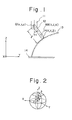
- Figures 1 and 2 are explanatory views for explaining the 5-axis control in the case where a table and workpiece are fixed and where a tool is moved in the directions of the three X, Y and Z (orthogonal coordinate system) axes and in the directions of the two of B and C (spherical coordinate system) axes.
- numeral 11 designates a tool holder which supports a tool and which is driven in the three axial directions of the X-, Y- and Z-axes by servomotors not shown, and numeral 12 the tool, the front end position P(X, Y, Z) of which is rotated in the B- and C-axial directions about the position Q(x, y, z) of the center of rotation.
- the B-axial and C-axial directions are the vertical rotational direction and horizontal rotational direction, respectively ( Figure 2), and the spherical coordinate system is formed by a rotational angle b along the B-axis, a rotational angle c along the C-axis and a tool length t.
- Numeral 13 indicates a workpiece, and numeral 14 a table on which the workpiece 13 is placed.
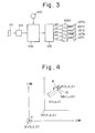
- Figure 3 is a circuit block diagram showing an embodiment of the present invention.
- numeral 101 indicates a command tape in or on which the position P(X, Y, Z) of the front end of the tool 12 ( Figure 1) and the vector NB (I, J, K) of the tool axis direction of the tool, as well as a feed rate command, a spindle speed command, etc. are punched or recorded, numeral 102 a tape reader, and numeral 103 an input device such as a dial or digital switch, which enters the length k from the center of rotation Q of the tool to the front end position P of the tool.
- Numeral 104 indicates a movement data calculation circuit, which calculates the orthogonal coordinate values (x, y, z) of the rotational center Q of the tool and the spherical coordinate values (b, c) indicative of the position of the rotational angle of the tool 12 from the coordinates (X, Y, Z) of the front end position of the tool, the vector (I, J, K) of the tool axis direction and the tool length l in conformity with Equations(1) - (5).
- Equations (4) and (5) are the equations of transformation from the orthogonal coordinate system into the spherical coordinate system. More specifically, imagining a orthogonal coordinate system and a spherical coordinate system the origins of which coincide with the center of rotation Q of the tool 12 as shown in Figure 2, the tool of length l is rotated by b in the B-axial direction (the vertical rotational direction) and by c in the C-axial direction (the horizontal rotational direction). Then, the orthogonal coordinates (I 0 , J 0 , K 0 ) of the front end of the tool are expressed by: When b and c are found from these equations (6) - (8), they become Equations (4) and (5).
- Numeral 105 represents a pulse distribution circuit, which executes pulse distribution computations on the basis of x, y, z, -b and c obtained by the movement data calculation circuit 104 and which delivers distributed pulses XP, YP, ZP, BP and CP for the respective axes.
- Shown at 106X, 106Y, 106Z, 106B and 106C are known servo circuits, which receive the distributed pulses XP, YP, ZP, BP and CP and rotate servomotors, 107X, 107Y, 107Z, 107B and 107C, respectively.
- the movement data calculation circuit 104 executes the calculations of Equations (1) to (5) by the use of these values (X, Y, Z) and (I, J, K) and the length l from the rotational center of the tool to the front end position thereof set by the dial or the like 103 beforehand, to find the Orthogonal coordinate values ( x , y, z ) of the position Q of the rotational center of the tool and the spherical coordinate values (b, c) indicative of the position of the rotational angle of the tool, and it applies these coordinate values to the pulse distribution circuit 105.
- the pulse distribution circuit 105 When supplied with x, y, z, b and c, the pulse distribution circuit 105 computes movement values (incremental values) in the respective axial directions, on the basis of which known DDAs (Digital Differential Analyzers) or the like execute pulse distribution computations and deliver the distributed pulses XP, YP, ZP, BP and CP of the respective axes. These distributed pulses of the respective axes are applied to the servo circuits 106X - 106C, which rotate and drive the corresponding servomotors 107X - 107C under well-known servo control so as to move the tool or table as programmed and to subject the workpiece to desired machining.
- DDAs Digital Differential Analyzers
- the present invention has been described in detail in conjunction with the drawings, but it is not restricted to the embodiment.
- the invention is also applicable to a case where, letting another rotational direction be an A-axial direction, the tool is rotated in the A- and B-axial directions or the A- and C-axial directions, or a case where the tool is rotated in any desired uniaxial direction.
- the invention is also applicable to a case where the workpiece is rotated or to a case where both the tool and the workpiece are rotated in axial directions different from each other.
- Equations (1) - (5) differ.
- the equations of transformation when rotating the tool in the B-axial direction and when rotating the table in the C-axial direction about the Z-axis become the following equations.
- the rotational center 0 1 of the table is taken as the absolute origin (O, O, O)
- command tape paper tape, magnetic tape
- present invention does not exclude any other input medium.
Landscapes
- Engineering & Computer Science (AREA)
- Computing Systems (AREA)
- Theoretical Computer Science (AREA)
- Human Computer Interaction (AREA)
- Manufacturing & Machinery (AREA)
- Physics & Mathematics (AREA)
- General Physics & Mathematics (AREA)
- Automation & Control Theory (AREA)
- Numerical Control (AREA)
Abstract
Applications Claiming Priority (2)
| Application Number | Priority Date | Filing Date | Title |
|---|---|---|---|
| JP148759/80 | 1980-10-23 | ||
| JP55148759A JPS5773410A (en) | 1980-10-23 | 1980-10-23 | Numerical control system |
Publications (3)
| Publication Number | Publication Date |
|---|---|
| EP0062683A1 true EP0062683A1 (fr) | 1982-10-20 |
| EP0062683A4 EP0062683A4 (fr) | 1985-06-26 |
| EP0062683B1 EP0062683B1 (fr) | 1989-08-02 |
Family
ID=15459997
Family Applications (1)
| Application Number | Title | Priority Date | Filing Date |
|---|---|---|---|
| EP81902861A Expired EP0062683B1 (fr) | 1980-10-23 | 1981-10-23 | Systeme de commande numerique |
Country Status (5)
| Country | Link |
|---|---|
| US (1) | US4516211A (fr) |
| EP (1) | EP0062683B1 (fr) |
| JP (1) | JPS5773410A (fr) |
| DE (1) | DE3177081D1 (fr) |
| WO (1) | WO1982001599A1 (fr) |
Cited By (4)
| Publication number | Priority date | Publication date | Assignee | Title |
|---|---|---|---|---|
| FR2556627A1 (fr) * | 1983-12-16 | 1985-06-21 | Honda Motor Co Ltd | Perceuse |
| EP0075030A4 (fr) * | 1981-04-04 | 1985-09-16 | Fanuc Ltd | Procede d'usinage a commande numerique. |
| EP0188626A4 (fr) * | 1984-07-16 | 1988-12-12 | Fanuc Ltd | Systeme de correction de la position d'un outil. |
| EP0796704A4 (fr) * | 1995-09-06 | 1997-10-15 |
Families Citing this family (7)
| Publication number | Priority date | Publication date | Assignee | Title |
|---|---|---|---|---|
| JPS57194855A (en) * | 1981-05-27 | 1982-11-30 | Fanuc Ltd | Numerical control system |
| JPS6055412A (ja) * | 1983-09-06 | 1985-03-30 | Fanuc Ltd | Νcデ−タ作成方法 |
| JPS6085812A (ja) * | 1983-10-15 | 1985-05-15 | Fanuc Ltd | 領域加工におけるアプロ−チ方法 |
| JPS61190607A (ja) * | 1985-02-18 | 1986-08-25 | Toyoda Mach Works Ltd | 異常停止機能を備えた数値制御工作機械 |
| DE3519132A1 (de) * | 1985-05-29 | 1986-12-04 | Hermann Pfauter GmbH & Co, 7140 Ludwigsburg | Verfahren zur messung und/oder regelung der lage eines bewegten, vorzugsweise drehenden bezugselementes einer werkzeugmaschine, vorzugsweise einer verzahnmaschine, abhaengig von der lage eines weiteren bewegten, vorzugsweise drehenden hauptfuehrungselementes und vorrichtung zur durchfuehrung eines solchen verfahrens |
| JPH08383B2 (ja) * | 1987-08-04 | 1996-01-10 | 株式会社明電舎 | ロボットの制御装置 |
| JP3599800B2 (ja) * | 1994-10-24 | 2004-12-08 | 東芝機械株式会社 | 数値制御工作機械の主軸法線方向制御方法 |
Family Cites Families (11)
| Publication number | Priority date | Publication date | Assignee | Title |
|---|---|---|---|---|
| GB215065A (en) * | 1923-01-30 | 1924-04-30 | George Norman Blanchard | Automatically-controlled pressure feed for liquid hydrocarbon burners |
| GB843468A (en) * | 1956-02-02 | 1960-08-04 | Inductosyn Ltd | An automatic machine control system |
| CH408168A (de) * | 1961-03-13 | 1966-02-28 | Fuji Tsushinki Seizo Kk | Numerische Kontrollvorrichtung für eine Werkzeugmaschine |
| SE317535B (fr) * | 1961-03-13 | 1969-11-17 | Fuji Tsushinki Seizo K K | |
| US3633011A (en) * | 1968-08-29 | 1972-01-04 | Ibm | Method and apparatus for precisely contouring a workpiece imprecisely positioned on a supporting fixture |
| US3665280A (en) * | 1969-08-22 | 1972-05-23 | Stewart Warner Corp | Zero offset numerical servo machine control system |
| JPS49101790A (fr) * | 1973-02-02 | 1974-09-26 | ||
| US3866027A (en) * | 1973-05-09 | 1975-02-11 | Bendix Corp | Digital tool size compensation for numerical control |
| JPS50148779A (fr) * | 1974-05-21 | 1975-11-28 | ||
| US4162527A (en) * | 1977-07-29 | 1979-07-24 | Hamill Company, Inc. | Numerically controlled machine tool system with programmable tool offset |
| DE2846170C2 (de) * | 1978-10-24 | 1986-06-12 | Dr. Johannes Heidenhain Gmbh, 8225 Traunreut | Numerische Steuerungseinrichtung |
-
1980
- 1980-10-23 JP JP55148759A patent/JPS5773410A/ja active Pending
-
1981
- 1981-10-23 DE DE8181902861T patent/DE3177081D1/de not_active Expired
- 1981-10-23 EP EP81902861A patent/EP0062683B1/fr not_active Expired
- 1981-10-23 WO PCT/JP1981/000296 patent/WO1982001599A1/fr not_active Ceased
- 1981-10-23 US US06/394,914 patent/US4516211A/en not_active Expired - Fee Related
Cited By (5)
| Publication number | Priority date | Publication date | Assignee | Title |
|---|---|---|---|---|
| EP0075030A4 (fr) * | 1981-04-04 | 1985-09-16 | Fanuc Ltd | Procede d'usinage a commande numerique. |
| FR2556627A1 (fr) * | 1983-12-16 | 1985-06-21 | Honda Motor Co Ltd | Perceuse |
| EP0188626A4 (fr) * | 1984-07-16 | 1988-12-12 | Fanuc Ltd | Systeme de correction de la position d'un outil. |
| EP0796704A4 (fr) * | 1995-09-06 | 1997-10-15 | ||
| US6414711B2 (en) | 1995-09-06 | 2002-07-02 | Fanuc Ltd. | Apparatus for correcting movement path of a robot and a method therefor |
Also Published As
| Publication number | Publication date |
|---|---|
| DE3177081D1 (en) | 1989-09-07 |
| EP0062683B1 (fr) | 1989-08-02 |
| US4516211A (en) | 1985-05-07 |
| WO1982001599A1 (fr) | 1982-05-13 |
| JPS5773410A (en) | 1982-05-08 |
| EP0062683A4 (fr) | 1985-06-26 |
Similar Documents
| Publication | Publication Date | Title |
|---|---|---|
| US4788481A (en) | Numerical control apparatus | |
| US4692856A (en) | Position control of multiple tools based on elapsed time of tool operation | |
| US6019554A (en) | Method and system for computer assisted manual machine tool control | |
| US5563484A (en) | Three-dimensional cutter compensation system | |
| EP1235125A2 (fr) | Appareil de commande de découpe pour une machine de coupe, machine de coupe et méthode de découpage | |
| EP0063615B1 (fr) | Procede de commande numerique | |
| EP0062683B1 (fr) | Systeme de commande numerique | |
| EP0063606B1 (fr) | Systeme de commande numerique | |
| EP0356522A1 (fr) | Procede d'interpolation de developpante | |
| EP0077177B1 (fr) | Méthode et dispositif pour la commande numérique | |
| EP0509103A1 (fr) | Procede de transformation des coordonnees d'un laser tridimensionnel | |
| US4862380A (en) | Numerical control unit | |
| US4811235A (en) | Coordinate interpolation in numerical control apparatus | |
| EP0362391B1 (fr) | Procede d'interpolation de developpante | |
| US3178717A (en) | Method and apparatus for producing machine-tool-controlling magnetic tapes directly from drawings | |
| JPS6094255A (ja) | 工作機械の加工方法 | |
| US4766546A (en) | Numerically controlled apparatus including functions of synchronous-simultaneous transaction and independent-simultaneous translation | |
| EP0160705A1 (fr) | Procede d'usinage pour machines-outils | |
| JP3049627B2 (ja) | 複合工作機械 | |
| JPH05108134A (ja) | 主軸の割出対応の座標変換方法 | |
| EP0380685A1 (fr) | Systeme de commande numerique | |
| JPS6168606A (ja) | 数値制御装置 | |
| KR830001478B1 (ko) | 수치 제어공작기계에 있어서 공구선택 방법 | |
| JPH07334223A (ja) | 工具軸姿勢制御方式 | |
| JPH03109606A (ja) | 工具補正方式 |
Legal Events
| Date | Code | Title | Description |
|---|---|---|---|
| PUAI | Public reference made under article 153(3) epc to a published international application that has entered the european phase |
Free format text: ORIGINAL CODE: 0009012 |
|
| 17P | Request for examination filed |
Effective date: 19820623 |
|
| AK | Designated contracting states |
Designated state(s): DE FR GB |
|
| 17Q | First examination report despatched |
Effective date: 19870429 |
|
| GRAA | (expected) grant |
Free format text: ORIGINAL CODE: 0009210 |
|
| AK | Designated contracting states |
Kind code of ref document: B1 Designated state(s): DE FR GB |
|
| REF | Corresponds to: |
Ref document number: 3177081 Country of ref document: DE Date of ref document: 19890907 |
|
| ET | Fr: translation filed | ||
| PLBE | No opposition filed within time limit |
Free format text: ORIGINAL CODE: 0009261 |
|
| STAA | Information on the status of an ep patent application or granted ep patent |
Free format text: STATUS: NO OPPOSITION FILED WITHIN TIME LIMIT |
|
| 26N | No opposition filed | ||
| PGFP | Annual fee paid to national office [announced via postgrant information from national office to epo] |
Ref country code: FR Payment date: 19911003 Year of fee payment: 11 |
|
| PGFP | Annual fee paid to national office [announced via postgrant information from national office to epo] |
Ref country code: DE Payment date: 19911008 Year of fee payment: 11 |
|
| PGFP | Annual fee paid to national office [announced via postgrant information from national office to epo] |
Ref country code: GB Payment date: 19911011 Year of fee payment: 11 |
|
| PG25 | Lapsed in a contracting state [announced via postgrant information from national office to epo] |
Ref country code: GB Effective date: 19921023 |
|
| GBPC | Gb: european patent ceased through non-payment of renewal fee |
Effective date: 19921023 |
|
| PG25 | Lapsed in a contracting state [announced via postgrant information from national office to epo] |
Ref country code: FR Effective date: 19930630 |
|
| PG25 | Lapsed in a contracting state [announced via postgrant information from national office to epo] |
Ref country code: DE Effective date: 19930701 |
|
| REG | Reference to a national code |
Ref country code: FR Ref legal event code: ST |