EP0062690B1 - Fixation de fils pour clôtures - Google Patents
Fixation de fils pour clôtures Download PDFInfo
- Publication number
- EP0062690B1 EP0062690B1 EP81102889A EP81102889A EP0062690B1 EP 0062690 B1 EP0062690 B1 EP 0062690B1 EP 81102889 A EP81102889 A EP 81102889A EP 81102889 A EP81102889 A EP 81102889A EP 0062690 B1 EP0062690 B1 EP 0062690B1
- Authority
- EP
- European Patent Office
- Prior art keywords
- passage
- wire fixing
- wire
- fixing means
- head
- Prior art date
- Legal status (The legal status is an assumption and is not a legal conclusion. Google has not performed a legal analysis and makes no representation as to the accuracy of the status listed.)
- Expired
Links
- 238000003780 insertion Methods 0.000 description 13
- 230000037431 insertion Effects 0.000 description 13
Images
Classifications
-
- E—FIXED CONSTRUCTIONS
- E04—BUILDING
- E04H—BUILDINGS OR LIKE STRUCTURES FOR PARTICULAR PURPOSES; SWIMMING OR SPLASH BATHS OR POOLS; MASTS; FENCING; TENTS OR CANOPIES, IN GENERAL
- E04H17/00—Fencing, e.g. fences, enclosures, corrals
- E04H17/02—Wire fencing, e.g. made of wire mesh
- E04H17/10—Wire fencing, e.g. made of wire mesh characterised by the way of connecting wire to posts; Droppers
- E04H17/12—Wire fencing, e.g. made of wire mesh characterised by the way of connecting wire to posts; Droppers the wire being placed in slots, grooves, or the like
-
- E—FIXED CONSTRUCTIONS
- E04—BUILDING
- E04H—BUILDINGS OR LIKE STRUCTURES FOR PARTICULAR PURPOSES; SWIMMING OR SPLASH BATHS OR POOLS; MASTS; FENCING; TENTS OR CANOPIES, IN GENERAL
- E04H17/00—Fencing, e.g. fences, enclosures, corrals
- E04H17/02—Wire fencing, e.g. made of wire mesh
- E04H17/10—Wire fencing, e.g. made of wire mesh characterised by the way of connecting wire to posts; Droppers
- E04H17/124—Wire fencing, e.g. made of wire mesh characterised by the way of connecting wire to posts; Droppers connecting by one or more clamps, clips, screws, wedges or ties
Definitions
- the invention relates to a wire holding device for fences with the features listed in the preamble of the claim.
- a wire holder of the type mentioned is known from DE-U 7 239 951.
- the spreader pin has a conical widening on the head side.
- the widening of the expanding pin according to the prior art is intended to have a clamping effect on the tensioning wire according to FIGS. 3 and 4. This widened the passage of the wire holder. This widening thus contributes to the load on the wire holder and, in the worst case, can tear the wire holder apart.
- the object of the invention is to support the wall of the wire holder in order thereby to prevent the wall from breaking off or breaking out.
- This design of the expansion pin with a head provides extensive support for the outside of the wire holder and the wall in question of the insertion slot. This avoids the risk that this wall can break out, for example in the case of sudden loads, large temperature differences and the like.
- the concave design of the underside of the head ensures that the edge of the head of the expansion pin lies precisely against the wall of the insertion slot.
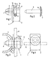
- the wire holder 1 comprises an approximately right-angled body 2 and a spreader pin 3.
- a concave side surface 4 is intended for contact with a post 5.
- a passage 6 extends through the expansion spigot 3 and the entire body 2.
- the expansion spigot 3 has a longitudinal slot 7.
- a spreader pin 8 can be inserted and driven into the passage 6.
- the expansion pin 8 ' is shown in dash-dot lines.
- the expansion pin 3 is expanded like a dowel and, in the installed state according to FIG. 3, ensures that the wire holder 1 is securely held on the post 5.
- the expansion pin 8 has a wide head 9, the head underside 10 of which faces the shaft is concave.
- An insertion slot 11 is formed in the body 2 and, based on the installed state of the wire holder according to FIG. 1, extends from the top and cuts through the passage 6.
- the insertion slot 11 extends approximately around the thickness of the wire 12 to be held beyond the passage.
- the insertion slot 11 is delimited by walls 13 and 14 of the body. There is a barb-like locking tongue 15 on the front side of the insertion slot 11.
- the wire 12 is accommodated in the foot part of the insertion slot, that is to say below the passage 6.
- the expansion pin 8 can be inserted into the insertion slot 6 or pushed in slightly.
- the all-round rimmed passage, which surrounds the wire 12 is formed by the expansion pin 8 ′ drawn in dash-dotted lines in FIG. 1 within the foot part of the insertion slot 11.
- the wire 12 is already held in the foot part of the insertion slot 11 at this stage of the assembly, so that the wire holder 1 can no longer be detached from the wire 12.
- the expansion pin 3 is inserted into a hole 16 in the post 5.
- the spreader pin 8 is driven into the passage 6, so that the spreader pin 3 is thereby spread and the wire holder 1 is fixed to the post 5. Since the shaft of the spreader pin 8 is straight, the spreader pin 8 can be driven into the passage 6 in the usual way without special measures for alignment being required.
- the front edge of the underside of the head 10 of the spreading pin 8 lies over a large area on the outside of the wall 14 of the insertion slot 11.
- the diameter of the head 9 corresponds approximately to the transverse dimension of the wall 14 or the body 2, as can be seen in particular from FIG. 4.
Landscapes
- Engineering & Computer Science (AREA)
- Architecture (AREA)
- Civil Engineering (AREA)
- Structural Engineering (AREA)
- Fencing (AREA)
- Supports For Plants (AREA)
- Supports For Pipes And Cables (AREA)
Claims (1)
- Fixation de fils pour clôtures, comprenant un élément de maintien de fil (1), sur le corps (2) duquel se trouve un tenon expansible (3) qui sert à entrer en prise dans un trou (16) d'un piquet (5) et qui est traversé par un passage (6), et dans le corps (2) duquel une fente d'enfoncement (11) est agencée dans un plan perpendiculaire à l'axe du passage (6) et, en partant de la face supérieure du corps (2), passe au-delà du passage (6) approximativement de l'épaisseur du fil à maintenir (12), une goupille d'expansion (8) présentant un élargissement du côté extrémité étant prévue pour être enfoncée dans le passage (6), caractérisée en ce que l'élargissement est réalisé sous la forme d'une tête (9) dont le diamètre correspond à la dimension transversale du corps (2) et dont la face inférieure (10), qui est en appui sur le corps (2) de l'élément de maintien de fil (1), est réalisée sous une forme concave.
Priority Applications (3)
| Application Number | Priority Date | Filing Date | Title |
|---|---|---|---|
| AT81102889T ATE14469T1 (de) | 1981-04-15 | 1981-04-15 | Drahthaltevorrichtung fuer zaeune. |
| DE8181102889T DE3171461D1 (en) | 1981-04-15 | 1981-04-15 | Wire fixing for fences |
| EP81102889A EP0062690B1 (fr) | 1981-04-15 | 1981-04-15 | Fixation de fils pour clôtures |
Applications Claiming Priority (1)
| Application Number | Priority Date | Filing Date | Title |
|---|---|---|---|
| EP81102889A EP0062690B1 (fr) | 1981-04-15 | 1981-04-15 | Fixation de fils pour clôtures |
Publications (2)
| Publication Number | Publication Date |
|---|---|
| EP0062690A1 EP0062690A1 (fr) | 1982-10-20 |
| EP0062690B1 true EP0062690B1 (fr) | 1985-07-24 |
Family
ID=8187662
Family Applications (1)
| Application Number | Title | Priority Date | Filing Date |
|---|---|---|---|
| EP81102889A Expired EP0062690B1 (fr) | 1981-04-15 | 1981-04-15 | Fixation de fils pour clôtures |
Country Status (3)
| Country | Link |
|---|---|
| EP (1) | EP0062690B1 (fr) |
| AT (1) | ATE14469T1 (fr) |
| DE (1) | DE3171461D1 (fr) |
Families Citing this family (11)
| Publication number | Priority date | Publication date | Assignee | Title |
|---|---|---|---|---|
| NZ208485A (en) * | 1984-06-13 | 1986-06-11 | Gallagher Electronics Ltd | Fence wire insulator screw-clamped to standard received in slot |
| DE3809916C1 (fr) * | 1988-03-24 | 1989-06-29 | Klaus-Dieter 4050 Moenchengladbach De Bethke | |
| US5170299A (en) * | 1990-08-17 | 1992-12-08 | Quantum Corporation | Edge servo for disk drive head positioner |
| SE501059C2 (sv) * | 1992-03-27 | 1994-10-31 | Lars Lilja | Fästorgan för fastsättning av t ex nät eller lina vid en bärare |
| ATE246298T1 (de) * | 1998-02-20 | 2003-08-15 | Alberts Gmbh & Co Kg G | Drahthalter für einem nutzaunpfahl |
| LU90574B1 (en) * | 2000-05-04 | 2001-11-05 | Trefil Arbed Bissen S A | System for fixing fencing material to a fence post |
| US6866251B2 (en) * | 2002-05-28 | 2005-03-15 | Lars Rosaen | Fencing system |
| US7500654B2 (en) | 2002-05-28 | 2009-03-10 | Lars Rosaen | Fencing system |
| GB2411432A (en) * | 2004-02-28 | 2005-08-31 | Advanced Bolting Solutions Ltd | Fastener for linear elements comprising expandable boss |
| RU2489612C1 (ru) * | 2011-12-26 | 2013-08-10 | Владимир Павлович Акимов | Устройство для монтажа протяженных элементов |
| FR3006355B1 (fr) * | 2013-05-29 | 2015-05-15 | Alto Production | Dispositif de fixation de panneau grillage sur un poteau, en vue de la realisation d'un element de fermeture, tel qu'une cloture, element de fermeture obtenu |
Family Cites Families (2)
| Publication number | Priority date | Publication date | Assignee | Title |
|---|---|---|---|---|
| DE7239951U (de) * | 1973-02-15 | Hoesch Werke Ag | Spanndrahthalter mit Spreizstift | |
| DE7723362U1 (de) * | 1977-07-27 | 1977-11-03 | Konrad Kraus Metallwaren Gmbh & Co Kg, 5063 Overath | Drahthalter fuer zaunabspanndraehte |
-
1981
- 1981-04-15 EP EP81102889A patent/EP0062690B1/fr not_active Expired
- 1981-04-15 DE DE8181102889T patent/DE3171461D1/de not_active Expired
- 1981-04-15 AT AT81102889T patent/ATE14469T1/de not_active IP Right Cessation
Also Published As
| Publication number | Publication date |
|---|---|
| ATE14469T1 (de) | 1985-08-15 |
| EP0062690A1 (fr) | 1982-10-20 |
| DE3171461D1 (en) | 1985-08-29 |
Similar Documents
| Publication | Publication Date | Title |
|---|---|---|
| EP0062690B1 (fr) | Fixation de fils pour clôtures | |
| EP2013493A1 (fr) | Dispositif de fixation | |
| DE2913090A1 (de) | Befestigungselement mit ankerbolzen und spreizkeil | |
| EP0019782A2 (fr) | Cheville métallique creuse | |
| DE2442414A1 (de) | Kabelschelle | |
| EP0145886B1 (fr) | Clou à expansion | |
| EP0038494B1 (fr) | Support de contact | |
| DE19918782A1 (de) | Befestigungselement zur Befestigung von Isolierelementen | |
| DE3144803C1 (de) | Rohrschelle zum Befestigen einer Fußbodenheizungsrohrleitung auf einer Dämmschicht | |
| DE19632469C2 (de) | Nagel mit aufspreizbaren Beinen | |
| EP0034346A1 (fr) | Dispositif de fixation pour fixer des revêtements, listeaux ou analogues sur un mur au moyen d'une cheville à tête de serrage en matière plastique | |
| DE102006019256A1 (de) | Befestigungsvorrichtung | |
| DE3740563A1 (de) | Schiene fuer haengedecken | |
| DE3817512A1 (de) | Befestigungselement mit spreizhuelse | |
| DE3620573A1 (de) | Vorrichtung zum befestigen eines gegenstandes an einer wand oder dgl. | |
| DE2611236A1 (de) | Lochplattenverbinder als stahlblech fuer holzbalken oder kanthoelzer im holzbau | |
| DE3941097C1 (en) | Cable channel or tray support - has coupling element fixable from above in form of shaft fitting selectable slots and with projection to act like hook | |
| DE29510606U1 (de) | Befestigungselement zum Anbringen langgestreckter Gegenstände an einer Wand | |
| EP0334183B1 (fr) | Support en plastique pour fil métallique | |
| EP0286706A1 (fr) | Cheville | |
| DE10043330A1 (de) | Wandhalter für Verkleidungstafeln, insbesondere Fassadenelemente | |
| EP0780945A1 (fr) | Insert de montage cylindrique | |
| DE20102455U1 (de) | Vorrichtung zur Befestigung eines Einbauelements in die Einbauöffnung einer Tragplatte | |
| DE19958212A1 (de) | Vorrichtung zur Befestigung eines Flachbandkabels | |
| EP0594143B1 (fr) | Elément de connexion |
Legal Events
| Date | Code | Title | Description |
|---|---|---|---|
| PUAI | Public reference made under article 153(3) epc to a published international application that has entered the european phase |
Free format text: ORIGINAL CODE: 0009012 |
|
| AK | Designated contracting states |
Designated state(s): AT BE DE FR IT |
|
| 17P | Request for examination filed |
Effective date: 19821113 |
|
| GRAA | (expected) grant |
Free format text: ORIGINAL CODE: 0009210 |
|
| AK | Designated contracting states |
Designated state(s): AT BE DE FR IT |
|
| PG25 | Lapsed in a contracting state [announced via postgrant information from national office to epo] |
Ref country code: IT Free format text: LAPSE BECAUSE OF FAILURE TO SUBMIT A TRANSLATION OF THE DESCRIPTION OR TO PAY THE FEE WITHIN THE PRESCRIBED TIME-LIMIT;WARNING: LAPSES OF ITALIAN PATENTS WITH EFFECTIVE DATE BEFORE 2007 MAY HAVE OCCURRED AT ANY TIME BEFORE 2007. THE CORRECT EFFECTIVE DATE MAY BE DIFFERENT FROM THE ONE RECORDED. Effective date: 19850724 |
|
| REF | Corresponds to: |
Ref document number: 14469 Country of ref document: AT Date of ref document: 19850815 Kind code of ref document: T |
|
| REF | Corresponds to: |
Ref document number: 3171461 Country of ref document: DE Date of ref document: 19850829 |
|
| ET | Fr: translation filed | ||
| PGFP | Annual fee paid to national office [announced via postgrant information from national office to epo] |
Ref country code: AT Payment date: 19860319 Year of fee payment: 6 |
|
| PLBE | No opposition filed within time limit |
Free format text: ORIGINAL CODE: 0009261 |
|
| STAA | Information on the status of an ep patent application or granted ep patent |
Free format text: STATUS: NO OPPOSITION FILED WITHIN TIME LIMIT |
|
| 26N | No opposition filed | ||
| PG25 | Lapsed in a contracting state [announced via postgrant information from national office to epo] |
Ref country code: AT Effective date: 19880415 |
|
| PG25 | Lapsed in a contracting state [announced via postgrant information from national office to epo] |
Ref country code: BE Effective date: 19890430 |
|
| BERE | Be: lapsed |
Owner name: JOHANNSEN EGGERT Effective date: 19890430 |
|
| PG25 | Lapsed in a contracting state [announced via postgrant information from national office to epo] |
Ref country code: FR Free format text: LAPSE BECAUSE OF NON-PAYMENT OF DUE FEES Effective date: 19891228 |
|
| REG | Reference to a national code |
Ref country code: FR Ref legal event code: ST |
|
| PGFP | Annual fee paid to national office [announced via postgrant information from national office to epo] |
Ref country code: DE Payment date: 19910622 Year of fee payment: 11 |
|
| PG25 | Lapsed in a contracting state [announced via postgrant information from national office to epo] |
Ref country code: DE Effective date: 19930101 |