EP0062694A2 - Installation piece to be positioned in a nuclear-fuel rod - Google Patents
Installation piece to be positioned in a nuclear-fuel rod Download PDFInfo
- Publication number
- EP0062694A2 EP0062694A2 EP81107174A EP81107174A EP0062694A2 EP 0062694 A2 EP0062694 A2 EP 0062694A2 EP 81107174 A EP81107174 A EP 81107174A EP 81107174 A EP81107174 A EP 81107174A EP 0062694 A2 EP0062694 A2 EP 0062694A2
- Authority
- EP
- European Patent Office
- Prior art keywords
- load
- positioning
- mandrel
- installation part
- part according
- Prior art date
- Legal status (The legal status is an assumption and is not a legal conclusion. Google has not performed a legal analysis and makes no representation as to the accuracy of the status listed.)
- Withdrawn
Links
Images

Classifications
-
- G—PHYSICS
- G21—NUCLEAR PHYSICS; NUCLEAR ENGINEERING
- G21C—NUCLEAR REACTORS
- G21C3/00—Reactor fuel elements and their assemblies; Selection of substances for use as reactor fuel elements
- G21C3/02—Fuel elements
- G21C3/04—Constructional details
- G21C3/16—Details of the construction within the casing
-
- Y—GENERAL TAGGING OF NEW TECHNOLOGICAL DEVELOPMENTS; GENERAL TAGGING OF CROSS-SECTIONAL TECHNOLOGIES SPANNING OVER SEVERAL SECTIONS OF THE IPC; TECHNICAL SUBJECTS COVERED BY FORMER USPC CROSS-REFERENCE ART COLLECTIONS [XRACs] AND DIGESTS
- Y02—TECHNOLOGIES OR APPLICATIONS FOR MITIGATION OR ADAPTATION AGAINST CLIMATE CHANGE
- Y02E—REDUCTION OF GREENHOUSE GAS [GHG] EMISSIONS, RELATED TO ENERGY GENERATION, TRANSMISSION OR DISTRIBUTION
- Y02E30/00—Energy generation of nuclear origin
- Y02E30/30—Nuclear fission reactors
Definitions
- the invention relates to a positioning installation part in a nuclear fuel rod, the cladding tube of which contains a fuel rod installation outside a column made of tablet or particle nuclear fuel, the fuel rod installation comprising at least one positioning installation part alone or in combination with other installation parts of another type and the positioning installation part serves to locate the fuel column and any further installation parts which may be present in the cladding tube and to prevent axial overloading by compensating for the differential length changes occurring in the cladding tube, fuel column and fuel rod installation.
- a conventional tablet stick i.e. a fuel rod
- a fuel rod which contains a column of fission material and possibly brood material (here collectively referred to as fuel) in the form of tablets and internals in the gas plenum
- the fuel column and internals in the cladding tube assume defined positions, which they must maintain in any fuel rod holder.
- the cladding tube, fuel column and rod internals expand due to the thermal load and / or a radiation-induced swelling of the materials.
- the changes in length that occur in the cladding tube, in the fuel column and in the internals must therefore be compensated for at least to such an extent that axial overstressing thereof can be ruled out with certainty.
- a helical spring is provided in the cladding tube, which is slightly pretensioned when the end plug is placed on the cladding tube and loads the fuel column and the further components of the fuel rod in the axial direction.
- the positioning installation part consisting of a helical spring is also advantageous for the assembly of the fuel rod, since the cladding tube can be filled from the top or from the bottom end in the irradiation position of the fuel rod.
- a slightly pre-tensioned spring with a pre-tensioning force corresponding to about 2 to 10 times the weight of the rod content can only insufficiently prevent expansion of the fuel column caused by the acting acceleration forces, and so when using such springs they have to be used for the transport and handling of particles Precautions are taken to ensure that stronger shocks and impacts are excluded, which in practice encounters considerable difficulties.
- a slightly pre-tensioned coil spring is therefore not very suitable as a positioning installation part.
- Such strongly preloaded springs or spring assemblies are relatively voluminous, so that they may bring about an impermissible reduction in the gas plenum available for the released cracked gases, and moreover, the generally desired flat spring characteristic can only be achieved with them to a limited extent.
- the spring or the spring assembly When filling from below, the spring or the spring assembly would have to be installed in the cladding tube in the prestressed state, which necessitates additional measures which are appropriate to the energy stored in the prestressed spring.
- the spring or spring assembly When filling from above, the spring or spring assembly can be installed in the pre-tensioned state or tensioned only when the end plug is installed.
- relatively complex tensioning and holding devices are also required in the assembly box for tensioning with the end plug, and the energy to be applied for tensioning also represents an additional risk, particularly with regard to the integrity of any a containment that may be required.
- a strongly pre-tensioned spring or a correspondingly pre-tensioned spring assembly is not very suitable as a positioning installation part.
- the achievement of the object according to the invention consists in the positioning installation part characterized in claim 1.
- Each of the positioning built-in parts 1 shown in the drawing comprises two load bodies 2, 10 which are easily displaceable in the cladding tube 20 of a fuel rod, of which the first load body 2 is designed in a piston-like manner with a cylindrical head part 3 and an axial mandrel 4 attached thereto, and the second load body 10 has essentially the shape of a cylindrical sleeve in which the mandrel 4 of the first load body 2 is guided.
- the mandrel 4 of the first load body 2 is designed as a cylindrical rod and the second load body 10 consists of a sleeve 11 that can be easily pushed onto the mandrel 4.
- a thin-walled tube 16 is arranged on the mandrel 4 , which holds the two load bodies 2 and 10 at an axial distance in the unloaded idle state of the positioning built-in part 1 such that the free end of the mandrel 4 protrudes somewhat into the sleeve 11.
- the thin-walled tube 16 can be pushed loosely onto the mandrel 4, one end of which rests against the shoulder 3a of the first load body 2 present between the mandrel 4 and the head part 3 and the sleeve 11 with its inner one End face 11a rests on the other end of the thin-walled tube 16.
- the assembly installation part is then assembled when the cladding tube 20 is filled by successively inserting the three components.
- the thin-walled tube 16, the first load body 2 and the second load body 10 are expediently combined to form a structural unit which is easy to handle and can be inserted as a whole into the cladding tube 20.
- the thin-walled tube 16 Under axial load arrows P 1, P 2, the thin-walled tube 16 is deformed after the exceeding of a critical load, the threshold load, to a bellows-like Gendue-, wherein emerging market R t and wavelength of the "I forming folds essentially a function of the product of the radius and wall thickness of the thin-walled tube.
- This coupling affects the adaptation options of such a positioning installation part equipped with a thin-walled tube.
- the deformation force to be applied to fold the thin-walled tube 16 is, however, also dependent on the frictional forces acting during folding between mandrel 4 and thin-walled tube 16, the strength of which also depends on the play between mandrel 4 and thin-walled tube 16, so that the deformation force is still a matter of choice a corresponding game between mandrel 4 and thin-walled tube 16 can be influenced more or less.
- the structure of the thin-walled tube 16 is also important, such as smooth with a uniform wall thickness, profiled with weak or reinforcement points, etc. An example in this regard is illustrated in FIG.
- the positioning fixture 1 shown in FIG. 2 is constructed in exactly the same way as the positioning fixture of FIG. 1, with the only difference that here the thin-walled tube 16 has perforation holes 17.
- the deformation mode is also determined by the division, shape and size of the perforation holes 17 and can therefore be influenced within wide limits by selecting different perforation hole patterns.
- positioning installation parts having a thin-walled tube 16 as a crumple zone
- essentially the material, radius, wall thickness, structure, such as perforation holes provided in particular, and play of the thin-walled tube 16 are the parameters of which both the threshold load and the course of the force-path -Characteristic of the positioning- Suspend the built-in part above the threshold load.
- Positioning built-in parts with uniform first and second load bodies 2 and 10 can therefore be optimally adapted to the respective requirements in a very wide range using the thin-walled tube 16 alone.
- a set of thin-walled tubes 16 comprising only a few different types will be sufficient, so that such positioning installation parts can be produced economically.
- a membrane 18 clamped in the sleeve-shaped second loading body 10 is loaded by the mandrel 4 of the first loading body 2 and is pierced by the mandrel 4 when the axial loading of the positioning mounting part Threshold load exceeds.
- a circumferential inner shoulder 11b is formed for the reception of the membrane 18 in the sleeve 11 through an extension bore 11a, to which the membrane 18 is pressed by a sleeve-shaped insert 12 inserted into the expansion bore 11a.
- the insert 12 is expediently screwed into the extension bore 11a of the sleeve 11.
- the mandrel 4 has a slender end region 5 which tapers conically towards the membrane 18, the blunted end 5a of which abuts the membrane 18, and the sleeve-shaped insert 12 has a length and an inside diameter such that in this rest position, the cylindrical shaft part 4a of the mandrel 4 protrudes somewhat into the sleeve-shaped insert 12 and is guided therein in a slightly displaceable manner.
- the size of the threshold load is determined by the membrane 18 and the end 5a of the tapering end region 5 and can thus be in one very wide range can be varied.
- the course of the force-displacement characteristic under load above the threshold load is essentially due to the interaction of the end region 5 of the village 4 and the penetrated one Membrane 18 determined.
- the hole in the membrane is widened after being punctured, and the friction that occurs as well as the deformation work to be carried out for widening the hole are decisive for the course of the characteristic curve.
- the course of the force-displacement characteristic curve can thus be influenced both by the shape of the end region 5, such as conical, concave or convex outer surface, and by the formation of the membrane, material, thickness, weak points, holes, etc.
- the positioning installation part shown in FIG. 4 essentially corresponds in construction to the positioning installation part of FIG. 3, only the mandrel 4 has a stepped, e.g. cylindrical mandrel section 6. If, with the diaphragm 18 of the same design, the end 6a of the mandrel section 6a resting on it is of the same design as the blunt end 5a of the tapering end region 5, both positioning built-in parts (FIGS. 3 and 4) have the same threshold load. After piercing the membrane 18, however, no further hole expansion takes place in the cylindrical mandrel section 6 (FIG. 4) and the course of the force-displacement characteristic curve is essentially determined by the friction present between the delimitation of the membrane hole and the mandrel section 6.
- the mandrel 4 or only the end region of the mandrel 4 can be designed to be interchangeable and a set of different membranes and / or a set of different mandrels 4 or mandrel attachments can be provided for easy adaptation of such membrane positioning built-in parts.
- FIGS. 5, 6 and 7 show positioning built-in parts which function like a friction brake.
- the second load body 10 is designed as a cylindrical expansion spring 13 provided with a longitudinal slot 14, which forms the mandrel 4 of the first load body 2 tightly encloses.
- the mandrel 4 of the first load body 2 forms the spreading spring and accordingly the mandrel 4 has the shape of a cylindrical sleeve with a longitudinal slot 14, while the second load body 10 as one the mandrel 4 full spanning tube is formed.
- the threshold load is determined by the static friction between the mandrel 4 and the second load body 10, while the course of the force-displacement characteristic curve is given by the sliding friction between the mandrel 4 and the load body 10 when the load is above the threshold load.
- the axial loading of the positioning component can thus be directly related to the operating temperature and it can be required that the positioning component is a rigid body when heated up to a limit temperature between room temperature and operating temperature, and in the axial direction if it is heated further Towards the compressible body.
- a positioning fixture constructed according to these aspects is shown in FIG. 8.
- the second load body 10 consists of a sleeve 15, which is closed at the outer end by a base 15a, and has a cylindrical inner wall 15b, which is dimensioned for receiving the mandrel 4 of the first load body 2.
- the first load body 2 is provided with a continuous axial bore 2a.
- a support spring 21 is present in the sleeve 15, for example, which counteracts such a gravitational change in length of the positioning built-in part.
- the sleeve base 15a can be configured, for example, to be screwed in.
- fuel rods contain, in addition to positioning installation parts, other types of installation parts, such as reflector elements, detector elements, control elements, etc., with all installation parts for each fuel rod being accommodated in the cladding tube in any order.
- the fuel rod can have two or more identical or different positioning components, e.g. of the type described above, which are arranged directly one behind the other or separated from one another in the cladding tube by one or more of the other built-in parts of another type.
- multi-unit composite installation parts can be put together from the positioning installation parts 1 shown in the drawing, ie positioning installation parts that consist of several such positioning elements exist, can be obtained.
- the cylindrical head part 3 can be equipped with a mandrel 4 on each end face, each mandrel interacting with its own second load body 10.
- the two positioning elements connected in series by the common head part 3 can be of the same or different design.
- the second load body 10 can also be selected as a common connecting member, in which case the mandrels interacting with it can be of the same or different design.
- positioning elements can also be connected side by side in a parallel connection and, in addition, such parallel connections can be connected in series, any combination being possible.
- the training and combination possibilities of the positioning elements are so numerous that positioning installation parts can be obtained with relatively little effort, which are optimally adapted to all requirements that occur in fuel rod practice.
Landscapes
- Physics & Mathematics (AREA)
- Engineering & Computer Science (AREA)
- Plasma & Fusion (AREA)
- General Engineering & Computer Science (AREA)
- High Energy & Nuclear Physics (AREA)
- Monitoring And Testing Of Nuclear Reactors (AREA)
- Filling Or Discharging Of Gas Storage Vessels (AREA)
Abstract
Dieses Positionierungselement hat bei axialer Druckbelastung bis zu einer Schwellenlast konstante Länge und wird durch stärkere Druckbelastung irreversibel verkürzt. Zwei axial verschiebliche Belastungskörper (2, 10), insbesondere ein in einer Hülse (11) verschiebbarer Dorn (4), sind miteinander durch eine sich bei Schwellenlast lösende Verbindung zu einer Baueinheit zusammengefasst. Die unelastische Verbindung zwischen den Belastungskörpern (2, 10) kann beliebiger Art sein, wie z.B. ein dünnwandiges Rohr (16) als Knautschzone, eine bei Schwellenlast vom Dorn (4) durchstossene Membrane in der Hülse (11), Reibungsverbindung zwischen Dorn (4) und Hülse (11) oder eine Lötverbindung zwischen beiden.This positioning element has a constant length with an axial pressure load up to a threshold load and is irreversibly shortened by a stronger pressure load. Two axially displaceable load bodies (2, 10), in particular a mandrel (4) which can be displaced in a sleeve (11), are combined with one another by a connection which is released at a threshold load to form a structural unit. The inelastic connection between the load bodies (2, 10) can be of any type, e.g. a thin-walled tube (16) as a crumple zone, a membrane in the sleeve (11) penetrated by the mandrel (4) at threshold load, a frictional connection between the mandrel (4) and the sleeve (11) or a soldered connection between the two.
Das Positionierungs-Einbauteil (1) kann aus einem Positionierungselement bestehen oder mehrere parallel und/ oder in Serie geschaltete Positionierungselemente umfassen. Die verschiedenen möglichen Verbindungen gewährleisten eine optimale Anpassung der Kraft-Weg-Kennlinie des Einbauteiles an die jeweiligen Anforderungen. Das Einbauteil ist leicht handzuhaben und verringert das Volumen des vorhandenen Gasplenums nicht unzulässig.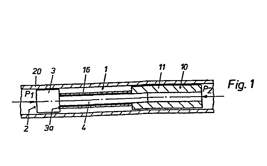
Description
Die Erfindung betrifft ein Positionierungs-Einbauteil in einem nuklearen Brennstab, dessen Hüllrohr ausserhalb einer Säule aus Tabletten- oder Partikel-Kernbrennstoff einen Brennstab-Einbau enthält, wobei der Brennstab-Einbau wenigstens ein Positionierungs-Einbauteil allein oder in Kombination mit weiteren Einbauteilen anderer Art umfasst und das Positionierungs-Einbauteil dazu dient, die Brennstoffsäule und die gegebenenfalls vorhandenen weiteren Einbauteile in dem Hüllrohr zu lokalisieren und eine axiale Ueberbelastung durch Kompensation der bei Hüllrohr, Brennstoffsäule und Brennstab-Einbau auftretenden differentiellen Längenänderungen auszuschliessen.The invention relates to a positioning installation part in a nuclear fuel rod, the cladding tube of which contains a fuel rod installation outside a column made of tablet or particle nuclear fuel, the fuel rod installation comprising at least one positioning installation part alone or in combination with other installation parts of another type and the positioning installation part serves to locate the fuel column and any further installation parts which may be present in the cladding tube and to prevent axial overloading by compensating for the differential length changes occurring in the cladding tube, fuel column and fuel rod installation.
Bei einem herkömmlichen Tabletten-Stab, d.h. einem Brennstab, der eine Säule aus Spalt- und allenfalls Brutmaterial (hier zusammenfassend mit Brennstoff bezeichnet) in Form von Tabletten und im Gasplenum Einbauten enthält, nehmen Brennstoffsäule und Einbauten im Hüllrohr definierte Positionen ein, die sie in jeder beliebigen Brennstablage beibehalten müssen.With a conventional tablet stick, i.e. a fuel rod, which contains a column of fission material and possibly brood material (here collectively referred to as fuel) in the form of tablets and internals in the gas plenum, the fuel column and internals in the cladding tube assume defined positions, which they must maintain in any fuel rod holder.
Es ist anzunehmen, dass bei der Fertigstellung, beim Transportieren und Handhaben der Brennstäbe etwa infolge von Stössen und Schlägen Beschleunigungskräfte auf die Brennstäbe einwirken, die eine Verschiebung der Brennstoffsäule und der Einbauten im Hüllrohr bewirken können. Solche Verschiebungen können nur in dem Masse zugelassen werden, als sie weder eine Schädigung noch eine dauernde Lageänderung der Brennstoffsäule und der Einbauten zur Folge haben. Bei gewöhnlichem Manipulieren mit Brennstäben lässt sich für die allenfalls auftretenden Beschleunigungskräfte ein oberer Grenzwert abschätzen, und es ist daher dafür Sorge zu tragen, dass Verschiebungen zumindest für Beschleunigungskräfte bis zu diesem fiktiven Grenzwert entweder überhaupt nicht stattfinden können oder ausreichend gedämpft und vollständig reversibel ablaufen, damit sich die Brennstoffsäule und die Einbauten in Ruhestellung des Brennstabes noch bzw. wieder in ihren definierten Positionen befinden.It can be assumed that during the completion, during transportation and handling of the fuel rods, for example as a result of shocks and impacts, acceleration forces act on the fuel rods, which cause a shift in the fuel column and Can cause installations in the cladding tube. Such shifts can only be permitted to the extent that they result in neither damage nor a permanent change in position of the fuel column and the internals. In the case of ordinary manipulation with fuel rods, an upper limit value can be estimated for the acceleration forces that may occur, and it must therefore be ensured that shifts, at least for acceleration forces up to this fictitious limit value, either cannot take place at all or are sufficiently damped and completely reversible, so that the fuel column and the internals in the rest position of the fuel rod are still or again in their defined positions.
Im Betrieb dehnen sich Hüllrohr, Brennstoffsäule und Stabeinbauten infolge der thermischen Belastung und/oder eines strahleninduzierten Schwellens der Materialien aus. Die beim Hüllrohr, bei der Brennstoffsäule und den Einbauten auftretenden Längenänderungen müssen daher mindestens so weit kompensiert werden, dass mit Sicherheit axiale Ueberbeanspruchungen derselben ausgeschlossen sind.During operation, the cladding tube, fuel column and rod internals expand due to the thermal load and / or a radiation-induced swelling of the materials. The changes in length that occur in the cladding tube, in the fuel column and in the internals must therefore be compensated for at least to such an extent that axial overstressing thereof can be ruled out with certainty.
Bei herkömmlichen Tabletten-Stäben ist im Hüllrohr eine Schraubenfeder vorgesehen, die beim Aufsetzen des Endstopfens auf das Hüllrohr leicht vorgespannt wird und die Brennstoffsäule sowie die weiteren Einbauteile des Brennstabes in axialer Richtung belastet. Mit einer solchen Feder als Positionerungs-Einbauteil werden die vorstehenden Forderungen auf durchaus befriedigende Weise erfüllt. Der aus einer Schraubenfeder bestehende Positionierungs-Einbauteil ist auch für den Zusammenbau des Brennstabes vorteilhaft, da das Hüllrohr vom in Bestrahlungsposition des Brennstabes oberen oder vom unteren Ende her gefüllt werden kann. Ein zusätzlicher Vorteil ist, dass im allgemeinen mit der Schraubenfeder allein axiale Fabrikationstoleranzen von Hüllrohr, Brennstoffsäule und Einbauteilen ausgeglichen werden können und für die erforderliche Kompensation keinerlei zusätzliche, wenn auch einfache Bauteile nötig sind.In conventional tablet rods, a helical spring is provided in the cladding tube, which is slightly pretensioned when the end plug is placed on the cladding tube and loads the fuel column and the further components of the fuel rod in the axial direction. With such a spring as a positioning installation part, the above requirements are met in a completely satisfactory manner. The positioning installation part consisting of a helical spring is also advantageous for the assembly of the fuel rod, since the cladding tube can be filled from the top or from the bottom end in the irradiation position of the fuel rod. An additional advantage is that generally only axial manufacturing tolerances of the cladding tube, fuel column and built-in parts can be compensated for with the helical spring and no additional, albeit simple, components are required for the necessary compensation.
Bei Partikel-Stäben, d.h. Brennstäben, bei denen die Brennstoffsäule aus einer Packung von in mehreren Grössenfraktionen vorliegenden Brennstoffpartikeln besteht, liegen die Verhältnisse ungünstiger. Um eine dichte und möglichst homogene Packung zu erzielen, wird der Partikelbrennstoff in eigenen Verfahren, die meistens einen Vibrierzyklus umfassen, in das Hüllrohr eingebracht. Jede nachträgliche Störung der Partikelpackung ist wegen der damit verbundenen Entmischungsvorgänge teilweise irreversibel und führt zu einer bleibenden Dichte- und Volumenänderung, so dass insbesondere auch die beim Transport und bei der Handhabung auf die Brennstäbe einwirkenden Beschleunigungskräfte (Stösse und Schläge) keine solche Störungen der Partikelpackung herbeiführen dürfen. Eine leicht vorgespannte Feder mit einer etwa dem 2- bis 10- fachen des Gewichtes des Stabinhalts entsprechenden Vorspannkraft vermag eine durch einwirkende Beschleunigungskräfte hervorgerufene Expansion der Brennstoffsäule nur ungenügend zu verhindern,und so müssen bei Verwendung solcher Federn für den Transport und für die Handhabung von Partikel-Stäben Vorkehrungen getroffen werden, durch die stärkere Stösse und Schläge mit Sicherheit ausgeschlossen werden, was in der Praxis jedoch auf erhebliche Schwierigkeiten stösst.For particle bars, i.e. The situation is more unfavorable for fuel rods in which the fuel column consists of a pack of fuel particles which are present in several size fractions. In order to achieve a tight and as homogeneous packing as possible, the particle fuel is introduced into the cladding tube in its own processes, which usually comprise a vibration cycle. Any subsequent disruption of the particle packing is partly irreversible due to the associated segregation processes and leads to a permanent change in density and volume, so that especially the acceleration forces (impacts and impacts) acting on the fuel rods during transport and handling do not cause such particle packing disruptions allowed to. A slightly pre-tensioned spring with a pre-tensioning force corresponding to about 2 to 10 times the weight of the rod content can only insufficiently prevent expansion of the fuel column caused by the acting acceleration forces, and so when using such springs they have to be used for the transport and handling of particles Precautions are taken to ensure that stronger shocks and impacts are excluded, which in practice encounters considerable difficulties.
In gewissen Fällen kann es auch aus verfahrenstechnischen Gründen erforderlich oder vorteilhaft sein, den Brennstab vom unteren Stabende her zu beladen. Bei Verwendung einer leicht vorgespannten Schraubenfeder als Positionierungs-Einbauteil ist ein solches Beladen der Partikel-Stäbe jedoch nicht möglich, da wegen der vor dem Brennstoff in das Hüllrohr eingebrachten leicht vorgespannten Feder das Vibrations-Verdichten des oberhalb der Feder befindlichen Brennstoffs nicht mehr kontrolliert durchführbar ist.In certain cases, it may also be necessary or advantageous for procedural reasons to load the fuel rod from the lower end of the rod. However, when using a slightly pre-tensioned coil spring as a positioning built-in part, such loading of the particle rods is not possible, since due to the slightly pre-tensioned spring introduced into the cladding tube, the vibration compression of the fuel located above the spring can no longer be carried out in a controlled manner .
Für Partikel-Stäbe ist deshalb eine leicht vorgespannte Schraubenfeder als Positionierungs-Einbauteil nur wenig geeignet.For particle bars, a slightly pre-tensioned coil spring is therefore not very suitable as a positioning installation part.
Ein naheliegender Ausweg wäre, als Positionierungs-Einbauteil eine stark vorgespannte Feder zu verwenden, bei der die mindestens dem 50-fachen Gewicht des Stabinhaltes entsprechende Vorspannkraft den sowohl beim Vibrationsverdichten wie auch beim Handhaben und Transportieren der Brennstäbe zu erwartenden Beschleunigungskräften gewachsen wäre. Je nach Brennstabgrösse müssten dann allerdings andere Federarten, wie z.B. Tellerfederpakete, anstelle der Schraubenfedern eingesetzt werden.An obvious way out would be to use a strongly preloaded spring as the positioning built-in part, in which the preload force corresponding to at least 50 times the weight of the rod content would be able to cope with the acceleration forces to be expected during vibration compression as well as when handling and transporting the fuel rods. Depending on the size of the fuel rod, other types of springs, such as Belleville spring assemblies can be used instead of the coil springs.
Solche stark vorspannbare Federn oder Federpakete sind jedoch verhältnismässig voluminös, so dass sie u.U. eine unzulässige Verkleinerung des für die freigesetzten Spaltgase zur Verfügung stehenden Gasplenums mit sich bringen, und zudem ist mit ihnen die im allgemeinen erwünschte flache Federcharakteristik nur beschränkt erreichbar.Such strongly preloaded springs or spring assemblies are relatively voluminous, so that they may bring about an impermissible reduction in the gas plenum available for the released cracked gases, and moreover, the generally desired flat spring characteristic can only be achieved with them to a limited extent.
Andererseits ist bei Verwendung von solchen stark vorgespannten Federn ein Füllen des Hüllrohres sowohl vom oberen wie auch vom unteren Ende her möglich.On the other hand, when using such strongly prestressed springs, it is possible to fill the cladding tube both from the upper and from the lower end.
Beim Füllen von unten müsste die Feder oder das Federpaket in vorgespanntem Zustand in das Hüllrohr eingebaut werden, was zusätzliche und der in der vorgespannten Feder gespeicherten Energie angemessene Massnahmen erforderlich macht.When filling from below, the spring or the spring assembly would have to be installed in the cladding tube in the prestressed state, which necessitates additional measures which are appropriate to the energy stored in the prestressed spring.
Beim Füllen von oben kann die Feder oder das Federpaket in bereits vorgespanntem Zustand eingebaut oder erst mit dem Einbau des Endstopfens gespannt werden. Aber auch zum Spannen mit dem Endstopfen sind verhältnismässig aufwendige Spann-und Haltevorrichtungen in der Montagebox erforderlich, und auch die zum Spannen aufzubringende Energie stellt ein zusätzliches Risiko insbesondere im Hinblick auf die Integrität eines allfällig erforderlichen a-Containments dar.When filling from above, the spring or spring assembly can be installed in the pre-tensioned state or tensioned only when the end plug is installed. However, relatively complex tensioning and holding devices are also required in the assembly box for tensioning with the end plug, and the energy to be applied for tensioning also represents an additional risk, particularly with regard to the integrity of any a containment that may be required.
Für Partikel-Stäbe ist deshalb auch eine stark vorgespannte Feder oder ein entsprechend vorgespanntes Federpaket als Positionierungs-Einbauteil wenig geeignet.For particle bars, therefore, a strongly pre-tensioned spring or a correspondingly pre-tensioned spring assembly is not very suitable as a positioning installation part.
Es war daher Aufgabe der Erfindung, ein Positionierungs-Einbauteil zu schaffen, das auch den für Partikel-Brennstäbe vorstehend genannten Anforderungen zufriedenstellend entspricht und das mit kleinem Volumen- und Materialbedarf ohne grösseren Aufwand herstellbar ist und vor allem auch einen problemlosen Einbau ohne erhöhtes Sicherheitsrisiko z.B. im Hinblick auf die Verletzlichkeit des a-Containments gewährleistet.It was therefore an object of the invention to provide a positioning built-in part which also satisfactorily meets the requirements mentioned above for particle fuel rods and which can be produced with little volume and material requirement without great effort and, above all, also a problem-free installation without increased safety risk, e.g. guaranteed with regard to the vulnerability of the a containment.
Die erfindungsgemässe Lösung der Aufgabe besteht in dem im Anspruch 1 gekennzeichneten Positionierungs-Einbauteil.The achievement of the object according to the invention consists in the positioning installation part characterized in
Ein besonderer Vorteil des erfindungsgemässen Positionierungs-Einbauteiles ist, dass für die Realisierung der Schwellenlast und der irreversiblen Verformung bei einer die Schwellenlast übersteigenden axialen Druckbelastung alle Phänomene ausgenutzt werden können, die eine nennenswerte Elastizität und entsprechend grössere Federwege ausschliessen, also:
- - Materialeigenschaften, wie inelastisches Spannungs- Dehnungsverhalten und Bruchfestigkeit bei Normal- und Schubspannungen etc.,
- - Formfaktoren und ihre Einflüsse auf Spannungen und Deformationen, wie Kanten, Kerben, Schlankheitsgrad, etc.,
- - Wechselwirkungen, wie Reibungen, Deformationsbegrenzungen, etc.,
- - zeit-, geschwindigkeits- und temperaturabhängige Effekte, wie Kriechen, Fliessen, Erweichen, Schmelzen, etc.,
welche einzeln oder in beliebigen Kombinationen in abgestimmtem Masse zur Anwendung gelangen können, wodurch über entsprechende Kraft-Weg-Verläufe, insbesondere auch ebene und abfallende, eine weitestgehende Anpassung des Deformationsverhaltens an die jeweiligen Erfordernisse ermöglicht ist.A particular advantage of the positioning built-in part according to the invention is that for the realization of the threshold load and the irreversible deformation in the event of an axial pressure load exceeding the threshold load, all phenomena can be used which exclude a noteworthy elasticity and correspondingly larger spring travel, i.e.:
- - material properties, such as inelastic stress-strain behavior and breaking strength at normal and shear stresses etc.,
- - form factors and their influences on stresses and deformations, such as edges, notches, slenderness, etc.,
- - interactions, such as friction, deformation limits, etc.,
- - time, speed and temperature-dependent effects, such as creep, flow, softening, melting, etc.,
which can be used individually or in any combination in a coordinated manner, which enables the deformation behavior to be adapted as far as possible to the respective requirements by means of corresponding force-displacement curves, in particular also flat and sloping ones.
Vorteilhaft ist ferner auch, dass keine Vorspannkräfte erforderlich sind und keine signifikante Energiespeicherung bei dem erfindungsgemässen Positionierungs-Einbauteil stattfindet.It is also advantageous that no prestressing forces are required and that there is no significant energy storage in the positioning installation part according to the invention.
Vorteilhafte Ausbildungen des Erfindungsgegenstandes sind in den abhängigen Ansprüchen angegeben.Advantageous developments of the subject matter of the invention are specified in the dependent claims.
Im folgenden wird die Erfindung anhand von bevorzugten Ausführungsbeispielen unter Bezugnahme auf die beiliegende Zeichnung näher erläutert. Auf der Zeichnung zeigen:
- Fig. 1 einen Längsschnitt durch ein Positionierungs-Einbauteil nach der Erfindung mit zwei Belastungskörpern und einem dünnwandigen Rohr als Knautschzone,
- Fig. 2 im Längsschnitt ein der Fig. 1 ähnliches Posi- tionierungs-Einbauteil mit einem perforierten Rohr als Knautschzone,
- Fig. 3 einen Längsschnitt durch ein Positionierungs-Einbauteil mit einer quergestellten Membrane, die von einem sich zur Membrane hin verjüngenden Dorn durchstossen wird,
- Fig. 4 einen Längsschnitt durch ein der Fig. 3 ähnliches Positionierungs-Einbauteil, bei dem die Membrane von einem schlanken zylindrischen Dorn durchstossen wird,
- Fig. 5 einen Längsschnitt durch ein Positionierungs-Einbauelement mit einer im wesentlichen zylindrischen Spreizfeder,
- Fig. 6 einen Querschnitt des Positionierungs-Einbauteils längs der Linie A-A in Fig.5
- Fig. 7 einen Querschnitt durch ein ähnliches Positionierungs-Einbauteil in einer etwas geänderten Ausführung und
- Fig. 8 einen Längsschnitt durch ein Positionierungs-Einbauteil mit einer Schmelzsicherung.
- 1 shows a longitudinal section through a positioning installation part according to the invention with two loading bodies and a thin-walled tube as a crumple zone,
- 2 shows in longitudinal section a positioning insert similar to FIG. 1 with a perforated tube as a crumple zone,
- 3 shows a longitudinal section through a positioning built-in part with a transverse membrane which is pierced by a mandrel tapering towards the membrane,
- 4 shows a longitudinal section through a positioning built-in part similar to FIG. 3, in which the membrane is pierced by a slim cylindrical mandrel,
- 5 shows a longitudinal section through a positioning installation element with an essentially cylindrical spreading spring,
- 6 shows a cross section of the positioning installation part along the line AA in FIG. 5
- Fig. 7 shows a cross section through a similar positioning installation part in a slightly modified version and
- 8 shows a longitudinal section through a positioning installation part with a fuse.
Jedes der auf der Zeichnung dargestellten Positionierungs-Einbauteile 1 umfasst zwei im Hüllrohr 20 eines Brennstabes leicht verschiebliche Belastungskörper 2, 10, von denen der erste Belastungskörper 2 kolbenartig mit einem zylindrischen Kopfteil 3 und einem daran angesetzten axialen Dorn 4 ausgebildet ist und der zweite Belastungskörper 10 im wesentlichen die Form einer zylindrischen Hülse hat, in der der Dorn 4 des ersten Belastungskörpers 2 geführt ist. Mit zwei solchen leicht in Massenfabrikation herstellbaren Belastungskörpern 2, 10 wird ein besonders einfacher Aufbau des Positionierungs-Einbauteiles 1 erzielt, der zudem durch' nur geringfügige Abänderungen variierbar ist, wodurch eine kostensparende Anpassung des Positionierungs-Einbauteiles an die jeweiligen Anforderungen gewährleistet ist.Each of the positioning built-in
Bei dem in Fig. 1 gezeigten Positionierungs-Einbauteil 1 ist der Dorn 4 des ersten Belastungskörpers 2 als zylindrischer Stab ausgebildet und der zweite Belastungkörper 10 besteht aus einer auf den Dorn 4 leicht aufschiebbaren Hülse 11. Auf dem Dorn 4 ist ein dünnwandiges Rohr 16 angeordnet, das im unbelasteten Ruhezustand des Positionierungs-Einbauteiles 1 die beiden Belastungskörper 2 und 10 so auf axialem Abstand hält, dass das freie Ende des Dorns 4 etwas in die Hülse 11 hineinragt. Das dünnwandige Rohr 16 kann, wie in Fig.1 gezeigt, lose auf den Dorn 4 aufgeschoben sein, wobei es an seinem einen Ende an der zwischen Dorn 4 und Kopfteil 3 vorhandenen Schulter 3a des ersten Belastungskörpers 2 anliegt und die Hülse 11 mit ihrer inneren Stirnfläche 11a am anderen Ende des dünnwandigen Rohres 16 aufliegt. Die Montage des Positionierungs-Einbauteiles erfolgt dann beim Füllen des Hüllrohres 20 durch aufeinanderfolgendes Einschieben der drei Bestandteile. Das dünnwandige Rohr 16, der erste Belastungskörper 2 und der zweite Belastungskörper 10 sind jedoch zweckmässig zu einer Baueinheit zusammengefasst, die leicht zu handhaben ist und als Ganzes in das Hüllrohr 20 eingeschoben werden kann.In the
Bei axialer Belastung, Pfeile P1, P2, verformt sich das dünnwandige Rohr 16 nach dem Ueberschreiten einer kritischen Last, der Schwellenlast, zu einem balgartigen Gebilde-, wobei SchwellenlaRt und Wellenlänge der «ich bildenden Falten im wesentlichen eine Funktion des Produktes von Radius und Wandstärke des dünnwandigen Rohres sind. Diese Koppelung beeinträchtigt die Anpassungsmöglichkeiten eines solchen mit dünnwandigem Rohr ausgestatteten Positionierungs-Einbauteiles. Die zum Falten des dünnwandigen Rohres 16 aufzubringende Deformationskraft ist aber zudem noch von den beim Falten zwischen Dorn 4 und dünnwandigem Rohr 16 wirkenden Reibungskräften abhängig, deren Stärke u.a. auch vom Spiel zwischen Dorn 4 und dünnwandigem Rohr 16 abhängt, so dass die Deformationskraft noch durch Wahl eines entsprechenden Spiels zwischen Dorn 4 und dünnwandigem Rohr 16 mehr oder weniger stark beeinflussbar ist. Von Bedeutung ist schliesslich noch die Struktur des dünnwandigen Rohres 16, wie z.B. glatt mit einheitlicher Wandstärke, profiliert mit Schwach- oder Verstärkungsstellen usw. Ein diesbezügliches Beispiel ist in Fig.2 veranschaulicht.Under axial load arrows P 1, P 2, the thin-
Das in Fig.2 dargestellte Positonierungs-Einbauteil 1 ist genauso aufgebaut wie das Positionierungs-Einbauteil der Fig.1, lediglich mit dem Unterschied, dass hier das dünnwandige Rohr 16 Perforationslöcher 17 aufweist. Bei einer solchen Ausbildung des dünnwandigen Rohres 16 wird der Deformations-Modus durch Teilung, Form und Grösse der Perforationslöcher 17 mitbestimmt und daher durch Wahl verschiedener Perforations-Lochmuster in weiten Grenzen beeinflussbar.The
Bei solchen ein dünnwandiges Rohr 16 als Knautschzone aufweisenden Positionierungs-Einbauteilen sind im wesentlichen Material, Radius, Wandstärke, Struktur, wie insbesondere vorgesehene Perforationslöcher, und Spiel des dünnwandigen Rohres 16 die Parameter, von denen sowohl die Schwellenlast wie auch der Verlauf der Kraft-Weg-Kennlinie des Positionierungs-Einbauteiles bei Belastung oberhalb der Schwellenlast abhängen. Positionierungs-Einbauteile mit einheitlichen ersten und zweiten Belastungskörpern 2 bzw. 10 können daher in einem sehr weiten Bereich allein über das dünnwandige Rohr 16 optimal an die jeweiligen Anforderungen angepasst werden. Für die gebräuchlichsten Brennstäbe zumindest wird man mit einem nur wenige unterschiedliche Typen umfassenden Satz von dünnwandigen Rohren 16 auskommen, so dass die Herstellung solcher Positionierungs-Einbauteile wirtschaftlich erfolgen kann.In the case of such positioning installation parts having a thin-
Bei den in Fig. 3 und 4 gezeigten Positionierungs-Einbauteilen 1 ist eine in den hülsenförmigen zweiten Belastungskörper 10 eingespannte Membrane 18 durch den Dorn 4 des ersten Belastungskörpers 2 belastet und wird von dem Dorn 4 durchstossen, wenn die axiale Belastung des Positionierungs-Einbauteiles die Schwellenlast überschreitet. Bei der Ausführung nach Fig. 3 ist für die Aufnahme der Membrane 18 in der Hülse 11 durch eine Erweiterungsbohrung 11a eine ringsumlaufende Innenschulter 11b gebildet, an die die Membrane 18 durch einen in die Erweiterungsbohrung 11a eingesetzten hülsenförmigen Einsatz 12 angepresst wird. Der Einsatz 12 ist dabei zweckmässig in die Erweiterungsbohrung 11a der Hülse 11 eingeschraubt. Bei dem in Fig. 3 gezeigten Ausführungsbeispiel hat der Dorn 4 einen sich konisch zur Membrane 18 hin verjüngenden, schlanken Endbereich 5, dessen abgestumpftes Ende 5a an der Membrane 18 anliegt,und der hülsenförmige Einsatz 12 hat eine solche Länge und einen solchen Innendurchmesser, dass in dieser Ruhestellung der zylindrische Schaftteil 4a des Dornes 4 etwas in den hülsenförmigen Einsatz 12 hineinragt und darin leicht verschiebbar geführt ist.-Die.Grösse der Schwellenlast ist durch die Membrane 18 und das Ende 5a des sich verjüngenden Endbereiches 5 bestimmt und kann so in einem sehr weiten Bereich variiert werden. Der Verlauf der Kraft-Weg-Kennlinie bei Belastung oberhalb der Schwellenlast ist im wesentlichen durch das Zusammenwirken des Endbereiches 5 des Dorfes 4 und der durchstossenen Membrane 18 bestimmt. Im Falle eines sich konisch verjüngenden Endbereiches 5 wird nach dem Durchstossen das Loch in der Membrane erweitert und die dabei auftretende Reibung sowie die für die Locherweiterung aufzubringende Verformungsarbeit sind für den Kennlinienverlauf massgebend. Der Verlauf der Kraft-Weg-Kennlinie ist somit sowohl durch die Form des Endbereiches 5, wie konische, konkave oder konvexe Mantelfläche, als auch durch die Ausbildung der Membrane, Material, Dicke, Schwachstellen, Löcher usw., beeinflussbar.In the
Das in Fig. 4 dargestellte Positionierungs-Einbauteil entspricht im Aufbau im wesentlichen dem Positionierungs-Einbauteil der Fig. 3, nur der Dorn 4 weist anstelle des sich konisch verjüngenden Endbereiches 5 einen abgesetzten, z.B. zylindrischen Dornabschnitt 6 auf. Wenn bei gleich ausgebildeter Membrane 18 das auf ihr aufruhende Ende 6a des Dornabschnittes 6a gleich wie das stumpfe Ende 5a des sich verjüngenden Endbereiches 5 ausgebildet ist, haben beide Positionierungs-Einbauteile (Fig. 3 und Fig.4) die gleiche Schwellenlast. Nach dem Durchstossen der Membrane 18 findet bei dem zylindrischen Dornabschnitt 6 (Fig. 4) jedoch keine weitere Locherweiterung statt und der Verlauf der Kraft-Weg-Kennlinie ist im wesentlichen durch die zwischen der Begrenzung des Membranloches und dem Dornabschnitt 6 vorhandene Reibung bestimmt.The positioning installation part shown in FIG. 4 essentially corresponds in construction to the positioning installation part of FIG. 3, only the
Für eine leichte Anpassung solcher Membrane-Positionierungs-Einbauteile kann ausser der Membrane 18 auch der Dorn 4 bzw. nur der Endbereich des Dornes 4 auswechselbar gestaltet sein und ein Satz unterschiedlicher Membranen und/ oder ein Satz unterschiedlicher Dorne 4 bzw. Dornaufsätze vorgesehen werden.In addition to the
Als eine weitere Ausführungsvariante zeigen die Figuren 5, 6 und 7 Positionierungs-Einbauteile, die wie eine Reibungsbremse funktionieren.As a further embodiment variant, FIGS. 5, 6 and 7 show positioning built-in parts which function like a friction brake.
Bei dem einen Positionierungs-Einbauteil, von dem in Fig. 5 ein Längsschnitt und in Fig. 6 ein Querschnitt längs der Linie A-A dargestellt ist, ist der zweite Belastungskörper 10 als eine zylindrische, mit einem Längsschlitz 14 versehene Spreizfeder 13 ausgebildet, die den Dorn 4 des ersten Belastungskörpers 2 satt umschliesst. Bei einer ähnlichen Ausführung, von der in Fig. 7 ein Querschnitt gezeigt ist, bildet der Dorn 4 des ersten Belastungskörpers 2 die Spreizfeder und dementsprechend hat der Dorn 4 die Form einer zylindrischen Hülse mit Längsschlitz 14, während der zweite Belastungskörper 10 als ein den Dorn 4 satt umspannendes Rohr ausgebildet ist.In the one positioning installation part, of which a longitudinal section is shown in FIG. 5 and a cross section along the line AA in FIG. 6, the
Bei diesen beiden Ausführungen ist die Schwellenlast durch die Haftreibung zwischen dem Dorn 4 und dem zweiten Belastungskörper 10 bestimmt, während der Verlauf der Kraft-Weg-Kennlinie bei Belastung oberhalb der Schwellenlast durch die Gleitreibung zwischen Dorn 4 und Belastungskörper 10 gegeben ist. Hieraus ergeben sich unmittelbar die Anpassungsmöglichkeiten, auf die daher nicht näher eingegangen werden braucht.In these two designs, the threshold load is determined by the static friction between the
Im Betrieb treten thermische sowie strahleninduzierte Längenänderungen beim Hüllrohr, bei der Brennstoffsäule und beim Stab-Einbau des Brennstabes auf, die eine axiale Belastung des Positionierungs-Einbauteiles ergeben. Die axiale Belastung des Positionierungs-Einbauteiles kann so direkt mit der Betriebstemperatur in Beziehung gesetzt und es kann verlangt werden, dass sich das Positionierungs-Einbauteil beim Erwärmen bis auf eine zwischen Raumtemperatur und Betriebstemperatur liegende Grenztemperatur als starrer Körper und bei weiterem Erwärmen als ein in axialer Richtung zusammendrückbarer Körper darbietet. Ein nach diesen Gesichtspunkten aufgebautes Positionierungs-Einbauteil ist in Fig. 8 gezeigt.During operation, thermal and radiation-induced changes in length occur in the cladding tube, in the fuel column and in the rod installation of the fuel rod, which result in an axial load on the positioning installation part. The axial loading of the positioning component can thus be directly related to the operating temperature and it can be required that the positioning component is a rigid body when heated up to a limit temperature between room temperature and operating temperature, and in the axial direction if it is heated further Towards the compressible body. A positioning fixture constructed according to these aspects is shown in FIG. 8.
Bei dem in Fig. 8 dargestellten Positionierungs-Einbauteil ist das in Ruhestellung in den hülsenförmigen zweiten Belastungskörper 10 eintauchende freie Ende des Dornes 4 durch eine bei einer kritischen Temperatur erweichende oder schmelzende Metallschicht 19 oder kurz ein Lot mit der Innenseite des zweiten Belastungskörpers 10 verbunden. Bei dem dargestellten Positionierungs-Einbauteil besteht der zweite Belastungskörper 10 aus einer am äusseren Ende durch einen Boden 15a abgeschlossenen Hülse 15 mit einer zylindrischen Innenwandung 15b, die für die Aufnahme des Dornes 4 des ersten Belastungskörpers 2 dimensioniert ist. Zur Entlüftung des durch den eingesetzten Dorn 4 abgeschlossenen Innenraumes 15c der Hülse 15 ist der erste Belastungskörper 2 mit einer durchgehenden axialen Bohrung 2a versehen. Damit bei geschmolzener Metallschicht 19 die beiden Belastungskörper 2, 10 nicht bereits unter der Wirkung von Schwerkraft ineinander geschoben werden, ist z.B. in der Hülse 15 eine Stützfeder 21 vorhanden, die einer solchen gravitationsbedingten Längenänderung des Positionierungs-Einbauteiles entgegenwirkt. Zum Einsetzen der Stützfeder 21 kann der Hülsenboden 15a z.B. einschraubbar ausgestaltet sein.In the positioning installation part shown in FIG. 8, this is in the rest position in the sleeve-shaped second part The free end of the
Im allgemeinen enthalten Brennstäbe, wie erwähnt, ausser Positionierungs-Einbauteilen noch Einbauteile anderer Art, wie etwa Reflektorelemente, Detektorelemente, Kontrollelemente usw., wobei alle Einbauteile bei jedem Brennstab in irgendeiner Reihenfolge in dem Hüllrohr untergebracht sind. Der Brennstab kann zwei oder mehrere gleiche oder unterschiedliche Positionsierungs-Einbauteile z.B. der vorstehend beschriebenen Art enthalten, die unmittelbar hintereinander oder durch je eines oder mehrere der weiteren Einbauteile anderer Art voneinander getrennt in dem Hüllrohr angeordnet sind.In general, fuel rods, as mentioned, contain, in addition to positioning installation parts, other types of installation parts, such as reflector elements, detector elements, control elements, etc., with all installation parts for each fuel rod being accommodated in the cladding tube in any order. The fuel rod can have two or more identical or different positioning components, e.g. of the type described above, which are arranged directly one behind the other or separated from one another in the cladding tube by one or more of the other built-in parts of another type.
Es ist ohne weiteres ersichtlich, dass z.B. aus den auf der Zeichnung dargestellten Positionierungs-Einbauteilen 1 vielgliedrige Verbund-Einbauteile zusammengestellt werden können, d.h. Positionierungs-Einbauteile, die aus mehreren solchen Positionierungselementen bestehen, erhalten werden können. So kann beispielsweise bei der in Fig. 1 gezeigten Ausführung der zylindrische Kopfteil 3 auf jeder Stirnseite mit einem Dorn 4 ausgestattet sein, wobei jeder Dorn mit einem eigenen zweiten Belastungskörper 10 zusammenwirkt. Die beiden, durch den gemeinsamen Kopfteil 3 miteinander in Reihe geschalteten Positionierungselemente können dabei gleicher oder verschiedener Ausführung sein. Ebenso kann als gemeinsames Verbindungsglied auch der zweite Belastungskörper 10 gewählt werden, wobei dann die mit ihm zusammenwirkenden Dorne gleicher oder verschiedener Ausführung sein können.It is readily apparent that, for example, multi-unit composite installation parts can be put together from the
Bei Hüllrohren grösseren Durchmessers können solche Positionierungselemente auch nebeneinander in einer Parellelschaltung und zudem solche Parallelschaltungen hintereinander geschaltet werden, wobei jede beliebige Kombination gewählt werden kann. Die Ausbildungs- und Kombinationsmöglichkeiten der Positionierungselemente sind dabei so zahlreich, dass mit verhältnismässig wenig Aufwand Positionierungs-Einbauteile erhalten werden können, die allen in der Praxis bei Brennstäben vorkommenden Anforderungen optimal angepasst sind.In the case of cladding tubes of larger diameter, such positioning elements can also be connected side by side in a parallel connection and, in addition, such parallel connections can be connected in series, any combination being possible. The training and combination possibilities of the positioning elements are so numerous that positioning installation parts can be obtained with relatively little effort, which are optimally adapted to all requirements that occur in fuel rod practice.
Mit den Positionierungs-Einbauteilen ist ein Ausgleich der axialen Fabrikationstoleranzen von Hüllrohr, Brennstoffsäule und Stabeinbauten auf direkte Weise nicht möglich. Für einen solchen Ausgleich sind zusätzliche Mittel erforderlich, wie etwa Abstandsstücke, insbesondere Scheiben, oder in der Längenerstreckung verstellbare Teile, z.B. ein mit einer Stellschraube ausgestatteter Endstopfen. Solche Ausgleichsmittel sind jedoch nicht aufwendig und vor allem beim Zusammenbau der Brennstäbe leicht handzuhaben.With the positioning built-in parts, it is not possible to compensate for the axial manufacturing tolerances of the cladding tube, fuel column and rod internals in a direct manner. Additional means are required for such a compensation, such as spacers, in particular disks, or parts that are adjustable in length, e.g. an end plug equipped with a set screw. Such compensation means are not complex and easy to handle, especially when assembling the fuel rods.
Claims (12)
Applications Claiming Priority (2)
| Application Number | Priority Date | Filing Date | Title |
|---|---|---|---|
| CH2511/81 | 1981-04-15 | ||
| CH251181 | 1981-04-15 |
Publications (2)
| Publication Number | Publication Date |
|---|---|
| EP0062694A2 true EP0062694A2 (en) | 1982-10-20 |
| EP0062694A3 EP0062694A3 (en) | 1982-12-08 |
Family
ID=4235430
Family Applications (1)
| Application Number | Title | Priority Date | Filing Date |
|---|---|---|---|
| EP81107174A Withdrawn EP0062694A3 (en) | 1981-04-15 | 1981-09-11 | Installation piece to be positioned in a nuclear-fuel rod |
Country Status (2)
| Country | Link |
|---|---|
| EP (1) | EP0062694A3 (en) |
| JP (1) | JPS57171287A (en) |
Cited By (2)
| Publication number | Priority date | Publication date | Assignee | Title |
|---|---|---|---|---|
| EP0935257A3 (en) * | 1998-01-13 | 1999-09-29 | Siemens Aktiengesellschaft | Nuclear reactor fuel element prepared for transport |
| US6370214B1 (en) * | 1999-07-08 | 2002-04-09 | Framtome Anp Inc. | Radiation induced growth indication apparatus for pressurized water reactor nuclear fuel assemblies |
Family Cites Families (4)
| Publication number | Priority date | Publication date | Assignee | Title |
|---|---|---|---|---|
| BE570842A (en) * | 1957-09-13 | |||
| NL238234A (en) * | 1958-04-18 | |||
| US3842238A (en) * | 1970-12-08 | 1974-10-15 | Westinghouse Electric Corp | Method of sealing nuclear fuel elements by electric welding |
| GB1507670A (en) * | 1975-12-05 | 1978-04-19 | Atomic Energy Authority Uk | Manufacture of compact nuclear fuel bodies |
-
1981
- 1981-09-11 EP EP81107174A patent/EP0062694A3/en not_active Withdrawn
- 1981-10-15 JP JP56163580A patent/JPS57171287A/en active Pending
Cited By (2)
| Publication number | Priority date | Publication date | Assignee | Title |
|---|---|---|---|---|
| EP0935257A3 (en) * | 1998-01-13 | 1999-09-29 | Siemens Aktiengesellschaft | Nuclear reactor fuel element prepared for transport |
| US6370214B1 (en) * | 1999-07-08 | 2002-04-09 | Framtome Anp Inc. | Radiation induced growth indication apparatus for pressurized water reactor nuclear fuel assemblies |
Also Published As
| Publication number | Publication date |
|---|---|
| EP0062694A3 (en) | 1982-12-08 |
| JPS57171287A (en) | 1982-10-21 |
Similar Documents
| Publication | Publication Date | Title |
|---|---|---|
| DE69500833T2 (en) | Safety device for a system on board a vehicle, in particular an aircraft | |
| EP0370427B1 (en) | Core insertions for a water-cooled nuclear reactor | |
| DE2742946C2 (en) | Spring element for holding down nuclear reactor fuel elements | |
| DE2902145A1 (en) | CARTRIDGE SLEEVE | |
| DE3615263C2 (en) | ||
| DE2713690A1 (en) | FIRE-RESISTANT DEVICE FOR WALL PUTTING PIPES MADE OF MELTABLE MATERIAL | |
| DE1764150B2 (en) | LONGITUDINAL NUCLEAR FUEL | |
| DE2637043C2 (en) | Dowel with spacer | |
| DE2320136A1 (en) | FUEL ELEMENT AND PROCEDURE FOR ITS LOADING AND RELOADING | |
| DE69106426T2 (en) | Device for the time-limited mechanical coupling and for the rapid separation of a repelling object attached to a carrier. | |
| DE1539996A1 (en) | Fuel element for a nuclear reactor | |
| DE2850968C2 (en) | Fuel assembly for a water-cooled nuclear reactor | |
| DE2261173C3 (en) | Device for detachable fixing | |
| DE69106855T2 (en) | Device for temporarily holding an object on a carrier with a one-piece holder sleeve. | |
| WO1987004674A1 (en) | Device for stepped height-adjustment of a securing or return-travel point for a safety belt or the like | |
| EP1498635A1 (en) | Adjusting element with a cylinder | |
| DE69100643T2 (en) | Device for temporally holding an object on a carrier with a predetermined breaking point calibrated for tensile forces. | |
| DE4312343A1 (en) | Overload absorber in fibre composite type of construction | |
| DE68910527T2 (en) | SHOCK ENERGY ABSORBER. | |
| EP0364910B1 (en) | Control rod for influencing the reactivity of a nuclear reactor, and arrangement of a plurality of these control rods as a control element | |
| EP0882636B1 (en) | Steering column comprising an impact-absorbing element | |
| DE60000479T2 (en) | CONTROLLED DISCONNECTING DEVICE | |
| DE69306740T2 (en) | Device for holding and ejecting an object with respect to a carrier, with a controlled sequence | |
| DE3005574A1 (en) | SELF-ACTUATING AND SELF-LOCKING VALVE | |
| DE2638645A1 (en) | RESERVE BATTERY |
Legal Events
| Date | Code | Title | Description |
|---|---|---|---|
| PUAI | Public reference made under article 153(3) epc to a published international application that has entered the european phase |
Free format text: ORIGINAL CODE: 0009012 |
|
| PUAL | Search report despatched |
Free format text: ORIGINAL CODE: 0009013 |
|
| AK | Designated contracting states |
Designated state(s): BE DE FR GB IT NL |
|
| AK | Designated contracting states |
Designated state(s): BE DE FR GB IT NL |
|
| STAA | Information on the status of an ep patent application or granted ep patent |
Free format text: STATUS: THE APPLICATION IS DEEMED TO BE WITHDRAWN |
|
| 18D | Application deemed to be withdrawn |
Effective date: 19831113 |
|
| RIN1 | Information on inventor provided before grant (corrected) |
Inventor name: BOTTA, FELIX |