EP0062710A1 - Mit einer Motorzündkerze zusammengebauter Ring - Google Patents
Mit einer Motorzündkerze zusammengebauter Ring Download PDFInfo
- Publication number
- EP0062710A1 EP0062710A1 EP81301546A EP81301546A EP0062710A1 EP 0062710 A1 EP0062710 A1 EP 0062710A1 EP 81301546 A EP81301546 A EP 81301546A EP 81301546 A EP81301546 A EP 81301546A EP 0062710 A1 EP0062710 A1 EP 0062710A1
- Authority
- EP
- European Patent Office
- Prior art keywords
- spark
- ring
- ring assembly
- attachment ring
- hollow cylinder
- Prior art date
- Legal status (The legal status is an assumption and is not a legal conclusion. Google has not performed a legal analysis and makes no representation as to the accuracy of the status listed.)
- Withdrawn
Links
- PXHVJJICTQNCMI-UHFFFAOYSA-N Nickel Chemical compound [Ni] PXHVJJICTQNCMI-UHFFFAOYSA-N 0.000 claims abstract description 14
- 238000002485 combustion reaction Methods 0.000 claims abstract description 14
- 239000010970 precious metal Substances 0.000 claims abstract description 11
- 239000010953 base metal Substances 0.000 claims abstract description 7
- 229910052759 nickel Inorganic materials 0.000 claims abstract description 6
- 239000000203 mixture Substances 0.000 claims abstract description 4
- 230000005288 electromagnetic effect Effects 0.000 claims abstract description 3
- 239000002344 surface layer Substances 0.000 claims abstract description 3
- RYGMFSIKBFXOCR-UHFFFAOYSA-N Copper Chemical compound [Cu] RYGMFSIKBFXOCR-UHFFFAOYSA-N 0.000 claims description 8
- 229910052802 copper Inorganic materials 0.000 claims description 8
- 239000010949 copper Substances 0.000 claims description 8
- 229910052751 metal Inorganic materials 0.000 claims description 8
- 239000002184 metal Substances 0.000 claims description 7
- 239000010410 layer Substances 0.000 claims description 6
- BASFCYQUMIYNBI-UHFFFAOYSA-N platinum Chemical compound [Pt] BASFCYQUMIYNBI-UHFFFAOYSA-N 0.000 claims description 6
- 229910000906 Bronze Inorganic materials 0.000 claims description 4
- 239000010974 bronze Substances 0.000 claims description 4
- KUNSUQLRTQLHQQ-UHFFFAOYSA-N copper tin Chemical compound [Cu].[Sn] KUNSUQLRTQLHQQ-UHFFFAOYSA-N 0.000 claims description 4
- BQCADISMDOOEFD-UHFFFAOYSA-N Silver Chemical compound [Ag] BQCADISMDOOEFD-UHFFFAOYSA-N 0.000 claims description 3
- PCHJSUWPFVWCPO-UHFFFAOYSA-N gold Chemical compound [Au] PCHJSUWPFVWCPO-UHFFFAOYSA-N 0.000 claims description 3
- 229910052737 gold Inorganic materials 0.000 claims description 3
- 239000010931 gold Substances 0.000 claims description 3
- 229910052697 platinum Inorganic materials 0.000 claims description 3
- 229910052709 silver Inorganic materials 0.000 claims description 3
- 239000004332 silver Substances 0.000 claims description 3
- QXZUUHYBWMWJHK-UHFFFAOYSA-N [Co].[Ni] Chemical compound [Co].[Ni] QXZUUHYBWMWJHK-UHFFFAOYSA-N 0.000 claims description 2
- 229910017052 cobalt Inorganic materials 0.000 claims description 2
- 239000010941 cobalt Substances 0.000 claims description 2
- GUTLYIVDDKVIGB-UHFFFAOYSA-N cobalt atom Chemical compound [Co] GUTLYIVDDKVIGB-UHFFFAOYSA-N 0.000 claims description 2
- 239000000446 fuel Substances 0.000 description 14
- 230000006835 compression Effects 0.000 description 5
- 238000007906 compression Methods 0.000 description 5
- 230000005672 electromagnetic field Effects 0.000 description 4
- 239000000470 constituent Substances 0.000 description 3
- VYZAMTAEIAYCRO-UHFFFAOYSA-N Chromium Chemical compound [Cr] VYZAMTAEIAYCRO-UHFFFAOYSA-N 0.000 description 2
- 230000015572 biosynthetic process Effects 0.000 description 2
- 239000011651 chromium Substances 0.000 description 2
- 239000011248 coating agent Substances 0.000 description 2
- 238000000576 coating method Methods 0.000 description 2
- 230000000694 effects Effects 0.000 description 2
- 238000003780 insertion Methods 0.000 description 2
- 230000037431 insertion Effects 0.000 description 2
- 238000005259 measurement Methods 0.000 description 2
- 230000003068 static effect Effects 0.000 description 2
- 229910000599 Cr alloy Inorganic materials 0.000 description 1
- MYMOFIZGZYHOMD-UHFFFAOYSA-N Dioxygen Chemical compound O=O MYMOFIZGZYHOMD-UHFFFAOYSA-N 0.000 description 1
- 229910000990 Ni alloy Inorganic materials 0.000 description 1
- 239000000919 ceramic Substances 0.000 description 1
- 229910052804 chromium Inorganic materials 0.000 description 1
- 229910003460 diamond Inorganic materials 0.000 description 1
- 239000010432 diamond Substances 0.000 description 1
- 229910001882 dioxygen Inorganic materials 0.000 description 1
- 239000007789 gas Substances 0.000 description 1
- 239000008246 gaseous mixture Substances 0.000 description 1
- 239000011796 hollow space material Substances 0.000 description 1
- 230000001939 inductive effect Effects 0.000 description 1
- 230000000977 initiatory effect Effects 0.000 description 1
- 230000013011 mating Effects 0.000 description 1
- 150000002739 metals Chemical class 0.000 description 1
- 238000000034 method Methods 0.000 description 1
- 229910000623 nickel–chromium alloy Inorganic materials 0.000 description 1
- 239000010935 stainless steel Substances 0.000 description 1
- 229910001220 stainless steel Inorganic materials 0.000 description 1
Images
Classifications
-
- H—ELECTRICITY
- H01—ELECTRIC ELEMENTS
- H01T—SPARK GAPS; OVERVOLTAGE ARRESTERS USING SPARK GAPS; SPARKING PLUGS; CORONA DEVICES; GENERATING IONS TO BE INTRODUCED INTO NON-ENCLOSED GASES
- H01T13/00—Sparking plugs
- H01T13/02—Details
- H01T13/08—Mounting, fixing or sealing of sparking plugs, e.g. in combustion chamber
Definitions
- This invention relates to an improved fit-on type attachment ring assembly to be detachably fitted to a conventional engine ignition plug unit.
- the invention provides a fit-on type attachment ring assembly for an engine spark plug unit and to be positioned between the latter and a cylinder cover of an internal combustion engine, characterized by a combination of a ring having an internal annular groove for reception of a dust-preventing fine wire gauze net and at least one radial air passage extending through the inner wall of said annular groove, and a hollow cylinder of a base metal and mechanically coupled with said ring, said hollow cylinder having integral outwardly extending end flanges and at least one air passage extending through the cylindrical wall thereof, said ring having a surface layer of a precious metal formed on at least the outer surfaces at its both ends contacting the inside surfaces of said end flanges of said hollow cylinder, for thereby providing a spark spreading electromagnetic effect at spark electrodes of the plug and a small supply of secondary air from outside and through thread gaps between the spark plug and the engine cylinder cover and towards the spark electrodes at the instance of fuel-air mixture.
- the precious metal layer is of platinum, gold, silver, nickel, cobalt or nickel-cobalt. However, other similar precious metal or metals may also be used.
- said base metal is copper, gun-metal or bronze.
- the net is in the form of a strip overlapped at its ends.
- the attachment ring assembly of the present invention comprises a metal ring, preferably made of copper, gun-metal, bronze or the like,, and formed with a precious metal layer applied at least on each of its end surfaces.
- the attachment ring assembly also comprises a cylinder piece made of a base metal such as copper and formed with radially, outwardly extending end flanges which are kept in tight contact with the precious metal layers on the upper and lower end surfaces of the ring thereby forming two electrostatic voltage- generating couples, copper and nickel as an example.
- This statical minor voltage generates and maintains electromagnetic fields around the plug male threads and ignition electrodes, so as to spread out the ignition sparks when the these electrodes are periodically discharged. This spark-spreading effect leads effectively the fuel consumption efficiency of the engine according to our knowledge.
- the ring assembly according to this invention is formed with at least one secondary air inducing passage leading from outside to the mating thread gaps between the plug male threads and the cylinder cover female threads which fine thread gaps form a kind of air passage.
- This high vacuum core will induce a very slight amount of secondary air from outside through the said air passages and plug thread gaps towards the spark electrodes.
- This secondary air acts as a kind of igniton catalyzer according to our belief and accelerates the combustion efficiency.
- the amount of secondary air induced into the engine cylinder at the very instance of fuel ignition is believed to be 0.01 - 0.03% of the primary combustion air according to our practical measurements.
- the compression ratio reduction may be in the order of 0.5. Theoretically, this compression ratio reduction may be believed to reduce the fuel consumption rate substantially in correspon- ing manner.
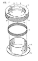
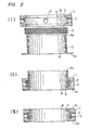
- numeral 1 represents a ring made of a base or imperfect metal such as copper, bronze,, gun metal or the like and coated with a precious metal such as platinum, gold, silver, nickel, chromium, or the like.
- a precious metal such as platinum, gold, silver, nickel, chromium, or the like.
- nickel, chromium or nickel-chromium alloy or double layer may be used for economical reasons.
- the outer surface is serrated or the like as at 1a, thereby providing a frictional touch to the operator's finger.
- annular groove 1b On the inside surface of the ring 1, there is provided an annular groove 1b, thereby providing upper and lower, inwardly projecting flanges 1c and 1d.
- a plurality of radial openings 2 are drilled through the inner wall of the annular groove 1b, and the openings 2 will serve as secondary air introducting passages from outside, as will be more fully set forth.
- Numeral 3 represents a fine-mesh,, wire gauze net strip which can be introduced into the annular groove 1b in a slightly overlapped manner at its ends. The necessary positioning can be automatically secured by the inherent resilience of the wire gauze net.3 which is made, preferably, of stainless steel.
- Numeral 4 represents a flanged cylinder to be coupled with the ring proper 1.
- This flanged cylinder 4 is also made of base metal, preferably copper. At the bottom end, this cylinder 4 is formed with an outwardly projecting bottom flange 4a.
- One or more radial openings 5 are drilled through the cylindrical portion of the cylinder 4 at a position between its ends these radial openings serving as part of an air introducing passage in service.
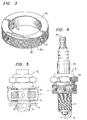
- the attachment ring 1 is detachably fitted on a conventional ignition plug 6 comprising an upper connection terminal 6a electrically connected to a centre electrode ? by a centre electrode, not shown, which is supported by a ceramic sleeve 6b.
- An opposite spark electrode 8 is arranged with its tip end adjacent to the centre electrode 7.
- the spark electrode 8 is integral with a depending male threaded metal sleeve 6c which is integral with a nut-and-ring portion 6d.
- the attachment ring 1 is directly coupled with the ignition plug 6 in an tightly contacting way at the lower end portion of the the nut-and-ring portion 6d, and without insertion of a conventional tightening washer.
- Figure 5 is an exploded schematic view of several parts of the attachment of the attachment ring, relative to the conventional plug and engine cylinder cover.
- numeral 6 represents an ignition plug as before, while numeral 9 represents a related part of an engine cylinder cover.
- the electromotive . force When the attachment ring and the cylinder cover are at 200°C under the service conditions of the engine, the electromotive . force will be 6.12 mV. This electromotive force will generate electromagnetic fields around the male screwed lower portion and the ignition electrodes of the ignition plug, as shown at B in Figure 5. The formation of electromagnetic field B contributes to spread out the ignition sparks and to serve for increasing the fuel combustion efficiency.
- a and A' shown in Figure 5 represent only schematically the formation of intermediate electromagnetic fields around the attachment ring.
Landscapes
- Chemical & Material Sciences (AREA)
- Engineering & Computer Science (AREA)
- Combustion & Propulsion (AREA)
- Spark Plugs (AREA)
Priority Applications (1)
| Application Number | Priority Date | Filing Date | Title |
|---|---|---|---|
| EP81301546A EP0062710A1 (de) | 1981-04-08 | 1981-04-08 | Mit einer Motorzündkerze zusammengebauter Ring |
Applications Claiming Priority (1)
| Application Number | Priority Date | Filing Date | Title |
|---|---|---|---|
| EP81301546A EP0062710A1 (de) | 1981-04-08 | 1981-04-08 | Mit einer Motorzündkerze zusammengebauter Ring |
Publications (1)
| Publication Number | Publication Date |
|---|---|
| EP0062710A1 true EP0062710A1 (de) | 1982-10-20 |
Family
ID=8188271
Family Applications (1)
| Application Number | Title | Priority Date | Filing Date |
|---|---|---|---|
| EP81301546A Withdrawn EP0062710A1 (de) | 1981-04-08 | 1981-04-08 | Mit einer Motorzündkerze zusammengebauter Ring |
Country Status (1)
| Country | Link |
|---|---|
| EP (1) | EP0062710A1 (de) |
Citations (3)
| Publication number | Priority date | Publication date | Assignee | Title |
|---|---|---|---|---|
| GB2017816A (en) * | 1978-03-13 | 1979-10-10 | Ito K | Ignition plug accessories |
| US4214567A (en) * | 1978-10-11 | 1980-07-29 | Kunihiko Miyaji | Internal combustion engines |
| US4232242A (en) * | 1978-08-07 | 1980-11-04 | Hsu Yun T | Sparking plug with efficient air supplying system and a removable sitting device |
-
1981
- 1981-04-08 EP EP81301546A patent/EP0062710A1/de not_active Withdrawn
Patent Citations (3)
| Publication number | Priority date | Publication date | Assignee | Title |
|---|---|---|---|---|
| GB2017816A (en) * | 1978-03-13 | 1979-10-10 | Ito K | Ignition plug accessories |
| US4232242A (en) * | 1978-08-07 | 1980-11-04 | Hsu Yun T | Sparking plug with efficient air supplying system and a removable sitting device |
| US4214567A (en) * | 1978-10-11 | 1980-07-29 | Kunihiko Miyaji | Internal combustion engines |
Similar Documents
| Publication | Publication Date | Title |
|---|---|---|
| US4219001A (en) | Method and apparatus for accumulating fuel particles in a portion of a combustion chamber | |
| US8216015B2 (en) | High thread ground shield | |
| US8049399B2 (en) | High power discharge fuel ignitor | |
| CN101496241B (zh) | 小直径的长距离火花塞 | |
| DE59800197D1 (de) | Zündkerze für eine Brennkraftmaschine | |
| JPS61265404A (ja) | バ−ナ | |
| US4465952A (en) | Spark plug for internal combustion engines | |
| US5464345A (en) | Gaseous fuel burner and method of making same | |
| US7816845B2 (en) | Ceramic electrode and ignition device therewith | |
| US2957099A (en) | Spark plugs | |
| JPH0258756B2 (de) | ||
| EP0062710A1 (de) | Mit einer Motorzündkerze zusammengebauter Ring | |
| ES8707826A1 (es) | Perfeccionamientos en una bujia de encendido para motores de combustion interna | |
| US4284054A (en) | Lean air-fuel mixture attraction method and attraction electrode plug in engine | |
| AU8389398A (en) | Spark plug | |
| US5911572A (en) | Spark ignition electrode assembly for gas stove top burner | |
| ES8400536A1 (es) | "un motor de pistones de combustion interna". | |
| US3940649A (en) | Spark plug construction | |
| ES8703967A1 (es) | Un dispositivo electrico de puesta en marcha para un motor de combustion interna | |
| GB2030643A (en) | Electrostatic Fields in Engine Cylinder Combustion Chambers | |
| US2874322A (en) | Low tension spark plug | |
| DE3866956D1 (de) | Kraftstoff-einspritzduese fuer brennkraftmaschinen. | |
| JP3671485B2 (ja) | 内燃機関用スパークプラグ | |
| EP0222336A3 (de) | Piezoelektrische Gaszündvorrichtung | |
| JPS6132786B2 (de) |
Legal Events
| Date | Code | Title | Description |
|---|---|---|---|
| PUAI | Public reference made under article 153(3) epc to a published international application that has entered the european phase |
Free format text: ORIGINAL CODE: 0009012 |
|
| AK | Designated contracting states |
Designated state(s): BE CH DE FR GB IT |
|
| STAA | Information on the status of an ep patent application or granted ep patent |
Free format text: STATUS: THE APPLICATION IS DEEMED TO BE WITHDRAWN |
|
| 18D | Application deemed to be withdrawn |
Effective date: 19830926 |
|
| RIN1 | Information on inventor provided before grant (corrected) |
Inventor name: GOTO, ENAMI |