EP0062713A1 - Méthode pour fabriquer une lampe fluorescente et lampe fluorescente obtenue par cette méthode - Google Patents
Méthode pour fabriquer une lampe fluorescente et lampe fluorescente obtenue par cette méthode Download PDFInfo
- Publication number
- EP0062713A1 EP0062713A1 EP81301574A EP81301574A EP0062713A1 EP 0062713 A1 EP0062713 A1 EP 0062713A1 EP 81301574 A EP81301574 A EP 81301574A EP 81301574 A EP81301574 A EP 81301574A EP 0062713 A1 EP0062713 A1 EP 0062713A1
- Authority
- EP
- European Patent Office
- Prior art keywords
- envelope
- fluorescent lamp
- pair
- winding
- leg parts
- Prior art date
- Legal status (The legal status is an assumption and is not a legal conclusion. Google has not performed a legal analysis and makes no representation as to the accuracy of the status listed.)
- Granted
Links
- 238000004519 manufacturing process Methods 0.000 title claims abstract description 10
- 238000000034 method Methods 0.000 title claims description 8
- 238000004804 winding Methods 0.000 claims abstract description 27
- 238000005452 bending Methods 0.000 claims abstract description 13
- QSHDDOUJBYECFT-UHFFFAOYSA-N mercury Chemical compound [Hg] QSHDDOUJBYECFT-UHFFFAOYSA-N 0.000 claims abstract description 10
- 229910052753 mercury Inorganic materials 0.000 claims abstract description 10
- 239000011521 glass Substances 0.000 claims abstract description 8
- OAICVXFJPJFONN-UHFFFAOYSA-N Phosphorus Chemical compound [P] OAICVXFJPJFONN-UHFFFAOYSA-N 0.000 claims description 17
- 239000000463 material Substances 0.000 claims description 17
- 239000000725 suspension Substances 0.000 claims description 8
- 239000011248 coating agent Substances 0.000 claims description 7
- 238000000576 coating method Methods 0.000 claims description 7
- 229910000497 Amalgam Inorganic materials 0.000 claims description 3
- 229910052738 indium Inorganic materials 0.000 claims description 2
- APFVFJFRJDLVQX-UHFFFAOYSA-N indium atom Chemical compound [In] APFVFJFRJDLVQX-UHFFFAOYSA-N 0.000 claims description 2
- 238000007789 sealing Methods 0.000 claims description 2
- 238000005192 partition Methods 0.000 description 7
- 230000000712 assembly Effects 0.000 description 2
- 238000000429 assembly Methods 0.000 description 2
- 239000005361 soda-lime glass Substances 0.000 description 2
- 241001621399 Lampris Species 0.000 description 1
- 238000009833 condensation Methods 0.000 description 1
- 230000005494 condensation Effects 0.000 description 1
- 238000001035 drying Methods 0.000 description 1
- 238000005286 illumination Methods 0.000 description 1
- 230000000717 retained effect Effects 0.000 description 1
Images

Classifications
-
- H—ELECTRICITY
- H01—ELECTRIC ELEMENTS
- H01J—ELECTRIC DISCHARGE TUBES OR DISCHARGE LAMPS
- H01J61/00—Gas-discharge or vapour-discharge lamps
- H01J61/02—Details
- H01J61/30—Vessels; Containers
Definitions
- the present invention relates to a fluorescent lamp and a method of manufacturing a fluorescent lamp.
- Fluorescent lamps have been used as a general source of illumination for many years.
- a fluorescent lamp has high lighting efficiency and a low consumption of electric power in comparison with an incandescent lamp and a fluorescent lamp employing a lamp base of an incandescent lamp, e.g. a screw base, has been developed.
- a fluorescent lamp employing a lamp base of an incandescent lamp, e.g. a screw base, has been developed.
- a fluorescent lamp in order to interchange such a fluorescent lamp with a compact incandescent lamp, it is necessary for the fluorescent lamp to have a folded envelope because, in order to obtain about the same brightness as with an incandescent lamp, it is necessary for the fluorescent lamp's envelope to have a certain length.
- Such a fluorescent lamp is known, for example, from U.S. Patents Nos. 3,551,736 and 4,199,708.
- Such a folded or winding envelope is usually surrounded with a bowl or a cover. Consequently, the temperature of the fluorescent lamp rises on
- a fluorescent lamp comprising:
- a fluorescent lamp which comprises a winding envelope, the method including the steps of:
- a bowl-shaped base member 1 having a plurality of ventilating holes 1' provides a conventional incandescent lamp base 2 at one end thereof and at the other end of the base member 1 there is formed a globe 3.
- a partition plate 4 divides the base member from the globe and defines two spaces, i.e. a base member space and a globe space.
- Reference numeral 5 refers designates a fluorescent lamp, the latter having a compact, winding envelope 6 formed as follows.
- the envelope 6 is made by bending a straight glass tube into a U-shape to form a first bent part 6a and a pair of first leg parts 6b, followed by the bending of each leg part of the pair of leg parts 6b into a second U-shape to form a pair of second bent parts 6c and two pairs of second leg parts 6d.
- the thus formed envelope 6 is of a small and compact shape and may be referred to as a saddle-shaped envelope.
- the winding envelope 6 has a layer of phosphor material on the inner surface thereof.
- a respective electrode 7 is mounted at each end of the envelope 6 and predetermined amounts of mercury and rare gas are sealed in the envelope 6.
- the envelope 6 is formed with a projection, i.e. a sealed-off tip part 8, at the first bent part 6a.
- the fluorescent lamp 5 is fixed to the partition plate 4 with first bent part 6a facing the partition plate 4, the tip part 8 projecting into the base member spade through a hole 4' formed in the partition plate 4.
- a ballast 9 is also fixed to the partition plate 4 adjacent the fluorescent lamp 5.
- the tip part 8 is shielded by the partition plate 4 so that heat radiated from the fluorescent lamp and the ballast 9 is shielded by the partition plate 4. Moreover, the part 8 is exposed to open air via the ventilating holes 1' of the base member 1. Consequently, the part 8 becomes the lowest temperature part of the fluorescent lamp 5.
- the fluorescent lamp 5 It is thus possible for the fluorescent lamp 5 to maintain high lighting efficiency in spite of relatively high surrounding temperatures such as in the bowl 3. This is due to the fact that the mercury vapour pressure in the fluorescent lamp 5 is now determined by the coolest wall part of the fluorescent lamp.
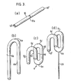
- a centre part 10a of a conventional straight glass tube 10 having openings 10' is heated to a working temperature by a heater (not shown).
- the glass tube made of soda-lime glass, has a diameter of approximately 17.5mm and has a softening point of about 700°C.
- the straight tube 10 softened by the heater is bent into a U-shape having the first bent part 6a and the pair of first leg parts 6b as shown in Figure 3b.
- each of the pair of leg parts 6b is heated to a working temperature and each is bent into a second U-shape in a direction perpendicular to the plane of the first U-shape to form the pair of second bent parts 6c and the two pairs of second leg parts 6d as shown in Figure 3c.
- an exhaust tube 20 made of soda-lime glass is fixed to the first bent part 6a in a manner so as to point in the same direction as the openings 10',as shown in Figure 3d.
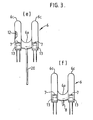
- the winding envelope 6 provided with the exhaust tube 20, is then positioned with the openings 10' thereof facing upward. Then, a suspension of phosphor material is poured into the openings 10'. Following this, the envelope 6 is turned upside down so that the openings 10' face downward. Thus, excess suspension from the coating step is drained through the exhaust tube 20 and the openings 10'. Therefore, after drying the suspension of phosphor material, a uniform layer of phosphor material 12 is formed on the inner surface of the winding envelope 6.
- the exhaust tube 20 is fused together near the bent part 6a to form the tip part 8 and seal the envelope, the remainder of the tube 20 being removed. Thereby, the tip part 8 is formed at the first bent part 6a.
- the exhaust tube 20 it is possible to form a uniform thickness of the layer 12 of phosphor material, by employing the exhaust tube 20 at the first bent part 6a. That is, since the position of the exhaust tube 20 is at a point of symmetry of the winding envelope 6, on draining the excess phosphor material suspension, it drains evenly from the openings 10' and the exhaust tube 20 and is prevented from collecting at the bent parts 6a and 6b.
Landscapes
- Vessels And Coating Films For Discharge Lamps (AREA)
Priority Applications (2)
| Application Number | Priority Date | Filing Date | Title |
|---|---|---|---|
| DE8181301574T DE3172957D1 (en) | 1981-04-10 | 1981-04-10 | A method of manufacturing a fluorescent lamp and a fluorescent lamp obtained by this method |
| EP81301574A EP0062713B1 (fr) | 1981-04-10 | 1981-04-10 | Méthode pour fabriquer une lampe fluorescente et lampe fluorescente obtenue par cette méthode |
Applications Claiming Priority (1)
| Application Number | Priority Date | Filing Date | Title |
|---|---|---|---|
| EP81301574A EP0062713B1 (fr) | 1981-04-10 | 1981-04-10 | Méthode pour fabriquer une lampe fluorescente et lampe fluorescente obtenue par cette méthode |
Publications (2)
| Publication Number | Publication Date |
|---|---|
| EP0062713A1 true EP0062713A1 (fr) | 1982-10-20 |
| EP0062713B1 EP0062713B1 (fr) | 1985-11-21 |
Family
ID=8188274
Family Applications (1)
| Application Number | Title | Priority Date | Filing Date |
|---|---|---|---|
| EP81301574A Expired EP0062713B1 (fr) | 1981-04-10 | 1981-04-10 | Méthode pour fabriquer une lampe fluorescente et lampe fluorescente obtenue par cette méthode |
Country Status (2)
| Country | Link |
|---|---|
| EP (1) | EP0062713B1 (fr) |
| DE (1) | DE3172957D1 (fr) |
Cited By (3)
| Publication number | Priority date | Publication date | Assignee | Title |
|---|---|---|---|---|
| US4794301A (en) * | 1986-08-19 | 1988-12-27 | Kabushiki Kaisha Toshiba | Fluorescent lamp having a convoluted discharge passage and fluorescent lamp apparatus incorporating the same |
| GB2278718A (en) * | 1993-06-01 | 1994-12-07 | Eldon Kai Choi Lee | Method of manufacture of a discharge tube |
| WO2009115373A1 (fr) * | 2008-03-20 | 2009-09-24 | Osram Gesellschaft mit beschränkter Haftung | Enceinte à décharge pour une lampe à décharge et lampe à décharge |
Citations (8)
| Publication number | Priority date | Publication date | Assignee | Title |
|---|---|---|---|---|
| GB668259A (en) * | 1949-11-03 | 1952-03-12 | British Thomson Houston Co Ltd | Improvements in and relating to methods of shaping vitreous tubes |
| US3152278A (en) * | 1959-06-12 | 1964-10-06 | Patent Treuhand Ges Fuer Elektrische Gluehlampen Mbh | Fluorescent lamp with low melting amalgam filling |
| GB1068704A (en) * | 1964-07-22 | 1967-05-10 | Philips Electronic Associated | Improvements in and relating to methods of introducing sodium into a discharge vessel |
| US3551736A (en) * | 1968-04-02 | 1970-12-29 | Gunther Anthony Doehner | Fluorescent lamps constructed for use in conventional light fixtures |
| GB1503636A (en) * | 1975-06-20 | 1978-03-15 | Philips Ltd | Lowpressure mercury vapour discharge lamp |
| EP0000966A1 (fr) * | 1977-08-23 | 1979-03-07 | Koninklijke Philips Electronics N.V. | Lampe à décharge basse pression à vapeur de mercure |
| US4199708A (en) * | 1977-08-23 | 1980-04-22 | U.S. Philips Corporation | Low-pressure mercury vapor discharge lamp |
| GB2033653A (en) * | 1978-10-26 | 1980-05-21 | Philips Nv | Low-pressure mercury vapour discharge lamp |
Family Cites Families (1)
| Publication number | Priority date | Publication date | Assignee | Title |
|---|---|---|---|---|
| AU529323B2 (en) * | 1979-09-29 | 1983-06-02 | K.K. Toshiba | Fluorescent lamp |
-
1981
- 1981-04-10 DE DE8181301574T patent/DE3172957D1/de not_active Expired
- 1981-04-10 EP EP81301574A patent/EP0062713B1/fr not_active Expired
Patent Citations (8)
| Publication number | Priority date | Publication date | Assignee | Title |
|---|---|---|---|---|
| GB668259A (en) * | 1949-11-03 | 1952-03-12 | British Thomson Houston Co Ltd | Improvements in and relating to methods of shaping vitreous tubes |
| US3152278A (en) * | 1959-06-12 | 1964-10-06 | Patent Treuhand Ges Fuer Elektrische Gluehlampen Mbh | Fluorescent lamp with low melting amalgam filling |
| GB1068704A (en) * | 1964-07-22 | 1967-05-10 | Philips Electronic Associated | Improvements in and relating to methods of introducing sodium into a discharge vessel |
| US3551736A (en) * | 1968-04-02 | 1970-12-29 | Gunther Anthony Doehner | Fluorescent lamps constructed for use in conventional light fixtures |
| GB1503636A (en) * | 1975-06-20 | 1978-03-15 | Philips Ltd | Lowpressure mercury vapour discharge lamp |
| EP0000966A1 (fr) * | 1977-08-23 | 1979-03-07 | Koninklijke Philips Electronics N.V. | Lampe à décharge basse pression à vapeur de mercure |
| US4199708A (en) * | 1977-08-23 | 1980-04-22 | U.S. Philips Corporation | Low-pressure mercury vapor discharge lamp |
| GB2033653A (en) * | 1978-10-26 | 1980-05-21 | Philips Nv | Low-pressure mercury vapour discharge lamp |
Cited By (3)
| Publication number | Priority date | Publication date | Assignee | Title |
|---|---|---|---|---|
| US4794301A (en) * | 1986-08-19 | 1988-12-27 | Kabushiki Kaisha Toshiba | Fluorescent lamp having a convoluted discharge passage and fluorescent lamp apparatus incorporating the same |
| GB2278718A (en) * | 1993-06-01 | 1994-12-07 | Eldon Kai Choi Lee | Method of manufacture of a discharge tube |
| WO2009115373A1 (fr) * | 2008-03-20 | 2009-09-24 | Osram Gesellschaft mit beschränkter Haftung | Enceinte à décharge pour une lampe à décharge et lampe à décharge |
Also Published As
| Publication number | Publication date |
|---|---|
| EP0062713B1 (fr) | 1985-11-21 |
| DE3172957D1 (en) | 1986-01-02 |
Similar Documents
| Publication | Publication Date | Title |
|---|---|---|
| CA1146210A (fr) | Lampe fluorescente, methode de fabrication et appareil d'eclairage correspondant | |
| US4281267A (en) | High intensity discharge lamp with coating on arc discharge tube | |
| EP0769803A2 (fr) | Lampe fluorescente sans électrodes | |
| JPH0434259B2 (fr) | ||
| JPS6021461B2 (ja) | 放電ランプの製造方法 | |
| US4441050A (en) | Single-ended low pressure discharge lamp and method of manufacture | |
| US4527089A (en) | Compact fluorescent lamp | |
| EP0062713B1 (fr) | Méthode pour fabriquer une lampe fluorescente et lampe fluorescente obtenue par cette méthode | |
| US3504215A (en) | Planar fluorescent lamp with integral amalgam type mercury-vapor pressure control component | |
| GB2123601A (en) | Discharge lamps | |
| US5296780A (en) | Arc discharge lamp having cementless right-angle base members | |
| JPS59230251A (ja) | コンパクトけい光ランプ用の金属のア−ク指向器 | |
| EP0181398B1 (fr) | Lampe a decharge a basse pression | |
| JPH0361307B2 (fr) | ||
| JP3436283B2 (ja) | 蛍光ランプの製造方法 | |
| JP3617228B2 (ja) | 蛍光ランプの製造方法 | |
| JPH0969309A (ja) | 蛍光ランプ装置 | |
| JPS6335484Y2 (fr) | ||
| JPS6330107Y2 (fr) | ||
| CA1213933A (fr) | Generateur d'arc pour lampe fluorescente compacte | |
| JPH0346457Y2 (fr) | ||
| KR840002454B1 (ko) | 곡관형 형광램프의 제조방법 | |
| JPS58152363A (ja) | 低圧水銀蒸気放電灯 | |
| JPS6349343B2 (fr) | ||
| JPS6347102B2 (fr) |
Legal Events
| Date | Code | Title | Description |
|---|---|---|---|
| PUAI | Public reference made under article 153(3) epc to a published international application that has entered the european phase |
Free format text: ORIGINAL CODE: 0009012 |
|
| 17P | Request for examination filed |
Effective date: 19820421 |
|
| AK | Designated contracting states |
Designated state(s): DE FR GB IT NL |
|
| RBV | Designated contracting states (corrected) |
Designated state(s): DE FR GB IT NL |
|
| RAP1 | Party data changed (applicant data changed or rights of an application transferred) |
Owner name: KABUSHIKI KAISHA TOSHIBA |
|
| ITF | It: translation for a ep patent filed | ||
| GRAA | (expected) grant |
Free format text: ORIGINAL CODE: 0009210 |
|
| AK | Designated contracting states |
Designated state(s): DE FR GB IT NL |
|
| REF | Corresponds to: |
Ref document number: 3172957 Country of ref document: DE Date of ref document: 19860102 |
|
| ET | Fr: translation filed | ||
| PLBE | No opposition filed within time limit |
Free format text: ORIGINAL CODE: 0009261 |
|
| STAA | Information on the status of an ep patent application or granted ep patent |
Free format text: STATUS: NO OPPOSITION FILED WITHIN TIME LIMIT |
|
| 26N | No opposition filed | ||
| PGFP | Annual fee paid to national office [announced via postgrant information from national office to epo] |
Ref country code: FR Payment date: 19910322 Year of fee payment: 11 |
|
| PGFP | Annual fee paid to national office [announced via postgrant information from national office to epo] |
Ref country code: GB Payment date: 19910326 Year of fee payment: 11 |
|
| PGFP | Annual fee paid to national office [announced via postgrant information from national office to epo] |
Ref country code: DE Payment date: 19910410 Year of fee payment: 11 |
|
| ITTA | It: last paid annual fee | ||
| PGFP | Annual fee paid to national office [announced via postgrant information from national office to epo] |
Ref country code: NL Payment date: 19910430 Year of fee payment: 11 |
|
| PG25 | Lapsed in a contracting state [announced via postgrant information from national office to epo] |
Ref country code: GB Effective date: 19920410 |
|
| PG25 | Lapsed in a contracting state [announced via postgrant information from national office to epo] |
Ref country code: NL Effective date: 19921101 |
|
| GBPC | Gb: european patent ceased through non-payment of renewal fee | ||
| NLV4 | Nl: lapsed or anulled due to non-payment of the annual fee | ||
| PG25 | Lapsed in a contracting state [announced via postgrant information from national office to epo] |
Ref country code: FR Effective date: 19921230 |
|
| PG25 | Lapsed in a contracting state [announced via postgrant information from national office to epo] |
Ref country code: DE Effective date: 19930101 |
|
| REG | Reference to a national code |
Ref country code: FR Ref legal event code: ST |