EP0062767B1 - Four électrique à arc - Google Patents
Four électrique à arc Download PDFInfo
- Publication number
- EP0062767B1 EP0062767B1 EP82101898A EP82101898A EP0062767B1 EP 0062767 B1 EP0062767 B1 EP 0062767B1 EP 82101898 A EP82101898 A EP 82101898A EP 82101898 A EP82101898 A EP 82101898A EP 0062767 B1 EP0062767 B1 EP 0062767B1
- Authority
- EP
- European Patent Office
- Prior art keywords
- support arm
- electrode
- electric
- arc furnace
- vibration
- Prior art date
- Legal status (The legal status is an assumption and is not a legal conclusion. Google has not performed a legal analysis and makes no representation as to the accuracy of the status listed.)
- Expired
Links
Images


Classifications
-
- H—ELECTRICITY
- H05—ELECTRIC TECHNIQUES NOT OTHERWISE PROVIDED FOR
- H05B—ELECTRIC HEATING; ELECTRIC LIGHT SOURCES NOT OTHERWISE PROVIDED FOR; CIRCUIT ARRANGEMENTS FOR ELECTRIC LIGHT SOURCES, IN GENERAL
- H05B7/00—Heating by electric discharge
- H05B7/02—Details
- H05B7/10—Mountings, supports, terminals or arrangements for feeding or guiding electrodes
Definitions
- the invention relates to an electric arc furnace, in particular for melting steel, with one or more electrodes, each held by a support arm, in which a vibration damper for pitching vibrations is arranged at least on the support arm of the most vulnerable electrode in the support arm / electrode plane , which compensates for the pitching vibrations by vibrations in opposite phases.
- Such electric arc furnaces are usually equipped with three electrodes and operated as a three-phase furnace.
- they are equipped with an electrode and operated as a single-phase furnace.
- a problem which has been known for a long time in such furnaces is that the electrodes break at the clamping point on the support arm.
- the breakage rate was 5 to 10 breaks per month. After switching to higher melting rates (higher current), the breakage rate increased to 30 to 40 a month.
- the middle electrode was particularly at risk, i.e. if the electrodes were arranged in a triangle and if the electrodes were held on parallel support arms, the electrode on the middle, shorter support arm.
- vibration dampers on the electrode arms. These vibration dampers are arranged in such a way that they dampen vibrations occurring perpendicular to the common plane of the electrode and electrode arm.
- the vibration dampers consist of an inert mass which is held in a middle position by springs and the movement of which is damped by damping means.
- the inertial mass is arranged in a housing filled with hydraulic fluid, while in another embodiment it is connected to a friction brake.
- the damping effect is based on the fact that the vibration energy emanating from the support arm / electrode system and transferred to the inertial mass is converted into frictional heat. Such a reduction in the vibrations of the support arm / electrode system is not particularly effective (DE-OS 2 837 741, Fig. 1 and Fig. 2).
- a vibration damper of the type mentioned at the outset is also known for reducing the breakage rate of electrode breaks.
- This vibration damper is designed as an active vibration damper in that the pitching vibrations of the electrode are detected by a sensor and evaluated in a regulating and control device that controls a vibrator that mechanically engages the electrode in such a way that its vibrations are in phase opposition to the vibrations of the electrode (DE -OS 2 837 741, Fig. 12).
- the invention has for its object to provide an electric arc furnace in which the risk of breakage of the electrodes is reduced in a simple manner compared to the conventional arc furnaces.
- the vibration damper is designed as a vibration system consisting of inert mass and spring, the natural frequency of which is matched to the pitch natural frequency of the vibration system of the support arm / electrode.
- the vibration damper according to the invention is a passive vibration damper. If its vibration level corresponds to the vibration level of the pitching vibrations of the support arm / electrode system and its natural frequency matches the natural frequency of the support arm / electrode system, the vibration damper is excited to oscillations in phase by the vibrations of the support arm / electrode system.
- the forces of the inertial mass of the vibration damper built up in the vibration absorber with this excitation counteract the excitation forces of the support arm / electrode system and therefore suppress the excitation forces as they arise so that an oscillation with a large amplitude cannot build up. For this reason, the use of the vibration damper makes it unnecessary to stiffen the support arm construction in particular and / or to manufacture the electrodes from a mechanically more resistant material.
- the low load due to the vibrations also leads to a reduced load on the drive and the guidance of the support arm construction.
- the fracture rate can already be reduced considerably if a vibration damper is only arranged on the middle support arm.
- the electrode of the middle support arm is particularly at risk because the vibrations of the electrode lie in the plane of the electrode and the support arm, i.e. in a plane in which the construction is relatively stiff, while the vibrations of the outer electrodes, whose plane of vibration does not match that Level of the electrodes and the support arms coincides, can be partially absorbed by torsion of the support arms.
- the spring of the vibration damper is parallel to a damper that widens the resonance.
- the damper only has the purpose of flattening the resonance point of the vibration damper so that the Ab adjustment of the vibration damper to the support arm / electrode system requires no great care.
- a particularly compact vibration damper is characterized in that the inertial mass has a pin which is guided in a stationary sleeve, on the outside of which the spring designed as a helical spring is guided.
- the inert mass can be cup-shaped and enclose the spring.
- the inertial mass of the vibration absorber preferably carries a vibration pickup which, when a predeterminable amplitude value of the vibrations of the inertial mass is exceeded, gives a switch-off signal to the power supply to the electrode or electrodes. Switching off the power supply also counteracts the build-up of vibrations.
- the inertial mass of the vibration damper can additionally form the armature of an electromagnet, the coil of which is controlled in dependence on the control signal of a vibration sensor for the pitching vibrations of the vibration system support arm / electrode in the support arm / electrode level such that the as a result, vibration absorbers on the support arm excited to vibrations in the plane of the support arm / electrode build up forces which counteract the excitation forces of the arc which are effective at the lower end of the electrode.
- the vibration sensor can be arranged on the inertial mass.
- the arc furnace 1 shown in FIGS. 1 and 2 is closed by a cover 2 in which three openings 3, 4, 5 are provided for electrodes 6, 7, 8 arranged vertically downwards, parallel to one another and at the corner points of an equilateral triangle .
- a support arm 9, 10, 11 is assigned to each electrode 6 to 8.
- the support arms 9 to 11 run parallel to each other.
- the two outer support arms 10, 11 are of equal length and longer than the middle support arm 9. All of the support arms 9 to 11 are each held on a stand 12 which is adjustable in height. This height adjustability makes it possible to change the distance of the electrode ends from the bath level 13.
- a vibration damper 14, 15, 16 is coupled to the free ends of the support arms 9 to 11.
- the vibration damper has a rotationally symmetrical structure.
- the vibration absorber shown in Fig. 3 consists of a circular cylindrical pot 17, a central pin 18, a pin 18 and pot 17 crosshead 19 connecting parts 17 to 19 form the so-called "inert" mass of the vibration absorber, a fixed guide sleeve 20 for the pin 18, a helical spring 21 arranged on the outside on the guide sleeve 20 in the annular gap between the pin 18 and the pot 17, and the end face of the pot 17 and the pin 18 on a support 22 coupling damping body 23, 24.
- the entire unit is encapsulated in a housing 25.
- the parts forming the inertial mass of the vibration absorber (hollow cylindrical pot 17, pin 18, crosshead 19) and the spring 21 are tuned in their natural frequency to the natural frequency of the oscillating system consisting of support arm 9 to 11 and electrode 6 to 8.
- a vibration sensor 26, 27 can be provided on the inertial mass 17 to 19 of the vibration absorber 14 to 16 or the support arms 9 to 11, which controls the current to be supplied to the electrodes 6 to 8 via a control device in such a way that when a predeterminable maximum value is exceeded, the Power supply for one or more phases is interrupted. This current interruption dampens the system.
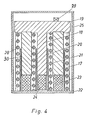
- an active vibration absorber or, instead of the purely passive vibration absorber described above, a combination of passive and active vibration absorbers according to FIG. 4 can be provided.
- the basic structure of such a vibration damper corresponds to that of the passive vibration damper, as a comparison of FIGS. 3 and 4 shows.
- the active vibration damper has an electromagnet, the armature of which is formed by at least part of the inertial mass, in the exemplary embodiment the hollow cylindrical part 17.
- This hollow cylindrical part 17 is surrounded by an electrical coil 28 which is arranged on a stationary guide sleeve 30.
- the power supply to the coil 28 is controlled by a control device, not shown.
- the control device receives a control signal from a vibration sensor 29 which is arranged on the inertial mass 17 to 19.
- the control is thus carried out as a function of the vibrations picked up by the vibration sensor 29 in such a way that the vibration damper is excited to vibrate in such a way that the spring 21 and the damping bodies 23, 24 Forces on the support arm 9 to 11 are built up, which counteract the excitation forces at the lower end of the electrodes 6 to 8 by the arc.
Landscapes
- Physics & Mathematics (AREA)
- Engineering & Computer Science (AREA)
- Plasma & Fusion (AREA)
- Furnace Details (AREA)
- Vertical, Hearth, Or Arc Furnaces (AREA)
- Discharge Heating (AREA)
Claims (10)
Priority Applications (1)
| Application Number | Priority Date | Filing Date | Title |
|---|---|---|---|
| AT82101898T ATE15428T1 (de) | 1981-04-08 | 1982-03-10 | Elektrischer lichtbogenofen. |
Applications Claiming Priority (2)
| Application Number | Priority Date | Filing Date | Title |
|---|---|---|---|
| DE3114145A DE3114145C2 (de) | 1981-04-08 | 1981-04-08 | Elektrischer Lichtbogenofen |
| DE3114145 | 1981-04-08 |
Publications (2)
| Publication Number | Publication Date |
|---|---|
| EP0062767A1 EP0062767A1 (fr) | 1982-10-20 |
| EP0062767B1 true EP0062767B1 (fr) | 1985-09-04 |
Family
ID=6129657
Family Applications (1)
| Application Number | Title | Priority Date | Filing Date |
|---|---|---|---|
| EP82101898A Expired EP0062767B1 (fr) | 1981-04-08 | 1982-03-10 | Four électrique à arc |
Country Status (4)
| Country | Link |
|---|---|
| EP (1) | EP0062767B1 (fr) |
| JP (1) | JPS57176689A (fr) |
| AT (1) | ATE15428T1 (fr) |
| DE (2) | DE3114145C2 (fr) |
Families Citing this family (2)
| Publication number | Priority date | Publication date | Assignee | Title |
|---|---|---|---|---|
| DE3413033A1 (de) * | 1984-04-04 | 1985-10-17 | Mannesmann AG, 4000 Düsseldorf | Verfahren und anordnung einer oszillierenden elektrode |
| US5297160A (en) * | 1992-01-10 | 1994-03-22 | Mannesmann Aktiengesellschaft | Furnace electrode design |
Family Cites Families (6)
| Publication number | Priority date | Publication date | Assignee | Title |
|---|---|---|---|---|
| CH380354A (de) * | 1960-05-06 | 1964-07-31 | Sulzer Ag | Schlankes Bauwerk |
| US3207014A (en) * | 1962-09-24 | 1965-09-21 | Kennametal Inc | Method and apparatus for damping vibrations |
| DE1918747A1 (de) * | 1969-04-14 | 1970-10-15 | Messerschmitt Boelkow Blohm | Schwingungsreduktion durch Anti-Schwinger |
| US3911199A (en) * | 1974-04-26 | 1975-10-07 | Westinghouse Electric Corp | Seismic motion-damper for upstanding electrical equipment |
| DE2605476A1 (de) * | 1976-02-12 | 1977-08-18 | Johann Prof Dr I Kleinwaechter | Aktive schwingungsdaempfung elastischer antriebselemente |
| DE2837741A1 (de) * | 1978-08-21 | 1980-03-06 | Bbc Brown Boveri & Cie | Vorrichtung zur verbesserung der taetigkeit eines lichtbogenofens |
-
1981
- 1981-04-08 DE DE3114145A patent/DE3114145C2/de not_active Expired
-
1982
- 1982-03-10 EP EP82101898A patent/EP0062767B1/fr not_active Expired
- 1982-03-10 DE DE8282101898T patent/DE3265954D1/de not_active Expired
- 1982-03-10 AT AT82101898T patent/ATE15428T1/de active
- 1982-04-07 JP JP57056773A patent/JPS57176689A/ja active Pending
Also Published As
| Publication number | Publication date |
|---|---|
| DE3114145C2 (de) | 1985-04-04 |
| EP0062767A1 (fr) | 1982-10-20 |
| ATE15428T1 (de) | 1985-09-15 |
| DE3265954D1 (en) | 1985-10-10 |
| JPS57176689A (en) | 1982-10-30 |
| DE3114145A1 (de) | 1982-10-28 |
Similar Documents
| Publication | Publication Date | Title |
|---|---|---|
| DE3443029C2 (de) | Elastisches Motorlager | |
| EP1239180B1 (fr) | Appareil pour amortir les vibrations dans un volant de direction | |
| DE3918753C1 (fr) | ||
| AT516245B1 (de) | Unterbaukonstruktion zur Erhöhung der Erdbebensicherheit eines Hochspannungsbauteils | |
| DE1481103A1 (de) | Verfahren und Einrichtung zum Antrieb von Ruettelschwingungsgeraeten | |
| EP0547469A1 (fr) | Support élastique actif | |
| EP0347545A1 (fr) | Dispositif pour la diminution des oscillations de la carrosserie | |
| DE3643556A1 (de) | Hydraulisch daempfendes motorlager | |
| EP0376107A2 (fr) | Téléscope avec stabilisation d'image | |
| DE3114145C2 (de) | Elektrischer Lichtbogenofen | |
| DE4006903C2 (fr) | ||
| EP1327726B1 (fr) | Dispositif amortisseur de vibrations règlable | |
| EP0531766A1 (fr) | Amortisseur d'oscillation | |
| DE3816033C2 (fr) | ||
| EP0446681B1 (fr) | Dispositif amortisseur de vibrations pour oscillations verticales | |
| EP0062154B1 (fr) | Amortisseur de choc pour l'amortissement d'oscillations transversales de basse fréquence | |
| US4481638A (en) | Electric arc furnace | |
| DE3935925C2 (fr) | ||
| DE3025794C2 (de) | Einrichtung zum Unterdrücken von bei befeuerten Industrieöfen, insbesondere Winderhitzern, auftretenden Schwingungen | |
| EP0349978B1 (fr) | Disposition d'amortissement des oscillations de systèmes élastiques | |
| DE3413033C2 (fr) | ||
| DE4313835C1 (de) | Schwingungsdämpfer für Bauwerke | |
| DE2238683C3 (de) | Streckentrenner für Oberleitungen | |
| DE1215050B (de) | Foerderer zum Auf- oder Abwaertstransport von Schuettgut | |
| DE102024112765A1 (de) | Elementeinheit, System, Verfahren |
Legal Events
| Date | Code | Title | Description |
|---|---|---|---|
| PUAI | Public reference made under article 153(3) epc to a published international application that has entered the european phase |
Free format text: ORIGINAL CODE: 0009012 |
|
| AK | Designated contracting states |
Designated state(s): AT BE CH DE FR GB IT LU NL SE |
|
| 17P | Request for examination filed |
Effective date: 19820909 |
|
| RBV | Designated contracting states (corrected) |
Designated state(s): AT CH DE FR GB IT LI |
|
| ITF | It: translation for a ep patent filed | ||
| RBV | Designated contracting states (corrected) |
Designated state(s): AT DE FR GB IT SE |
|
| GRAA | (expected) grant |
Free format text: ORIGINAL CODE: 0009210 |
|
| AK | Designated contracting states |
Designated state(s): AT DE FR GB IT SE |
|
| REF | Corresponds to: |
Ref document number: 15428 Country of ref document: AT Date of ref document: 19850915 Kind code of ref document: T |
|
| REF | Corresponds to: |
Ref document number: 3265954 Country of ref document: DE Date of ref document: 19851010 |
|
| ET | Fr: translation filed | ||
| PG25 | Lapsed in a contracting state [announced via postgrant information from national office to epo] |
Ref country code: DE Effective date: 19860107 |
|
| PLBI | Opposition filed |
Free format text: ORIGINAL CODE: 0009260 |
|
| PG25 | Lapsed in a contracting state [announced via postgrant information from national office to epo] |
Ref country code: GB Effective date: 19860310 |
|
| PG25 | Lapsed in a contracting state [announced via postgrant information from national office to epo] |
Ref country code: SE Effective date: 19860311 |
|
| 26 | Opposition filed |
Opponent name: BBC AKTIENGESELLSCHAFT BROWN,BOVERI & CIE. Effective date: 19860124 |
|
| RDAG | Patent revoked |
Free format text: ORIGINAL CODE: 0009271 |
|
| STAA | Information on the status of an ep patent application or granted ep patent |
Free format text: STATUS: PATENT REVOKED |
|
| 27W | Patent revoked |
Effective date: 19860404 |
|
| GBPC | Gb: european patent ceased through non-payment of renewal fee | ||
| REG | Reference to a national code |
Ref country code: FR Ref legal event code: ST |
|
| GBPR | Gb: patent revoked under art. 102 of the ep convention designating the uk as contracting state | ||
| EUG | Se: european patent has lapsed |
Ref document number: 82101898.3 Effective date: 19870224 |