EP0062882A2 - Flexibilisation directionnelle d'une feuille en mousse thermoplastique expansée pour isolation à basse température - Google Patents
Flexibilisation directionnelle d'une feuille en mousse thermoplastique expansée pour isolation à basse température Download PDFInfo
- Publication number
- EP0062882A2 EP0062882A2 EP82102919A EP82102919A EP0062882A2 EP 0062882 A2 EP0062882 A2 EP 0062882A2 EP 82102919 A EP82102919 A EP 82102919A EP 82102919 A EP82102919 A EP 82102919A EP 0062882 A2 EP0062882 A2 EP 0062882A2
- Authority
- EP
- European Patent Office
- Prior art keywords
- foam
- axial
- flexibilized
- cell
- foams
- Prior art date
- Legal status (The legal status is an assumption and is not a legal conclusion. Google has not performed a legal analysis and makes no representation as to the accuracy of the status listed.)
- Withdrawn
Links
Images








Classifications
-
- B—PERFORMING OPERATIONS; TRANSPORTING
- B29—WORKING OF PLASTICS; WORKING OF SUBSTANCES IN A PLASTIC STATE IN GENERAL
- B29C—SHAPING OR JOINING OF PLASTICS; SHAPING OF MATERIAL IN A PLASTIC STATE, NOT OTHERWISE PROVIDED FOR; AFTER-TREATMENT OF THE SHAPED PRODUCTS, e.g. REPAIRING
- B29C44/00—Shaping by internal pressure generated in the material, e.g. swelling or foaming ; Producing porous or cellular expanded plastics articles
- B29C44/34—Auxiliary operations
- B29C44/56—After-treatment of articles, e.g. for altering the shape
- B29C44/5627—After-treatment of articles, e.g. for altering the shape by mechanical deformation, e.g. crushing, embossing, stretching
-
- B—PERFORMING OPERATIONS; TRANSPORTING
- B29—WORKING OF PLASTICS; WORKING OF SUBSTANCES IN A PLASTIC STATE IN GENERAL
- B29C—SHAPING OR JOINING OF PLASTICS; SHAPING OF MATERIAL IN A PLASTIC STATE, NOT OTHERWISE PROVIDED FOR; AFTER-TREATMENT OF THE SHAPED PRODUCTS, e.g. REPAIRING
- B29C44/00—Shaping by internal pressure generated in the material, e.g. swelling or foaming ; Producing porous or cellular expanded plastics articles
- B29C44/34—Auxiliary operations
- B29C44/56—After-treatment of articles, e.g. for altering the shape
- B29C44/5627—After-treatment of articles, e.g. for altering the shape by mechanical deformation, e.g. crushing, embossing, stretching
- B29C44/5636—After-treatment of articles, e.g. for altering the shape by mechanical deformation, e.g. crushing, embossing, stretching with the addition of heat
Definitions
- Rigid closed cell thermoplastic foams have been used extensively as thermal insulating materials because of light weight, good compressive strength and high insulating values. However, their rigidity and inelasticity are adverse factors for application to curved surfaces such as pipe lines and cylindrical or spherical tanks. Cutting pieces to fit or custom molding incur added' fabrication problems and costs. Yet, if such foams are forceably applied to a curved surface, the closed cell structure is often cracked or broken resulting in loss of insulation value.
- Nakamura U.S. Patent 3,159,700 describes a process for directional flexibilization of rigid plastic foam sheets by partial compression or crushing an expanded foam sheet in a direction generally normal to that of desired flexibility.
- the process is designed to introduce wrinkles into the cell wall of the plastic foam without rupturing the foam cells or causing significant loss of compressive strength in other directions.
- two-directional flexibilization can be achieved giving a foam product which can assume to a limited degree a compound curvature.
- LPG liquid petroleum gas
- cryogenic fluids such as liquid nitrogen demand even higher long term resistance to water vapor transmission while retaining compressive strength adequate for field application and use.
- Cell wall cracking and rupture must be reduced to a minimum.
- the present invention has for its objects providing a synthetic resin foam which:
- flexibilized, rigid plastic foam sheets with improved elongation and water vapor barrier properties particularly desirable for low temperature and cryogenic insulation can be prepared by mechanical compression of certain expanded, closed-cell foams having carefully selected structural and physical properties including age after expansion.
- the invention is an improved process for the flexibilization of a rigid, substantially closed-cell plastic foam sheet having a generally rectangular shape defined by the three-dimensional rectangular coordinates X (length), Y (thickness) and Z (width) and the YZ, XZ and XY planes normal thereto by partial crushing the foam sheet in a direction normal to that of desired flexibilization.
- the improvement is further characterized by (A) selecting a freshly extruded foam sheet having (1) a bulk density of 20-100 kg/m 3 , (2) an anisotropic cell structure oriented in the Y axial direction with an average y cell size of 0.05 to 1.00 mm, and (3) a Y axial compressive strength of at least 1.8 kg/cm 2 ; (B) compressing said foam sheet within 0.25 to 240 hours of expansion in a short confined compression zone to form a directionally flexibilized foam; and thereafter (C) recovering a directionally flexibilized foam having
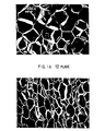
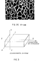
- Figures lA, B, C and 2A, B, C are photomicrographs (magnification: 50x) of the one- and two-directionally flexibilized foam of preferred Examples 123 and 223 of the present invention showing the closed cell structure as view in the X-, Y-and Z- axial directions defined in Figure 3.
- the flexibilized foams of this invention are characterized by an anisotropic cell wall structure in which the wrinkles in the cell wall are directionally oriented.
- wrinkles in the cell wall observed in the X -axial direction ( Figure lA) are significantly fewer than those observed in the Y- and Z-axial directions ( Figures 1B and 1C).
- the cell walls are generally less wrinkled in the X-axial and Z-axial directions ( Figures 2A and 2C) than in the Y-axial direction ( Figure 2B).
- the coordinates dimensions X , Y and Z correspond to the length in the machine or extrusion direction, thickness and width of the foam sheet, respectively.
- anisotropic wrinkles in combination with the properties of the formulated resin forming the cell walls membranes, the cell size and shape, and the foam density are important parameters of the flexibilized foam. Also such physical properties as axial elongation at rupture and water vapor permeability provide fairly accurate indication of the type, location and distribution of the anisotropic wrinkles.
- the present invention is greatly influenced by the properties of the initial expanded foam sheet or planks.
- the synthetic resin foams used herein must be of substantially closed-cell structure and include foams expanded by extrusion as well as those molded from expandable beads.
- most preferable are extrusion-expanded foam boards of substantially rigid, closed-cell structure.
- density, cell size, compression strength, and thermal resistance which in turn depend on the synthetic resin polymers used in making the initial foams.
- Suitable are synthetic resins mainly composed of styrene, vinyl chloride, vinylidene chloride, methyl methacrylate or nylon including copolymers thereof and physical blends of these resins.
- resins containing as a major component styrene or a styrenic monomer such as a-methyl styrene and o-, m-, p-vinyltoluene and chlorostyrene.
- copolymers of styrene or styrenic monomers and other monomers copolymerizable therewith such as acrylonitrile, methacrylonitrile, methyl acrylate, methy methacrylate, maleic anhydride, acrylamide, vinylpyridine, acrylic acid, and methacrylic acid.
- polystyrene resins consisting essentially of only polymerized styrene and, most preferable polystyrene resins containing 0.3 percent by weight or less of residual styrene monomer and 0.5 to 1.5 percent by weight of styrene oligomers, primarily dimer and trimer.
- Polystyrene resins containing such quantities of styrene monomer and styrene trimer provide expanded foams having particularly uniform distribution of density and cell size as well as improved resistance to repeated compression. Foams from such polystyrene resins are especially well suited for one- and two-directional flexibilization.
- rubber may be blended with such monomers before polymerization or added to the system after polymerization. Further, the foregoing resins may be blended with other polymers so long as the desirable properties of the styrene resins are not adversely affected.
- the synthetic resin foam have (1) a bulk density of about 20 to 100 kg/m 3 , and preferably about 20 to 60 kg/m 3 for one-directional flexibilization (2) a Y -direction cell size of about 0.05-1.0 mm, and (3) a Y-axial compressive strength of at least 1.8 kg/cm .
- Y -axial cell size y a group of flexibilized foams having varied foam densities and Y-axial cell sizes were evaluated for Y-axial compressive strength as a parameter of creep resistance, X-axial and Z-axial tensile strengths as parameters of breakage or rupture resistance of the foams in use, variations in the X -axial and Z-axial tensile strengths as parameters of the uniformity of performance or quality, and Y -axial thermal conductivity.
- foams of the present invention must have a bulk density of about 20 to 100 kg/m 3 , average y cell size of 0.05 to 1.0 mm and average cell size ratios y/x and y/z > 1.05. More preferably the foams must be constructed substantially of cells having the major axis thereof more definitely disposed along the Y-axis with the axial average cell axial size ratios y / x and y / z are 1.10 to 4.0. If the average axial cell size ratios y / x and y / z exceeds 4, the balance between the dimensional stability, linear expansion coefficient and the tensile strength will be lost.
- Synthetic resin foams having the required bulk density and anisotropic cell structure and size can be flexibilized by compression in one or two axial directions as described in Nakamura U.S. 3,159,700 to provide the high water vapor barrier and other properties desired for low temperature and cryogenic insulation. However, carefully controlled conditions are required.
- Figures 4 and 5 show schematic diagrams of suitable compression equipment of flexibilizers.
- the flexibilizer of Figure 4 there are provided infeed rollers 1, 2 and outfeed rollers 3, 4 spaced longitudinally from each other.
- the flexibilizer shown in Figure 5 is provided with infeed belts 9, 10 and outfeed belts 11, 12 which are also spaced longitudinally from each other. These paired rollers or belts hold the expanded foam securely.
- the reference numerals 5, 6 in Figure 5 and the reference numerals 13, 14 in Figure 4 indicate foam holding pressure means which should be controlled accurately because the foam will undergo a significant thicknesswise compression if the pressure is too strong.
- the infeed rollers or belts are driven somewhat faster than the second (outfeed) pair so that the foam is compressed in the longitudinal direction in the gap between the infeed and outfeed rollers or belts.
- the foam is normally compressed first in the longitudinal (X-axial) direction.
- the one-directionally flexibilized sheet can be subjected to compression in another direction at right angle to the longitudinal direction, namely, in the lateral (Z-axial) direction to provide a more flexible sheet which can assume a compound curvature.
- the flexibilization conditions must be carefully selected and controlled. Particularly important are:
- a uniform quality for the initial expanded foam sheet is required since the foams are mechanically compressed for flexibilization one-direction at axis by axis a time, e.g., X-axially first and then Z-axially, while being held squeezedly Y-axially. Thus it is necessary that the foams have minimum variation in mechanical properties, especially compressive strength throughout the sheet.
- foam sheets ranging from 10 mm to 300 mm in thickness have been flexibilized without significant loss in Y-axial compressive strength, water vapor barrier properties and other desired properties.
- the flexibilizer of Figure 5 is preferred. Elongation of foam processed with this flexibilizer can be controlled by the spacing between the infeed and outfeed belts.
- the compression distance D should be about 300 mm at the maximum, and preferably 200 mm or less, with a compression duration of at least one second. Line speeds of 5 to 40 m/min can be achieved with good results.
- flexibilized sheets can be laminated in desired configurations using a small amount of an adhesive applied sporadically to minimize the effect of the adhesive on the properties of the laminated foams.
- Flexibilization essential herein is achieved by the controlled introduction of anisotropically oriented wrinkles in the foam cell walls in a manner that does not unduly weaken the integrity of the foam or crack the cell walls and cause loss of thermal insulation and water vapor barrier properties. Since the foam cells are very small and have polyhedral shapes, it is very difficult to define the location of such wrinkles accurately in terms of cell shape and structure. However, the Y -axial water vapor permeability of the flexibilized foam indicates cracking or breakage of the cell walls. Also the percentage elongation at rupture in the three axial directions is a measurable parameter of the extensibility, location and distribution of the wrinkles. Typical results are given in the Examples, and particularly Tables 3 and 4.
- the foams contemplated by the present invention must have a Y-axial water vapor permeability Py equal to or smaller than 1.5 g/m 2 ⁇ hr to prevent or minimize deterioration in thermal-insulating properties over long use. More preferably, the water vapor permeability should be 1 . 0 g/m 2 ⁇ hr or less.
- the elongations at rupture in the three axial directions are useful parameters of extensibility, location and distribution of wrinkles and suitability for applications involving such severe conditions as encountered in liquid nitrogen storage tanks.
- Evaluation of the variations in the X-axial and Z-axial elongations at rupture shows the uniformity of the extensibility throughout the foam while the change in Y-axial thermal conductivity with time reflects loss of thermal-insulating properties from moisture absorption after prolonged use under Y-axial loads.
- cryogenic tests at about -160°C and -196°C show the crack resistance of the foam when used as thermal-insulation for liquefied natural gas and nitrogen tanks.
- the preferred polystyrene foams exhibit excellent properties as cryogenic insulation even without cladding reinforcement. Their bendability and thermoformability are particularly advantageous for field construction.
- two or more such foams may be bonded to form foam logs with biaxial extensibility. Also, they may be clad with metal foils or they may be combined with synthetic resin films having high gas barrier properties.
- the present invention also provides improved synthetic resin foams which can be applied to small--diameter pipes by adjusting the extensibility of the foams in the bending direction in accordance with the pipe outside diameter and the foam thickness.
- Other tests with 114 mm outside diameter pipes confirmed the applicability of the one- and two-dimensionally flexibilized foam sheet to a variety of curved surfaces including pipes and cylindrical and spherical tanks regardless of curvature.
- the polystyrene resins used for the extruded foam sheets were selected from commercial stock after analysis for residual volatiles (primarily styrene and ethylbenzene) and oligomers (styrene dimer and trimer) by gas chromatography using a flame ionization detector.
- the resin is dissolved in methyl ethyl ketone, the polymer precipitated with methanol, and the supernatant liquid analyzed.
- These resins had an intrinsic viscosity of about 0.83 measured in toluene solution at 30°C.
- the polymers were expanded into a rigid, substantially closed-cell foam with an extrusion-foaming system composed of a screw extruder, blowing agent blending feeder, cooler and board-forming die. More specifically, a mechanical blend of 100 parts of the polystyrene resin, 2 parts of a flame retardant and 0.03 to 0.1 part of a nucleator is continuously fed into the extruder with 12 to 17 parts of a 50/50 mixture of dichlorodifluoromethane/methyl chloride as a blowing agent. The thermoplastic mixture is kneaded under pressure, cooled to an extrusion temperature of about 90° to 118°C and then extruded through a die and expanded into a foam.
- an extrusion-foaming system composed of a screw extruder, blowing agent blending feeder, cooler and board-forming die. More specifically, a mechanical blend of 100 parts of the polystyrene resin, 2 parts of a flame retardant and 0.03 to 0.1 part of a nucle
- the extrusion conditions were controlled so that the foam was about 110 mm x 350 mm in cross-section and the axial cell size ratios v/x and y / z were about 1.1 to 1.25 and 1.1 to 1.17, respectively.
- the Y-axial cell size and bulk density D were varied in the range of 0.07 to 1.6 mm and about 21.5 to 77 kg/m , respectively.
- Foams lighter than about 21 kg/m 3 were subjected to secondary expansion by exposure to steam at 100°C for 2 to 6 minutes. The resultant foams have a bulk density of about 15.5 to 20 kg/m 3 . Analysis showed essentially no loss of residual volatiles or oligomers in the extrusion process.
- the resulting flexibilized foam planks are then evaluated by standard test procedures. Individual test results are rated on a general scale as: and then an overall composite evaluation rating is made on the scale:
- Standard test samples normally a 50 mm cube or a 25 mm x 100 mm x 100 mm sheet are cut from the center parts of the skinless foam board and their weight (g) and volume (cm 3 ) determined and the foam density calculated from the average of at least three specimens.
- the density variation calculated by the formula: provides a useful measure of foam uniformity:
- the X-axial, Y -axial and Z-axial average cell sizes x , y and z in terms of the coordinates of Figure 3 are measured by the method of ASTM D-2842 using nine specimens cut in the prescribed manner. Then as parameters of cell shape, the ratios of the Y -axial average cell size y versus X -axial and Z-axial average cell sizes x and z are calculated.
- the average cell size variation provides a measure of foam uniformity on the following evaluation scale:
- each specimen is subjected to X-axial tensile strength test with a jig or loading fixture attached to each end.
- the measured strength S 1 through s 12 are averaged and the tensile strength variation is calculated as follows:
- the Z-axial average tensile strength and variation thereof are measured on another twelve specimens.
- a flexibilized foam board is cut into specimens each 200 mm square and 25 mm thick. Each specimen is then aged in a chamber partially filled with water and held at 27°C. The specimen is secured in the chamber about 30 mm above the water surface and a cold plate cooled to 2°C by recirculated cooled water is brought into tight contact with the top surface of the specimen. After aging for 14 days, the specimen is taken out and its surface is wiped lightly with gauze. The thermal conductivity ⁇ ' of the aged specimen is measured in accordance with ASTM C-518 and the ratio of ⁇ ' to the initial thermal conductivity ⁇ of the specimen before aging is calculated.
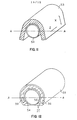
- Three 20 mm x 100 mm x 1750 mm specimens were prepared from a flexibilized foam board and wound around a stainless steel pipe 36 and their opposite end faces ( YZ faces) were butt-welded together as shown at 40, 41 and 42 in Figure 10.
- the the pipe specimens were quickly immersed in a cryostat filled with liquid nitrogen so that all specimens were well under the liquid surface. After being immersed for 5 hours, they were taken out of the cryostat and left at a room temperature for 5 hours. After 4 cycles of such treatment, the three specimens were carefully observed for any visual changes including cracks, fractures or ruptures.
- Each cryogenic test panel 34 is placed in a liquid nitrogen cooled cryostat box having an internal temperature controlled to -160°C ⁇ 5°C by controlled addition, gasification and diffusion of liquid nitrogen. After 5 hours, the test panel is quickly removed and left at room temperatures for about 1 hour. This process is repeated 4 cycles. After the last cycle, the test panel is visually checked for cracks in the four exposed faces of the foam specimen. Then one hour after removal from the cryostat, the plywood covers are removed with a slicer. Then a 10 mm thick slice of the foam is cut from the top surface and a mixture of a surfactant and colorant in water is applied to the surfaces of the cut foam to show any cracks formed therein.
- a cryogenic box partially filled with a liquid nitrogen is used.
- the plywood faced test panels are submerged in the liquid nitrogen and placed on triangular steel supports fixed to the bottom of the box.
- a steel weight precooled in liquid nitrogen is placed on the test panel top, and the panel held immersed for 30 minutes. Then the test panel is taken out and left at room temperature for one hour under forced ventilation. After repeating the foregoing process for four or more cycles, check is made for surface and internal cracks in the manner described above in test B(1).
- Thermoformability The flexibilized foam pieces are bent to the outside curvature of the steel pipe 54 about 114 mm in outside diameter with its Z-axis disposed along the axis of the pipe. Markings are put on the cut edge of the pipe 54 diameterically oppositely along the center line A - A shown in Figure 12.
- the bent specimen 56 is then totally covered with a galvanized, 0.3 mm thick sheet iron 55 and the opposite side ends of the foam specimen held with tensioning bands 57. Then the covered specimen 56 is placed in a hot-air oven with the tensioning bands 57 down and heated at 85°C for 45 minutes. After being removed from the oven, the specimen is cooled at room temperature for two hours. Then, the galvanized cover 55 is removed and the gaps 58 and 59 from the outer ends of the foregoing markings to the intersections of the center line A - A and the inner wall of the specimen 56 are measured and rated as follows:
- Thermal Insulation Test Pieces of flexibilized foam cut to a 37.5 mm x 200 mm x 500 mm size are thermoformed as above in two layers and then cut Z-axially to provide inner and outer semicylindrical thermal insulation covers for a 114 mm o.d. pipe.
- the test cover pieces are then fit to a 114 mm o.d. stainless steel pipe about 800 mm long with flanges at each end and secured with a cryogenic polyurethane adhesive.
- the joints of the outer covers are staggered from those of the inner cover.
- the entire section is then coated with a 2.5 mm thick waterproof layer of polyurethane mastic. After 4 days aging, the covered pipe is connected to a cryogenic test line and filled with liquid nitrogen.
- the interior of the stainless steel pipe is maintained at -196°C for 6 hours. Thereafter, the liquid nitrogen is discharged and the covered pipe left for 12 hours at 23°C and 80% R.H.
- the foregoing test cycle is repeated four times while observing the surface conditions of the water-proof layer 66 including water condensation and icing.
- foam planks were prepared for one-directional flexibilization.
- the extrusion conditions were controlled to give a foam sheet about 110 mm x 350 mm in cross-section with a bulk density of about 21.5 to 60 kg/m 3 . Skins were removed from each of the foams and the resulting foam board was cut into three smaller planks each 100 mm square and 4,000 mm long.
- the foam planks were flexibilized by compression in the machine direction (X-axis) using the equipment of Fig. 5 and the typical conditions described in the procedures above.
- the flexibilized foam planks of the preferred Examples 101-112 were evaluated for density, Y-axial cell sizes, cell shapes represented by y / x and y/z, compression strengths (Y-axial and Z-axial), X-axial tensile strengths and elongation at rupture with the results shown in Table 1.
- the axial cell size ratios y / z were in the range of 1.00 to 1.25.
- the foam bulk densities were plotted on the chart Fig. 6A against the Y -axial average cell sizes y .
- the coordinates representing the foam specimens satisfying the objects of the present invention are marked with o, while those representing the specimens not satisfying the objects of the present invention are marked with X.
- the foams as intended by the present invention must have such Y -axial average cell sizes y and bulk densities D that fall in the pentagonal domain defined by five coordinates (1.0, 43), (1.0, 20), (0.05, 24), (0.05, 60) and (0.1, 60) and, more preferably, in the tetragonal domain defined by the coordinates (0.8, 42), (0.8, 23), (0.07, 26) and (0.07, 57).
- the bulk densities D and Y -axial cell sizes y of these foams satisfy the following formula:
- foam planks were prepared about 110 mm x 350 mm in cross-section, axial cell size ratios y / x and y / z about 1.1 to 1.25 and 1.1 to 1.17, respectively, while the Y-axial cell size and bulk density d are varied in the range of 0.07 to 1.6 mm and 21.5 to 77 kg/m 3 , respectively.
- Those foams lighter than about 21 kg/m 3 are subjected to secondary expansion by exposing them to steam at 100°C for 2 to 6 minutes resulting in a bulk density of about 15.5 to 20 kg/m 3 .
- flexibilized foam planks of the Preferred Examples 201-212 and Reference Examples R201-206 having almost constant cell shapes with the axial cell size ratios y/x and y/z ranging from 1.2 to 1.4 are obtained. Then these flexibilized planks are evaluated by the standard procedures with typical results shown in Table 2.
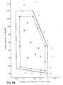
- the bulk densities D are plotted on the chart of Fig. 6B against the Y-axial average cell sizes y , in which the coordinates representing the foam specimens evaluated as excellent and good in Table 2 are marked with O and o, respectively, while those evaluated as unacceptable being marked with X.
- the foams as intended by the present invention must have such y-axial average cell sizes y in mm and bulk densities D in kg/m 3 that fall in the pentagonal domain defined by five coordinates (1.0, 55), (0.25, 100), (0.05, 100), (0.05, 26.5) and (1.0, 20) and, more preferably, in the pentagonal domain defined by five coordinates (0.8, 55), (0.25, 93), (0.07, 93), (0.07, 28.5) and (0.8, 23.5).
- the foams contemplated by the present invention must have such a foam density D (kg/m ) and Y-axial average cell size y (mm) that satisfy the following formula:
- thermoplastic foam sheets are aged for at least several weeks before use to stabilize the foam structure.
- flexibilized foam for cryogenic insulation it was discovered that the age of the extruded foam at the time of compression flexibilization profoundly influenced the resulting foam properties.
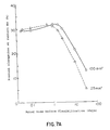
- Figure 7A shows the relation between X-axial elongation at rupture Ex of the flexibilized foams and the aging period of the initial foam sheet after extrusion
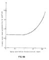
- Figure 8A shows the relation between water vapor permeability and the aging period before flexibilization. It is evident that to obtain the improved elongation and water vapor barrier properties intended by the present invention, it is necessary that the aging period for the foams prior to compression flexibilization be not more than 10 days (240 hrs) and more preferably, 3 days (72 hrs) or less.
- Figure 7B shows a relation between the X-axial percentage elongation at rupture Ex of two-directionally flexibilized foams and the aging time of the extruded foam planks. Note that aging affects the X-axial and Z-axial percentage elongations at rupture substantially equally.
- the initial fresh foam planks had a density of about 27 kg/m , thickness of about 100 mm, and X, Y-and Z-axial average cell sizes of about 0.55 mm, 0.72 mm and 0.58 mm, respectively. After being cut to a thickness of 25 mm, the foams were subjected to one cycle of 37 percent compression x-axially first and then Z-axially at varied aging times.
- the Z-axial percentage elongations at rupture Ez ranges from about 80 to 90 percent of the X-axial percentage elongation at rupture Ex.
- the axial percentage elongations at rupture are representatively given as the X-axial percent-elongation at rupture Ex.
- Fig. 8B shows a relationship between the water vapor permeability Py of flexibilized foams and the aging period of the material foams after expansion thereof.
- the foam planks have the same density and axial average cell sizes as those above.
- Test pieces about 25 mm thick were cut and subjected to 20-37 percent compression applied one to three times in each direction.
- the resulting foams had an X-axial percentage elongation at rupture Ez of about 20 percent and Z-axial percentage elongation at rupture Ez of about 16 percent.
- the foam should be flexibilized while fresh, i.e., within 10 days or more preferably 3 days of extrusion and/or expansion. This applies especially to relatively thin foams as represented by the 25 mm thick samples used in the preceding experiments.
- the optimum time within the range of about 0.25-240 hours will, of course, depend on the specific properties of the initial foam and the desired results.
- Critical for low temperature insulation is the ability of the foam to be an effective barrier to the transfer of water vapor from the outer to inner surface of the insulation.
- flexi- bilizable foam planks were expanded from PS Resin A under controlled conditions so that the resultant foams had densities D in the range of about 22.5 to 51 kg/m 3 , Y-axial cell sizes y in the range of about 0.07 to 1.0 mm and axial cell size ratios y / x and y / z of about 1.35 to 2 and about 1.1-1.3, respectively. Then the resultant foam planks were cut to 100 mm square and 4,000 mm long and after aging for one day were compressed X-axially. Typical properties including water vapor permeability for these flexibilized foams are given in Table 3.
- the flexibilized foam of the present invention must have a water vapor permeability of 1.5 g/m 2 ⁇ hr or lower as determined by the water method of ASTM C-355.
- Figures 1A, B and C are photomicrographs (magnification: 50x) of the polystyrene foam of the preferred example 123 showing closed cells distributed as viewed in the X-, Y- and Z-directions shown in Fig. 3.
- the flexibilized foams of the present invention have a unique structural anisotropy in which wrinkles in the cell walls observed in the YZ -plane (Fig. 1A) are significantly fewer than those observed in the XZ- and XY planes (Fig. 1B and 1C). Since the foam cells are very small and have polyhedral shapes, it is very difficult to express the distribution and locations of such wrinkles accurately.
- con- ,sidering the relations between Ex, E and the Y-axial water vapor permeability Py with reference to Fig. 1, these relationships provide fairly accurate structural parameters of the wrinkles including their type, location and distribution.
- Example 1 foam planks having the same cross--sections were extruded and expanded with a density of 27 kg/m 3 or 50 kg/m 3 and Y-axial average cell size of 0.61 mm or 0.11 mm with y / x of 1.20 or 1.15 and y / z of 1.25 or 1.20. These foam planks were compressed for flexibilization X-axially first and then Z -axially by using the equipment as shown in Fig. 5. Then the foam densities D and other properties including the Y-axial water permeability Py of the thus biaxially-flexibilized foams are measured. Also, the changes in Y-axial thermal conductivity as well as the X-axial and Z-axial cryogenic resistance at -160°C and -196°C are observed. Typical results are shown in Table 4.
- Table 4 shows that the foams of this invention must have a Y -axial water vapor permeability Py equal to or smaller than 1.5 g/m 2 ⁇ hr to prevent or minimize deterioration in thermal-insulating properties over a long period of use. More preferably, the water vapor permeability should be 1.0 g/m 2 ⁇ hr or smaller to secure a higher level of thermal-insulation.
- the preferred foams of the present invention must also satisfy the following conditions:
- Fig. 2A, B and C are photomicrographs (magnification: 50x) of the flexibilized polystyrene foam of Preferred Example 223 showing the closed cells viewed in the X , Y and Z directions shown in Fig. 3. Note that the foam is characterized by structurally anisotropic cell walls. Those visible in the YZ and XY planes shown in Fig. 2A and 2C are generally wavy only in one direction, namely in the Z-axial and X-axial directions respectively, but not in the Y-axial direction.
- Such anisotropically distributed cell wall wrinkles in combination with the foam density as well as with the sizes and shapes of cells are important structural parameters of the foams of the present invention, in view of the aforementioned relationship between Ex and Ez, the ratios of axial percentage elongations at rupture (Ex/Ey, Ez/Ey) and Y-axial water vapor permeability that represent the distribution and directions of such wrinkles..
- Table 5 shows the results of experiments on still another group of the preferred examples of the present invention and several reference foams. Since these evaluation items are substantially representative of the bendability, applicability to curved surfaces, adhesion workability, cryogenic insulating properties and other characteristics practically required to such foams, Table 5 does give overall evaluation for practical applicabilities of such foams.
- two or more such foams may be bonded so that the resultant foam logs show biaxial extensibility or they may be clad with metal foils or they may be combined with synthetic resin films having high gas barrier properties.
- foams namely the foams of preferred examples 222-225 and of the references R221, R223-225 are appplied, respectively, onto a steel pipe of about 114 mm in outside diameter as a typical representative of cylindrical pipes having a very large curvature.
- the foams were sliced to a thickness of 25, 37.5 or 75 mm and applied in one, two or three layers to obtain an overall thickness of 75 mm.
- the longitudinal and circumferential seams of the semicylindrical foams sections applied in layers are butted, while those of the foam sections 77 mm thick are shiplapped.
- the synthetic resin foams of the present invention having larger extensibility in two axial directions show excellent bendability, thermoformability and applicability to pipes having small diameters. They can be easily applied to such small-diameter pipes and can be easily thermoformed to their bent shapes. Further, because of substantial freedom from crack formation in bending operation or under cryogenic conditions, the synthetic resin foams according to the present invention can provide excellent cryogenic thermal-insulating materials free from moisture condensation even at -196°C which are generally applicable to pipes, cylindrical and spherical tanks.
- the reference foams compressed only X-axially or Z-axially have satisfiable bendability and thermoformability, they are not entirely satisfactory as cryogenic thermal-insulation because they may break under cryogenic conditions due to cracks spreading circumferentially of the pipe or in other directions. Such cracks form because these foams do not have sufficient extensibility to absorb stresses generated by sudden changes between the room and cryogenic temperatures.
- the improved flexibilization process is applicable to a variety of thermoplastic resin foams, both extruded and expanded.
- PS Resin A is a thermally polymerized polystyrene resin having an intrinsic viscosity of about 0.83 dissolved in toluene at 30°C and containing 0.20 weight percent residual volatiles including styrene monomer and 0.87 weight percent oligomers including styrene trimer. Blends with other polystyrene resins richer in residual styrene monomer and trimer were flexibilized with typical results shown in Table 7. For such thermally polymerized polystyrene resins, preferred resins for the flexibilized foams are those containing 0.3 weight percent or less of residual volatiles including styrene monomer and 0.5-1.5 weight percent of styrene oligomers including trimer.
- the present invention is applicable also to foams expanded from polyvinyl chloride resins including blends thereof with inorganic materials, methyl methacrylate and the like resins other than polystyrene, and the resulting.flexibilized foams satisfy the requirements of the present invention.
- a batch of prefoamed polystyrene beads having a bulk density of 11.6 kg/m 3 is placed in a mold, and steam is heated for about 40 seconds under pressure of 3 kg/cm 2 .
- the resulting foam was aged at about 70°C for 12 hours. It had a density of 10.9 kg/m with x of 0.33 mm, y of 0.31 mm and z of 0.32 mm.
- Three 350-mm cubes are cut out from its central portion by means of an electrically-heated wire cutter.
- One sample was flexibilized X-axially by compression to 90 percent of its original volume by applying 40 kg/cm 2 pressure with a 50-ton press. The compression was repeated continuous six times by relieving the pressure immediately after its application.
- the compressed foam has the size of 350 x 350 x 262 (mm) with a density of 1 4 .5 k g /m 3 .
Landscapes
- Engineering & Computer Science (AREA)
- Mechanical Engineering (AREA)
- Manufacture Of Porous Articles, And Recovery And Treatment Of Waste Products (AREA)
- Molding Of Porous Articles (AREA)
- Extrusion Moulding Of Plastics Or The Like (AREA)
Applications Claiming Priority (2)
| Application Number | Priority Date | Filing Date | Title |
|---|---|---|---|
| JP55690/81 | 1981-04-15 | ||
| JP56055690A JPS6056096B2 (ja) | 1981-04-15 | 1981-04-15 | スチレン系樹脂発泡体 |
Publications (2)
| Publication Number | Publication Date |
|---|---|
| EP0062882A2 true EP0062882A2 (fr) | 1982-10-20 |
| EP0062882A3 EP0062882A3 (fr) | 1985-08-07 |
Family
ID=13005891
Family Applications (1)
| Application Number | Title | Priority Date | Filing Date |
|---|---|---|---|
| EP82102919A Withdrawn EP0062882A3 (fr) | 1981-04-15 | 1982-04-05 | Flexibilisation directionnelle d'une feuille en mousse thermoplastique expansée pour isolation à basse température |
Country Status (2)
| Country | Link |
|---|---|
| EP (1) | EP0062882A3 (fr) |
| JP (1) | JPS6056096B2 (fr) |
Cited By (7)
| Publication number | Priority date | Publication date | Assignee | Title |
|---|---|---|---|---|
| EP0084862B1 (fr) * | 1982-01-22 | 1985-06-26 | The Dow Chemical Company | Appareil pour l'amélioration de la flexibilité de résine synthétique expansée |
| EP0212884A3 (fr) * | 1985-07-30 | 1988-07-20 | The Dow Chemical Company | Panneau partiellement flexibilisé en mousse plastique extrudée et son procédé de fabrication |
| EP0561216A1 (fr) * | 1992-03-19 | 1993-09-22 | BASF Aktiengesellschaft | Plaques de mousse avec des propriétés thermo-isolantes améliorées et méthode pour les fabriquer |
| EP0641635A1 (fr) * | 1993-09-08 | 1995-03-08 | BASF Aktiengesellschaft | Procédé de production de plaques de mousse de propriétés thermo-isolantes améliorées |
| EP0754720A1 (fr) * | 1995-07-15 | 1997-01-22 | Hüls Aktiengesellschaft | Corps isolant |
| WO2000018557A1 (fr) * | 1998-09-28 | 2000-04-06 | National Research Council Of Canada | Production de mousses par nucleation induite par contraintes |
| WO2010077516A3 (fr) * | 2008-12-17 | 2010-08-19 | Dow Global Technologies Inc. | Procédé continu de fabrication d'un article en mousse |
Families Citing this family (1)
| Publication number | Priority date | Publication date | Assignee | Title |
|---|---|---|---|---|
| US4455272A (en) * | 1982-03-29 | 1984-06-19 | Standard Oil Company (Indiana) | Method of extruding a polystyrene foam using both a physical blowing agent and water |
Family Cites Families (5)
| Publication number | Priority date | Publication date | Assignee | Title |
|---|---|---|---|---|
| CH308279A (de) * | 1951-11-10 | 1955-07-15 | Lonza Ag | Zellkörper mit gefalteten Zellwänden und Verfahren zu dessen Herstellung. |
| US3159700A (en) * | 1962-05-31 | 1964-12-01 | Dow Chemical Co | Flexibilizing rigid foams |
| US3191224A (en) * | 1962-05-31 | 1965-06-29 | Dow Chemical Co | Flexibilizing rigid foams |
| GB1220155A (en) * | 1967-08-29 | 1971-01-20 | Toray Industries | Modified cellular material |
| GB1272575A (en) * | 1968-04-04 | 1972-05-03 | Ronald Davey Janes | Soft flexible expanded synthetic resins incorporating reinforcement and flexible coatings |
-
1981
- 1981-04-15 JP JP56055690A patent/JPS6056096B2/ja not_active Expired
-
1982
- 1982-04-05 EP EP82102919A patent/EP0062882A3/fr not_active Withdrawn
Cited By (8)
| Publication number | Priority date | Publication date | Assignee | Title |
|---|---|---|---|---|
| EP0084862B1 (fr) * | 1982-01-22 | 1985-06-26 | The Dow Chemical Company | Appareil pour l'amélioration de la flexibilité de résine synthétique expansée |
| EP0212884A3 (fr) * | 1985-07-30 | 1988-07-20 | The Dow Chemical Company | Panneau partiellement flexibilisé en mousse plastique extrudée et son procédé de fabrication |
| EP0561216A1 (fr) * | 1992-03-19 | 1993-09-22 | BASF Aktiengesellschaft | Plaques de mousse avec des propriétés thermo-isolantes améliorées et méthode pour les fabriquer |
| EP0641635A1 (fr) * | 1993-09-08 | 1995-03-08 | BASF Aktiengesellschaft | Procédé de production de plaques de mousse de propriétés thermo-isolantes améliorées |
| US5520873A (en) * | 1993-09-08 | 1996-05-28 | Basf Aktiengesellschaft | Production of foam boards having improved sound insulation properties |
| EP0754720A1 (fr) * | 1995-07-15 | 1997-01-22 | Hüls Aktiengesellschaft | Corps isolant |
| WO2000018557A1 (fr) * | 1998-09-28 | 2000-04-06 | National Research Council Of Canada | Production de mousses par nucleation induite par contraintes |
| WO2010077516A3 (fr) * | 2008-12-17 | 2010-08-19 | Dow Global Technologies Inc. | Procédé continu de fabrication d'un article en mousse |
Also Published As
| Publication number | Publication date |
|---|---|
| JPS57173140A (en) | 1982-10-25 |
| JPS6056096B2 (ja) | 1985-12-09 |
| EP0062882A3 (fr) | 1985-08-07 |
Similar Documents
| Publication | Publication Date | Title |
|---|---|---|
| US4510268A (en) | Directional flexibilization of expanded thermoplastic foam sheet for low temperature insulation | |
| CA1179463A (fr) | Feuille souple en mousse thermoplastique pour l'isolation thermique aux basses temperatures | |
| EP0185661B1 (fr) | Structure thermo-isolantes pour tuyauteries a basse temperature ou cryogeniques | |
| Marshall | Sandwich construction | |
| US20040109994A1 (en) | Polyester core materials and structural sandwich composites thereof | |
| EP0062882A2 (fr) | Flexibilisation directionnelle d'une feuille en mousse thermoplastique expansée pour isolation à basse température | |
| US5334337A (en) | Production of foam boards of high compressive strength using a blowing agent mixture | |
| KR0157309B1 (ko) | 연속 시트상 전자선 가교 발포체 | |
| Feichtinger | Test methods and performance of structural core materials-1. Static properties | |
| Noury et al. | On mixed-mode fracture of PVC foam | |
| US20260035168A1 (en) | Shipping container | |
| Bomberg | Scaling factors in aging of gas-filled cellular plastics | |
| JP3248991B2 (ja) | 新規の複合材料 | |
| CA1244336A (fr) | Ensembles calorifuges pour tuyauteries cyrogeniques ou basse temperature | |
| AU590713B2 (en) | Heat insulating structures for low-temperature or cryogenic pipings | |
| SE463769B (sv) | Kamouflagematerial av pvc-cellplast med slutna celler | |
| Bomberg et al. | Report on sprayed polyurethane foam with alternative blowing agents | |
| JPH0235664B2 (fr) | ||
| Whittaker | The mechanical behavior of microporous polyurethane foams | |
| JPH0247348B2 (fr) | ||
| Andersons et al. | Fracture toughness of PIR foams produced from renewable resources | |
| JPS59106793A (ja) | 低温配管断熱装置 | |
| JPS5920655A (ja) | 低温断熱用複合板 | |
| JPH0247346B2 (fr) | ||
| Clutlon et al. | Structure-Property Relationships in Thezmoplasttc foams |
Legal Events
| Date | Code | Title | Description |
|---|---|---|---|
| PUAI | Public reference made under article 153(3) epc to a published international application that has entered the european phase |
Free format text: ORIGINAL CODE: 0009012 |
|
| AK | Designated contracting states |
Designated state(s): AT BE DE FR IT NL SE |
|
| PUAL | Search report despatched |
Free format text: ORIGINAL CODE: 0009013 |
|
| RHK1 | Main classification (correction) |
Ipc: B29C 71/00 |
|
| AK | Designated contracting states |
Designated state(s): AT BE DE FR IT NL SE |
|
| 17P | Request for examination filed |
Effective date: 19850909 |
|
| 17Q | First examination report despatched |
Effective date: 19860402 |
|
| R17C | First examination report despatched (corrected) |
Effective date: 19870206 |
|
| STAA | Information on the status of an ep patent application or granted ep patent |
Free format text: STATUS: THE APPLICATION HAS BEEN WITHDRAWN |
|
| 18W | Application withdrawn |
Withdrawal date: 19871123 |
|
| RIN1 | Information on inventor provided before grant (corrected) |
Inventor name: TONOKAWA, HIROSHI Inventor name: NAKAMURA, MASAO |