EP0062925A1 - Lagerraum für Fahrzeugersatzrad - Google Patents
Lagerraum für Fahrzeugersatzrad Download PDFInfo
- Publication number
- EP0062925A1 EP0062925A1 EP82103149A EP82103149A EP0062925A1 EP 0062925 A1 EP0062925 A1 EP 0062925A1 EP 82103149 A EP82103149 A EP 82103149A EP 82103149 A EP82103149 A EP 82103149A EP 0062925 A1 EP0062925 A1 EP 0062925A1
- Authority
- EP
- European Patent Office
- Prior art keywords
- tire
- pan portion
- storage pan
- receptacle member
- side wall
- Prior art date
- Legal status (The legal status is an assumption and is not a legal conclusion. Google has not performed a legal analysis and makes no representation as to the accuracy of the status listed.)
- Granted
Links
- 239000000446 fuel Substances 0.000 description 18
- 230000002093 peripheral effect Effects 0.000 description 9
- 230000006378 damage Effects 0.000 description 5
- 239000006096 absorbing agent Substances 0.000 description 2
- 230000004308 accommodation Effects 0.000 description 2
- 230000001413 cellular effect Effects 0.000 description 2
- 239000006260 foam Substances 0.000 description 2
- 230000004048 modification Effects 0.000 description 2
- 238000012986 modification Methods 0.000 description 2
- 229920002635 polyurethane Polymers 0.000 description 2
- 239000004814 polyurethane Substances 0.000 description 2
- 230000035939 shock Effects 0.000 description 2
- 208000027418 Wounds and injury Diseases 0.000 description 1
- 230000006866 deterioration Effects 0.000 description 1
- 239000013013 elastic material Substances 0.000 description 1
- 238000010304 firing Methods 0.000 description 1
- 208000014674 injury Diseases 0.000 description 1
- 239000000463 material Substances 0.000 description 1
- 238000012827 research and development Methods 0.000 description 1
Images


Classifications
-
- B—PERFORMING OPERATIONS; TRANSPORTING
- B62—LAND VEHICLES FOR TRAVELLING OTHERWISE THAN ON RAILS
- B62D—MOTOR VEHICLES; TRAILERS
- B62D43/00—Spare wheel stowing, holding, or mounting arrangements
- B62D43/06—Spare wheel stowing, holding, or mounting arrangements within the vehicle body
- B62D43/10—Spare wheel stowing, holding, or mounting arrangements within the vehicle body and arranged substantially horizontally
Definitions
- Fig. 1 shows a representative example of the prior-art spare-tire storage arrangement in such an automotive vehicle.
- the vehicle body has a floor panel structure 1 formed with a generally barrel-shaped, tire-storage pan portion 2 which is usually located below the rear luggage compartment of the vehicle body.
- the tire- storage pan portion 2 is downwardly sunk from the upper horizontal plane of the floor panel structure 1.
- a spare tire T is housed within this tire-storage pan portion 2 and is releasably fixed to the bottom wall of the tire-storage pan portion 2 by suitable clamping means 3 when the tire is not in use.
- the automotive vehicle having such a spare-tire storage arrangement may further have a fuel storage tank 4 fixedly attached to the underside of the floor panel structure 1 for the purpose of alleviating the strict space requirement of the vehicle and to prevent leakage of fuel into the vehicle body in the event of, for example, an accident.
- the fuel storage tank 4 thus supported by the floor panel structure 1 is usually located in front of the tire-storage pan portion 2.
- Fig. 2 of the drawings shows a conventional spare-tire storage arrangement used for the storage of such a temporary-use spare tire T'.
- the temporary-use spare tire T' housed in the tire-storage pan portion 2 is compactly stored in the pan portion 2 so that only a slight annular gap is formed between the spare tire T' and the side wall 2a of the tire-storage pan portion 2. If the vehicle having the temporary-use spare tire T' stored in such a condition in the tire-storage pan portion 2 encounters a forward collision at the rear end thereof, the spare tire T' will act as a shock absorber which lends itself to preventing the pan portion 2 from causing damages to the fuel storage tank 4, which is therefore protected from causing leakage of fuel therefrom.
- the temporary-use spare tire T' housed therein is radially spaced apart inwardly from the side wall 2a of the pan portion 2.
- a considerable annular gap is formed horizontally between the side wall 2a of the tire-storage pan portion 2 and the outer perimeter of the tread portion of the spare tire T' housed in the pan portion 2 as indicated at 5 in Fig. 2.
- the tire-storage pan portion 2 will act as a shock absorber which lends itself to preventing the pan portion 2 from causing damages to the fuel storage tank 4, which is therefore protected from causing leakage of fuel therefrom.
- a suitable upper lid member of, for example, a hardboard is placed atop the concavity in the tire-storage pan portion 2 as indicated at 6 in Fig. 2 so as to define the bottom of the luggage compartment above the spare tire T' positioned in the pan portion 2. If a temporary-use spare tire T' is stored in the tire-storage pan portion 2 thus closed at the upper end by the lid member 6, there is a vacant space formed vertically between the lower face of the lid member 6 and the spare tire T' in the pan portion 2 as indicated at 5' in Fig. 2.
- the present invention contemplates provision of an improved spare-tire storage arrangement which will meet these mutually incompatible requirements of a prior-art spare-tire storage arrangement of the described basic nature.
- Figs. 4 and 5 of the drawings shows a first preferred embodiment of a spare-tire storage arrangement according to the present invention.
- the spare-tire storage arrangement herein shown is basically similar to the prior-art spare-tire storage arrangement described with reference to Figs. 1 and 2.
- the body structure of an automotive vehicle provided with the spare-tire storage arrangement embodying the present invention also has a floor panel structure 1 formed with a generally barrel-shaped, tire-storage pan portion 2.
- the tire-storage pan portion 2 of the floor panel structure 1 is downwardly sunk from the upper horizontal plane of the floor panel structure 1 and has formed therein a concavity which is open upwardly and which is surrounded by a generally cylindrical side wall 2a.
- the tire-storage pan portion 2 is internally sized to be suitable for having a spare tire T (Fig. 1) of particularly the regular size snugly or closely received on the inner peripheral surface of its side wall 2a along or at least at some points of the outer perimeter of the tread portion of the tire T and is located below, for example, the rear luggage compartment of the vehicle body.
- the floor panel structure 1 thus formed with a tire-storage pan portion 2 further has supported a fuel storage tank 4 which is fixedly attached to the lower face of the floor panel structure 1 and which is located, for example, in front of the tire-storage pan portion 2 as shown.
- the spare-tire storage arrangement embodying the present invention comprises, in addition to such a tire-storage pan portion 2 of the floor panel structure 1, an also generally drum-shaped receptacle member 7 having an annular bottom wall portion 7a formed with a central aperture 8 and a generally cylindrical side wall portion 7b as will be better seen from Fig. 5 of the drawings.
- the receptacle member 7 is externally sized to fit the inner peripheral surface of the side wall 2a of the tire-storage pan portion 2, viz., has an outside diameter substantially equal to or slightly smaller than the inside diameter of the side wall 2a of the tire-storage pan portion 2 as will be seen from the illustration of Fig. 4.
- the receptacle member 7 is in its entirety formed with a concavity defined by the bottom wall portion 7a and side wall portion 7b thereof and is internally sized to be capable of having a temporary-use spare tire T' snugly received therein as will also be seen from the illustration of Fig. 4.
- the receptacle member 7 has its bottom wall portion 7a sized to have a thickness which is such that the concavity formed in the receptacle member 7 has a depth substantially equal to or slightly less than the width of a temporary-use spare tire T', and its side wall portion 7b sized to have an inside diameter substantially equal to or slightly smaller than the outside diameter of the spare tire T'.
- the bottom wall portion 7a of the receptacle member 7 accordingly has an upper face located above the upper or inner face of the bottom wall of the tire-storage pan portion 2 at a level substantially equal to the difference between the depth of the concavity in the tire-storage pan portion 2 and the width of a temporary-use spare tire T. Furthermore, the receptacle member 7 preferably has a height substantially equal to or not larger than the depth of the concavity in the tire-storage pan portion 2.
- the receptacle member 7 shaped and sized as above described is snugly received in the tire- storage pan portion 2 with the lower face of its bottom wall portion 7a held in close contact with the upper or inner face of the bottom wall of the tire-storage pan portion 2 and its side wall 7b held in contact with the inner peripheral surface of the side wall 2a of the pan portion 2.
- the receptacle member 7 is preferably constructed of an elastic material such as, for example, cellular foams of polyurethane so as to achieve a close fit particularly between the side wall 2a of the tire-storage pan portion 2 and the side wall portion 7b of the receptacle member 7.
- the spare-tire storage arrangement embodying the present invention further comprises suitable clamping means 3 for holding a temporary-use spare tire T' fixedly in position within the receptacle member 7.
- the clamping means 3 is composed of a bracket member 3a, clamping bolt 3b and a wing nut 3c.
- the bracket member 3a is located within the central aperture 8 in the receptacle member 7 and is securely attached to the upper or inner face of the bottom wall of the tire-storage pan portion 2.
- the clamping bolt 3b is secured to and extends upwardly from the bracket member 3a through the central aperture 8 in the receptacle member 7 and is engaged by the wing nut adjacent the upper end of the bolt 3b.
- the temporary-use spare tire T' to be housed within the tire-storage pan portion 2 is received in the concavity in the receptacle member 7 and is held in close contact with the annular upper or inner face of the bottom wall portion 7a of the receptacle member 7 along one side wall portion of the tire T' and with the inner peripheral surface of the side wall portion 7b of the receptacle member 7 along or at least at some points of the outer perimeter of the tread portion of the tire T'.
- the spare tire T' thus positioned within the concavity in the receptacle member 7 is securely yet detachably fixed to the bottom wall portion 7a of the receptacle member 7 with the wing nut 3c of the above mentioned clamping means 3 tightened to the wheel disc of the tire T'.
- a lid member 6 of, for example, a hardboard is placed on the floor panel structure 1 in such a manner as to cover the concavity in the tire-storage pan portion 2 so as to define a portion of the bottom of the luggage compartment above the tire-storage pan portion 2 as in the prior-art spare-tire storage arrangement shown in Fig. 2.
- the receptacle member 7 forming part of the embodiment of the arrangement above described with reference to Figs.
- Figs. 6 and 7 of the drawings show a second preferred embodiment of a spare-tire storage arrangement according to the present invention.
- the spare-tire storage arrangement herein shown is a modification of the embodiment hereinbefore described with reference to Figs. 4 and 5 and is adapted to eliminate only the vacant space 5' formed between the temporary-use spare tire T' housed in the tire-storage pan portion 2 and the lid member 6 positioned atop the concavity in the pan portion 2 as in the prior-art spare-tire storage arrangement shown in Fig. 2.
- the spare-tire storage arrangement shown in Fig. 6 comprises, in addition to the tire-storage pan portion 2 of the floor panel structure 1 of an automotive vehicle body, a disc-shaped or an annular receptacle member 7' formed with a central aperture 8 as will be better seen from Fig. 7 of the drawings.
- the receptacle member 7' is externally sized to fit the inner peripheral surface of the side wall 2a of the tire-storage pan portion 2, viz., has an outside diameter substantially equal to or slightly smaller than the inside diameter of the side wall 2a of the tire-storage pan portion 2 as will be seen from Fig. 6.
- the receptacle member 7' further has a thickness which is substantially equal to the difference between the depth of the concavity in the tire-storage pan portion 2 and the width of a temporary-use spare tire T' as will also be seen from Fig. 6.
- the receptacle member 7' shaped and sized as above described is snugly received in the tire-storage pan portion 2 with the lower face thereof held in close contact with the upper or inner face of the bottom wall of the tire-storage pan portion 2 and its outer peripheral surface held in close contact with the inner peripheral surface of the side wall 2a of the pan portion 2.
- the receptacle member 7' is also preferably constructed of, for example, cellular foams of polyurethane.
- the tire-storage pan portion 2 of the floor panel structure 1 constituting the spare-tire storage arrangement including the receptacle member 7' thus arranged is per se similar to its counterpart in the embodiment of Fig. 4.
- the temporary-use spare tire T' to be housed within the tire-storage pan portion 2 is received on the annular upper face of the receptacle member 7' along one side wall portion of the tire T' with the tread portion of the tire T' radially spaced apart inwardly from the side wall 2a of the tire-storage pan portion 2.
- the spare tire T' thus positioned on the receptacle member 7' is securely yet detachably fixed to the receptacle member 7' with the the clamping bolt 3b of the previously described clamping means 3 upwardly passed through the central aperture 8 in the receptacle member 7' and with the wing nut 3c of the clamping means 3 tightened to the wheel disc of the tire T'.
- a lid member (not shown) of, for example, a hardboard may also be placed on the floor panel structure 1 in such a manner as to cover the concavity in the tire-storage pan portion 2.
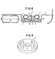
- Fig. 8 of the drawings shows a third preferred embodiment of a spare-tire storage arrangement according to the present invention.
- the spare-tire storage arrangement herein shown is a modification of the embodiment hereinbefore described with reference to Figs. 6 and 7 and is characterized by an annular receptacle member 7" formed with a central aperture 8 as will be better seen from Fig. 9 of the drawings.
- the receptacle member 7" in its entirety is shaped and sized similarly to the receptacle member 7' in the spare-tire storage arrangement embodying the present invention as described with reference to Figs. 6 and 7.
- the receptacle member 7" is thus also snugly received in the tire-storage pan portion 2 of the floor panel structure 1 with the lower face thereof held in close contact with the upper or inner face of the bottom wall of the tire- storage pan portion 2 and its outer peripheral surface held in contact with the inner peripheral surface of the side wall 2a of the pan portion 2.
- the receptacle member 7" is formed not only with the central aperture 8 but a suitable number of concavities 9 which are open upwardly as will be clearly seen from the illustration of Fig. 9.
- the concavities 9 thus formed in the receptacle member 7" are intended to serve as spaces to accommodate therein some repair tools (not shown) or the like to be used when, for example, the spare tire T' stored in the tire-storage pan portion 2 is to be exchanged with one of the tires in use on the vehicle.
- the concavities 9 formed in the receptacle member 7" as described above are shown provided as being two in number and each having a generally crescent- shaped cross section. Such arrangement of the concavities 9 in the receptacle member 7" of the embodiment shown in Fig. 7 is, however, merely for the purpose of illustration and may be changed and/or modified as desired.
Landscapes
- Engineering & Computer Science (AREA)
- Chemical & Material Sciences (AREA)
- Combustion & Propulsion (AREA)
- Transportation (AREA)
- Mechanical Engineering (AREA)
- Body Structure For Vehicles (AREA)
Applications Claiming Priority (2)
| Application Number | Priority Date | Filing Date | Title |
|---|---|---|---|
| JP56055478A JPS57172882A (en) | 1981-04-15 | 1981-04-15 | Spare tire loading device |
| JP55478/81 | 1981-04-15 |
Publications (2)
| Publication Number | Publication Date |
|---|---|
| EP0062925A1 true EP0062925A1 (de) | 1982-10-20 |
| EP0062925B1 EP0062925B1 (de) | 1985-01-16 |
Family
ID=12999715
Family Applications (1)
| Application Number | Title | Priority Date | Filing Date |
|---|---|---|---|
| EP82103149A Expired EP0062925B1 (de) | 1981-04-15 | 1982-04-14 | Lagerraum für Fahrzeugersatzrad |
Country Status (4)
| Country | Link |
|---|---|
| US (1) | US4423900A (de) |
| EP (1) | EP0062925B1 (de) |
| JP (1) | JPS57172882A (de) |
| DE (1) | DE3261915D1 (de) |
Cited By (2)
| Publication number | Priority date | Publication date | Assignee | Title |
|---|---|---|---|---|
| DE3342548A1 (de) * | 1983-11-25 | 1985-06-05 | Hölter, Heinz, Dipl.-Ing., 4390 Gladbeck | Autofilteranordnung im reserveradbereich fuer vorzugsweise pkw-fahrzeuge |
| EP0501040A1 (de) * | 1991-03-01 | 1992-09-02 | Audi Ag | Boden eines Fahrzeuginnenraums mit wenigstens einem Bereich aus bruchgefährdetem Material |
Families Citing this family (34)
| Publication number | Priority date | Publication date | Assignee | Title |
|---|---|---|---|---|
| DE3247979C2 (de) * | 1982-12-24 | 1985-02-28 | Ford-Werke AG, 5000 Köln | Reserveradanordnung in Personenkraftwagen |
| JPS6011881U (ja) * | 1983-07-06 | 1985-01-26 | マツダ株式会社 | 車両のスペアタイヤ取付構造 |
| DE3716866A1 (de) * | 1987-05-20 | 1988-12-01 | Bayerische Motoren Werke Ag | Halterung eines reserverades an einer wandung eines kraftfahrzeugs |
| US4801169A (en) * | 1988-03-23 | 1989-01-31 | Collins & Aikman Corporation | Automotive trunk liner |
| SE467796B (sv) * | 1989-08-31 | 1992-09-14 | Volvo Ab | Gaengad fasthaallningsanordning med bajonettfattning foer t ex reservhjul foer fordon |
| DE4320493C2 (de) * | 1993-06-21 | 1997-07-10 | Daimler Benz Ag | Heckbereich eines Kraftfahrzeuges |
| JP3644151B2 (ja) * | 1996-09-19 | 2005-04-27 | 日産自動車株式会社 | 自動車用ラゲッジボード構造 |
| US5842730A (en) * | 1996-10-07 | 1998-12-01 | Chrysler Corporation | Spare tire storage compartment cover |
| US6102464A (en) * | 1996-10-07 | 2000-08-15 | Chrysler Corporation | Spare tire storage compartment cover |
| US5860687A (en) * | 1997-12-19 | 1999-01-19 | Chrysler Corporation | Vehicle spare tire storage system having stiffening plate |
| US6082803A (en) * | 1999-01-28 | 2000-07-04 | Daimlerchrysler Corporation | Spare tire cover retainer |
| DE19949967B4 (de) * | 1999-10-16 | 2009-01-22 | Volkswagen Ag | Anordnung in einem Kraftfahrzeug mit einer Reserveradmulde |
| US6389670B2 (en) | 1999-10-29 | 2002-05-21 | Accubuilt, Inc. | Vehicle with full size spare tire conversion and lifting mechanism |
| DE19953496C2 (de) * | 1999-11-06 | 2001-11-22 | Daimler Chrysler Ag | Anordnung eines plattenförmigen Trägerbauteils in der Karosserie eines Kraftfahrzeuges |
| DE10062689B4 (de) * | 2000-12-15 | 2005-09-01 | Audi Ag | Deformationselement für ein Kraftfahrzeug |
| US6783039B2 (en) * | 2002-08-16 | 2004-08-31 | Honda Giken Kogyo Kabushiki Kaisha | Bracket assembly for securing a compact spare tire and a full size tire |
| DE10257853B4 (de) * | 2002-12-11 | 2006-06-14 | Adam Opel Ag | Crashabsorber zur formschlüssigen Aufnahme in die Reserveradmulde eines Kraftfahrzeugs |
| CN100383006C (zh) * | 2003-03-04 | 2008-04-23 | 日立建机株式会社 | 工程机械 |
| US7093879B2 (en) * | 2003-03-19 | 2006-08-22 | Collins & Aikman Products Co. | Load bearing vehicle floor mats |
| JP4167931B2 (ja) * | 2003-04-24 | 2008-10-22 | ダイキョーニシカワ株式会社 | 樹脂製フロアパネル構造 |
| US7163250B2 (en) * | 2003-09-02 | 2007-01-16 | Bbi Enterprises, L.P. | Load floor assembly |
| US7159919B2 (en) | 2003-09-03 | 2007-01-09 | Bbi Enterprises, L.P. | Vehicle storage system having a load floor assembly |
| US6880875B2 (en) * | 2003-09-16 | 2005-04-19 | Honda Motor Company, Ltd. | Cargo protecting system for a pickup truck |
| US6883851B2 (en) * | 2003-09-16 | 2005-04-26 | Honda Motor Company, Ltd. | Cargo carrying system having multiple closure members |
| US6945594B1 (en) * | 2004-12-08 | 2005-09-20 | Ford Global Technologies, Llc | Vehicle load floor |
| US7195298B2 (en) * | 2004-12-08 | 2007-03-27 | Daimlerchrysler Corporation | Stability restraint for vehicle spare wheel |
| JP2007091072A (ja) * | 2005-09-29 | 2007-04-12 | Toyota Auto Body Co Ltd | 車両のスペアタイヤ取付構造 |
| US7770764B2 (en) * | 2006-04-12 | 2010-08-10 | Honda Motor Co., Ltd. | Spare tire undercover |
| KR20080039083A (ko) * | 2006-10-31 | 2008-05-07 | 기아자동차주식회사 | 보강 구조가 개선된 차량용 플로어 패널 |
| JP5211659B2 (ja) * | 2007-11-30 | 2013-06-12 | 日産自動車株式会社 | キャニスタの取付構造 |
| JP5417878B2 (ja) * | 2008-05-09 | 2014-02-19 | 日産自動車株式会社 | 自動車車体の後部構造 |
| US7794004B2 (en) * | 2008-09-29 | 2010-09-14 | Honda Motor Co., Ltd. | Multi-compartment cargo system |
| JP5094673B2 (ja) * | 2008-10-06 | 2012-12-12 | 積水化成品工業株式会社 | タイヤクッション材 |
| DE102009050770B4 (de) * | 2009-10-27 | 2016-01-21 | Audi Ag | Kraftfahrzeug |
Citations (1)
| Publication number | Priority date | Publication date | Assignee | Title |
|---|---|---|---|---|
| US2660348A (en) * | 1948-11-02 | 1953-11-24 | Daimler Benz Ag | Arrangement and construction of gasoline tanks |
Family Cites Families (3)
| Publication number | Priority date | Publication date | Assignee | Title |
|---|---|---|---|---|
| US2471730A (en) | 1944-12-05 | 1949-05-31 | Elizabeth C Doerr | Table attachment for automobile luggage compartments |
| US2518342A (en) | 1946-08-13 | 1950-08-08 | Lim Peter | Storage attachment for automobile bodies |
| FR2067958A5 (de) | 1969-11-24 | 1971-08-20 | Peugeot & Renault |
-
1981
- 1981-04-15 JP JP56055478A patent/JPS57172882A/ja active Pending
-
1982
- 1982-04-12 US US06/367,629 patent/US4423900A/en not_active Expired - Fee Related
- 1982-04-14 DE DE8282103149T patent/DE3261915D1/de not_active Expired
- 1982-04-14 EP EP82103149A patent/EP0062925B1/de not_active Expired
Patent Citations (1)
| Publication number | Priority date | Publication date | Assignee | Title |
|---|---|---|---|---|
| US2660348A (en) * | 1948-11-02 | 1953-11-24 | Daimler Benz Ag | Arrangement and construction of gasoline tanks |
Cited By (2)
| Publication number | Priority date | Publication date | Assignee | Title |
|---|---|---|---|---|
| DE3342548A1 (de) * | 1983-11-25 | 1985-06-05 | Hölter, Heinz, Dipl.-Ing., 4390 Gladbeck | Autofilteranordnung im reserveradbereich fuer vorzugsweise pkw-fahrzeuge |
| EP0501040A1 (de) * | 1991-03-01 | 1992-09-02 | Audi Ag | Boden eines Fahrzeuginnenraums mit wenigstens einem Bereich aus bruchgefährdetem Material |
Also Published As
| Publication number | Publication date |
|---|---|
| EP0062925B1 (de) | 1985-01-16 |
| JPS57172882A (en) | 1982-10-23 |
| DE3261915D1 (en) | 1985-02-28 |
| US4423900A (en) | 1984-01-03 |
Similar Documents
| Publication | Publication Date | Title |
|---|---|---|
| EP0062925B1 (de) | Lagerraum für Fahrzeugersatzrad | |
| CA1290782C (en) | Vehicle door and arm rest | |
| US5431463A (en) | Air cell bumper device | |
| US4279439A (en) | Molded liner for pickup trucks | |
| US8128146B2 (en) | Trunk box structure of automobile | |
| US5330227A (en) | Storable truck bed weights for improved traction and handling | |
| US5904390A (en) | Bedliner with pockets for load restraint | |
| US5979953A (en) | Vehicle bumper with integral jack method of manufacture thereof | |
| KR20050058271A (ko) | 복합 스페어 휠 웰 | |
| JPH03200420A (ja) | 車両用扉 | |
| US6783156B2 (en) | Passenger restraint | |
| GB2306408A (en) | Roll cage for a minibus | |
| US6648577B2 (en) | Vehicle spare tire container | |
| US3791692A (en) | Automobile impact absorption apparatus | |
| US6783039B2 (en) | Bracket assembly for securing a compact spare tire and a full size tire | |
| JPH0948301A (ja) | 車両用内装部材 | |
| US20190168645A1 (en) | Vehicle seat with resilient insert | |
| JP3087776B2 (ja) | 車両装備品の配設構造 | |
| JPS6112304Y2 (de) | ||
| US5671963A (en) | Spare tire storage arrangement | |
| JPS6021318Y2 (ja) | 自動車用シ−トヒンジ | |
| US20240325802A1 (en) | Safety system/device for automobile/vehicle | |
| JP2023110423A (ja) | スペアタイヤ搭載方法 | |
| KR100482073B1 (ko) | 차량의 분리형 스페어타이어 보관장치 | |
| JPH0714137Y2 (ja) | 車両のスペアタイヤ格納構造 |
Legal Events
| Date | Code | Title | Description |
|---|---|---|---|
| PUAI | Public reference made under article 153(3) epc to a published international application that has entered the european phase |
Free format text: ORIGINAL CODE: 0009012 |
|
| 17P | Request for examination filed |
Effective date: 19820414 |
|
| AK | Designated contracting states |
Designated state(s): DE FR GB |
|
| GRAA | (expected) grant |
Free format text: ORIGINAL CODE: 0009210 |
|
| AK | Designated contracting states |
Designated state(s): DE FR GB |
|
| REF | Corresponds to: |
Ref document number: 3261915 Country of ref document: DE Date of ref document: 19850228 |
|
| ET | Fr: translation filed | ||
| RAP2 | Party data changed (patent owner data changed or rights of a patent transferred) |
Owner name: NISSAN MOTOR CO., LTD. |
|
| PLBE | No opposition filed within time limit |
Free format text: ORIGINAL CODE: 0009261 |
|
| STAA | Information on the status of an ep patent application or granted ep patent |
Free format text: STATUS: NO OPPOSITION FILED WITHIN TIME LIMIT |
|
| 26N | No opposition filed | ||
| PGFP | Annual fee paid to national office [announced via postgrant information from national office to epo] |
Ref country code: FR Payment date: 19910321 Year of fee payment: 10 |
|
| PG25 | Lapsed in a contracting state [announced via postgrant information from national office to epo] |
Ref country code: FR Effective date: 19921230 |
|
| REG | Reference to a national code |
Ref country code: FR Ref legal event code: ST |
|
| PGFP | Annual fee paid to national office [announced via postgrant information from national office to epo] |
Ref country code: GB Payment date: 19930331 Year of fee payment: 12 |
|
| PGFP | Annual fee paid to national office [announced via postgrant information from national office to epo] |
Ref country code: DE Payment date: 19930421 Year of fee payment: 12 |
|
| PG25 | Lapsed in a contracting state [announced via postgrant information from national office to epo] |
Ref country code: GB Effective date: 19940414 |
|
| GBPC | Gb: european patent ceased through non-payment of renewal fee |
Effective date: 19940414 |
|
| PG25 | Lapsed in a contracting state [announced via postgrant information from national office to epo] |
Ref country code: DE Effective date: 19950103 |