EP0062932B1 - Kombiniertes Gas-Dampfturbinen-Kraftwerk - Google Patents
Kombiniertes Gas-Dampfturbinen-Kraftwerk Download PDFInfo
- Publication number
- EP0062932B1 EP0062932B1 EP82200229A EP82200229A EP0062932B1 EP 0062932 B1 EP0062932 B1 EP 0062932B1 EP 82200229 A EP82200229 A EP 82200229A EP 82200229 A EP82200229 A EP 82200229A EP 0062932 B1 EP0062932 B1 EP 0062932B1
- Authority
- EP
- European Patent Office
- Prior art keywords
- steam
- gas
- turbine
- cooling
- gas turbine
- Prior art date
- Legal status (The legal status is an assumption and is not a legal conclusion. Google has not performed a legal analysis and makes no representation as to the accuracy of the status listed.)
- Expired
Links
Images


Classifications
-
- F—MECHANICAL ENGINEERING; LIGHTING; HEATING; WEAPONS; BLASTING
- F02—COMBUSTION ENGINES; HOT-GAS OR COMBUSTION-PRODUCT ENGINE PLANTS
- F02C—GAS-TURBINE PLANTS; AIR INTAKES FOR JET-PROPULSION PLANTS; CONTROLLING FUEL SUPPLY IN AIR-BREATHING JET-PROPULSION PLANTS
- F02C7/00—Features, components parts, details or accessories, not provided for in, or of interest apart form groups F02C1/00 - F02C6/00; Air intakes for jet-propulsion plants
- F02C7/12—Cooling of plants
- F02C7/16—Cooling of plants characterised by cooling medium
-
- F—MECHANICAL ENGINEERING; LIGHTING; HEATING; WEAPONS; BLASTING
- F01—MACHINES OR ENGINES IN GENERAL; ENGINE PLANTS IN GENERAL; STEAM ENGINES
- F01K—STEAM ENGINE PLANTS; STEAM ACCUMULATORS; ENGINE PLANTS NOT OTHERWISE PROVIDED FOR; ENGINES USING SPECIAL WORKING FLUIDS OR CYCLES
- F01K23/00—Plants characterised by more than one engine delivering power external to the plant, the engines being driven by different fluids
- F01K23/02—Plants characterised by more than one engine delivering power external to the plant, the engines being driven by different fluids the engine cycles being thermally coupled
- F01K23/06—Plants characterised by more than one engine delivering power external to the plant, the engines being driven by different fluids the engine cycles being thermally coupled combustion heat from one cycle heating the fluid in another cycle
- F01K23/10—Plants characterised by more than one engine delivering power external to the plant, the engines being driven by different fluids the engine cycles being thermally coupled combustion heat from one cycle heating the fluid in another cycle with exhaust fluid of one cycle heating the fluid in another cycle
- F01K23/106—Plants characterised by more than one engine delivering power external to the plant, the engines being driven by different fluids the engine cycles being thermally coupled combustion heat from one cycle heating the fluid in another cycle with exhaust fluid of one cycle heating the fluid in another cycle with water evaporated or preheated at different pressures in exhaust boiler
-
- F—MECHANICAL ENGINEERING; LIGHTING; HEATING; WEAPONS; BLASTING
- F05—INDEXING SCHEMES RELATING TO ENGINES OR PUMPS IN VARIOUS SUBCLASSES OF CLASSES F01-F04
- F05D—INDEXING SCHEME FOR ASPECTS RELATING TO NON-POSITIVE-DISPLACEMENT MACHINES OR ENGINES, GAS-TURBINES OR JET-PROPULSION PLANTS
- F05D2260/00—Function
- F05D2260/20—Heat transfer, e.g. cooling
- F05D2260/232—Heat transfer, e.g. cooling characterized by the cooling medium
- F05D2260/2322—Heat transfer, e.g. cooling characterized by the cooling medium steam
-
- Y—GENERAL TAGGING OF NEW TECHNOLOGICAL DEVELOPMENTS; GENERAL TAGGING OF CROSS-SECTIONAL TECHNOLOGIES SPANNING OVER SEVERAL SECTIONS OF THE IPC; TECHNICAL SUBJECTS COVERED BY FORMER USPC CROSS-REFERENCE ART COLLECTIONS [XRACs] AND DIGESTS
- Y02—TECHNOLOGIES OR APPLICATIONS FOR MITIGATION OR ADAPTATION AGAINST CLIMATE CHANGE
- Y02E—REDUCTION OF GREENHOUSE GAS [GHG] EMISSIONS, RELATED TO ENERGY GENERATION, TRANSMISSION OR DISTRIBUTION
- Y02E20/00—Combustion technologies with mitigation potential
- Y02E20/16—Combined cycle power plant [CCPP], or combined cycle gas turbine [CCGT]
Definitions
- the present invention relates to a combined gas-steam turbine power plant with steam-cooled gas turbine components, in which the cooling steam is generated outside the gas turbine in a waste heat boiler.
- the disadvantage of this arrangement is the uneven cooling of the hub part of the rotor blades and the fact that the clean separation of the working fluid from the cooling steam after flowing through the turbine is very difficult.
- the uneven cooling is due in particular to the fact that the cooling steam, which is significantly colder than the working medium, is supplied in the inner annular zone of the inflow channel, while the much hotter working medium flows in the outer annular zone.
- the advantage of the arrangement according to the invention can be seen in particular in the fact that by using a two-pressure waste heat boiler with reheating, the waste heat of the gas turbine can be used particularly well and the cooling steam thus obtained is fed to the gas turbine, where it is forced through the housing and the Hollow guide vanes and in a separate flow through the rotor and the hollow rotor blades cools these parts and at the same time these gas turbine components serve as superheaters for part of the steam quantity.
- this steam stream leaving the gas turbine can be admixed with the steam which has been partially released in the high-pressure part of the steam turbine and heated in the reheater and can be passed into the low-pressure part of the steam turbine without further heating at the reheater being necessary. This results in an optimal exploitation value.
- At least 40% of the total working fluid is used for cooling purposes of the gas turbine.
- sealing air channels separated from the steam flow Due to the arrangement of sealing air channels separated from the steam flow, air taken from the compressor can be fed in parallel to the steam flow from the turbine inlet side. Since there is a slight overpressure in these sealing air ducts, preferably compared to the hot gas duct, a small amount of air can flow over them, thereby achieving a blocking effect.
- a particular advantage of this arrangement can also be seen in the fact that, due to the relatively small amounts of sealing air to block the hot gas in the rotor and in the blade carrier, the otherwise large amount of cooling air required is not necessary, so that by eliminating the additional compressor capacity required for this, a higher gas turbine capacity than Useful power is available.
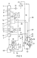
- a gas turbine consisting of a compressor 1, a combustion chamber 2 and a turbine 3 and which drives a generator 4 is connected upstream of a waste heat boiler 7 which has a high-pressure part 7 ′ and a low-pressure part 7 ′′
- the gas turbine 1, 2, 3 is operated at a high inlet temperature of approximately 1200 ° C., which is why the rotor, stator and blading of the turbine 3 are steam-cooled 7 "and emerge from the waste heat boiler 7 at a temperature of approximately 170 ° C.
- the high-pressure part 7 'of the waste heat boiler 7 encloses (in the flow direction of the exhaust gases) a high-pressure superheater 12, a high-pressure evaporator 14, a high-pressure preheater 11 and an intermediate superheater 13.
- a cooling steam superheater 10 is arranged in the low-pressure part 7 "of the waste heat boiler 7, again in the flow direction of the exhaust gases.
- Fresh overheated in high pressure superheater 12 Steam passes through a live steam line 25 provided with a valve 24, via a high-pressure turbine 26, via the reheater 13, into a low-pressure turbine 29 of a steam turbine 27, which drives a generator 28 with an output of approximately 325 MW.
- the steam turbine 27 the steam is expanded, with bleed steam being taken from the low-pressure stage 29 and fed via a bleed line 30 to a feed water tank 23 for heating the same.
- the completely expanded steam from the steam turbine 27 passes via a condenser 31 and a condensate pump 32 into a preheater 33, which is heated by bleed steam from the steam turbine 27 via a removal line 34, via a return line 35 into the feed water tank 23.
- boiler feed water is fed from a feed pump 22 to the low-pressure economizer 8, preheated there and passed into a low-pressure drum 15.
- a part of the drum contents reaches the low-pressure evaporator 9 of the waste heat boiler 7 via the circulation pump 16 and is returned to the drum 15 in the vapor state.
- this steam portion is slightly overheated in the cooling steam superheater 10 arranged on the flue gas side between the high-pressure preheater 11 and the low-pressure evaporator 9 and is fed to the gas turbine for cooling.
- the other part of the drum contents is conveyed into a high-pressure drum 18 by means of a high-pressure pump 17 via the high-pressure economizer 11.
- the working medium enters the high-pressure evaporator 14 and back into the high-pressure drum 18 via a circulation pump 19.
- the high-pressure steam passes from the drum 18 via the high-pressure superheater 12 and the live steam line 25 to the steam turbine 27.
- the slightly overheated cooling steam in the cooling steam superheater reaches the gas turbine 3 via a cooling steam line 20, where it is heated to about 450 ° C. when the parts flushed with hot gas flow through it, so that it comes to about the same temperature as that coming from the reheater 13 in an inlet steam line 38 Has steam, which it is fed to the steam turbine 27 via low-pressure turbine 29.
- a valve 39 can also be installed in the steam line 38 for pressure adjustment.
- the cooling steam Before the cooling steam enters the high-pressure side of the turbine 3 via the cooling steam line 20, part of the cooling steam is conducted via a branch line 21 for cooling the blading and the rotor of the turbine 3, and the other part for cooling the blades and the stator of the turbine 3. After flowing through and cooling the blades, the rotor and the stator, the now superheated steam passes through lines 40, 41 and the common line 36 into the steam line 38, which leads to an intermediate stage of the steam turbine 27. By heating the cooling steam in the 1 turbine 3, the temperature difference between the reheater steam from the reheater 13 and the cooling steam is compensated.
- the guidance of the two cooling steam flows, namely the rotor cooling steam with dash-dotted lines and the guidance of the stator cooling steam with dashed lines and the sealing air guidance with a solid line.
- the sealing air is branched off from a point of appropriate pressure in the compressor 1 and fed to the turbine 3 via a sealing air line 5 (FIG. 1).
- the cooling steam for the rotor blades 42 and the rotor reaches the turbine via the branch line 21 and the cooling steam for the guide blades 43 and the stator via line 20.
- sealing air according to the arrows 6 is fed into air guide channels 44 separated from the steam streams 20, 21 from the turbine inlet side and then discharged into the flow channel.
- the steam cooling the guide vanes 43 and the stator is discharged via the line 41 and the steam cooling the rotor blades 42 and the rotor via the line 40.
- the hollow rotor blades 42 and the heat accumulation segments 46 are fastened in the rotor 49.
- Steam guide channels 45 lead to the hollow blade roots and the heat accumulation segments 46 arranged between the individual blade rows (FIG. 4).
- the air guide channels 44 are arranged separately therefrom.
- Sealing strips 48 are provided between the adjacent base plates 47 of the rotor blades. Due to the slight overpressure prevailing in the air guide channels 44, a small amount of leakage air can flow through air outlet openings 50 into the hot gas channel of the turbine and thereby cause the blocking effect. Sealing elements 51 are provided between the rotor 49 and the steam guide channels 45. The cooling of the guide vanes, not shown, takes place in the same way.
- the above-described steam cooling of the gas turbine according to the invention results in a significantly higher thermal efficiency of the combined system compared to systems only with air cooling of the gas turbine.
- the multi-pressure boiler for cooling the gas turbine can be used to select a pressure which is substantially lower than the live steam pressure of the steam turbine.
- the gas turbine serves as an intermediate superheater and the steam superheated in the intermediate superheater stage 13 can be mixed with the cooling steam flowing through the gas turbine and fed to the low-pressure steam turbine 29.
Landscapes
- Engineering & Computer Science (AREA)
- Chemical & Material Sciences (AREA)
- Combustion & Propulsion (AREA)
- Mechanical Engineering (AREA)
- General Engineering & Computer Science (AREA)
- Engine Equipment That Uses Special Cycles (AREA)
Description
- Die vorliegende Erfindung betrifft ein kombiniertes Gas-Dampfturbinen-Kraftwerk mit dampfgekühlten Gasturbinen-Komponenten, bei welchem die Kühldampferzeugung ausserhalb der Gasturbine in einem Abhitzekessel erfolgt.
- Es sind bereits Anlagen bekanntgeworden, bei welchen zur Kühlung der Gasturbine Dampf verwendet wird, welcher durch Wärmeaustausch mit den Abgasen der Gasturbine erzeugt wird und der Turbinenbeschaufelung so zugeführt wird, dass der Kühldampf im Arbeitsmittelkanal die Turbinenbeschaufelung umströmt und damit den Rotor mit den Schaufelfüssen und das Gehäuse von den Heissgasen abschirmt. Nach dem Durchströmen der Turbine wird der Kühldampfvom Arbeitsgas getrennt aufgefangen und einer Dampfturbine zugeführt (CH-A 364 656).
- Als Nachteil dieser Anordnung muss einmal die ungleichmässige Kühlung des Nabenteiles der Laufschaufeln angesehen werden und zum anderen, dass die saubere Trennung des Arbeitsmittels vom Kühldampf nach dem Durchströmen der Turbine sehr schwierig ist. Die ungleichmässige Kühlung ist insbesondere darauf zurückzuführen, dass der Kühldampf, welcher wesentlich kälter als das Arbeitsmittel ist, in der inneren Kreisringzone des Zuströmkanals zugeführt wird, während das wesentlich heissere Arbeitsmittel an der äusseren Kreisringzone strömt.
- Es ist Aufgabe der vorliegenden Erfindung eine kombinierte Gas-Dampfturbinenanlage zu schaffen, bei welcher die Gasturbine mit einer hohen Eintrittstemperatur betrieben wird und die im Heissgasstrom der Turbine befindlichen Teile dampfgekühlt werden, wobei der Kühldampf in einer Dampfturbine weiter entspannt wird und durch Verwendung einer Zwischenüberhitzung im Dampferzeuger ein hoher Wirkungsgrad der Anlage erzielt werden kann.
- Die vorgenannte Aufgabe wird erfindungsgemäss durch die kennzeichnenden Merkmale des Anspruchs 1 gelöst.
- Der Vorteil der erfindungsgemässen Anordnung ist insbesondere darin zu erblicken, dass durch die Verwendung eines Zweidruck-Abhitzekessels mit Zwischenüberhitzung die Abwärme der Gasturbine besonders gut ausgenützt werden kann und dieser dadurch gewonnene Kühldampf der Gasturbine zugeführt wird, wo er nach der Zwangsführung durch das Gehäuse und die hohlen Leitschaufeln und in einem davon getrennten Strom durch den Rotor und die hohlen Laufschaufeln diese Teile kühlt und dabei diese Gasturbinen-Komponenten gleichzeitig als Überhitzer für einen Teil der Dampfmenge dienen. Dadurch kann dieser die Gasturbine verlassende Dampfstrom dem im Hochdruckteil der Dampfturbine teilentspannten und im Zwischenüberhitzer aufgeheizten Dampf beigemischt werden und in den Niederdruck-Teil der Dampfturbine geleitet werden, ohne dass ein weiteres Aufheizen am Zwischenüberhitzer erforderlich wird. Dies ergibt einen optimalen Ausnützungswert.
- Gemäss dem Anspruch 2 werden mindestens 40% des Gesamtarbeitsmittels für Kühlzwecke der Gasturbine verwendet.
- Da diese Kühldampfmenge nach Aufheizen in der Gasturbine zur Arbeitsleistung im Dampfturbinen-Niederdruck-Teil zur Verfügung steht, tritt praktisch keine Verlustleistung, bzw. Dampfverlust auf.
- Weitere Ausbildungen des Erfindungsgegenstandes gehen aus den Ansprüchen 3 bis 6 hervor.
- Durch die Anordnung, von vom Dampfstrom getrennter Sperrluftkanäle kann vom Verdichter entnommene Luft parallel zum Dampfstrom von der Turbinen-Eintrittsseite zugeführt werden. Da in diesen Sperrluftkanälen vorzugsweise gegenüber dem Heissgaskanal ein leichter Überdruck herrscht, kann eine kleine Luftmenge in diesen überströmen, wodurch ein Sperreffekt erzielt wird. Ein besonderer Vorteil dieser Anordnung ist auch darin zu erblicken, dass aufgrund der relativ geringen Sperrluftmengen zur Sperrung des Heissgases im Rotor und im Schaufelträger, die sonst erforderliche grosse Kühlluftmenge nicht notwendig ist, so dass durch den Wegfall der dafür benötigten zusätzlichen Verdichterleistung eine höhere Gasturbinenleistung als Nutzleistung verfügbar ist.
- Die Anordnung von Dampfführungskanälen im Rotor und Stator, welche mit den Kühldampfführungen in den Schaufeln und den Wärmestausegmenten in Verbindung stehen, ergibt eine gleichmässige Kühlung aller vom heissen Arbeitsmittel umströmten Teile.
- In der Zeichnung ist ein Ausführungsbeispiel einer erfindungsgemässen Kombi-Anlage dargestellt.
- Es zeigt:
- Fig. 1 eine schematische Darstellung einer Kombi-Anlage,
- Fig. 2 ein Schema der Dampf- und Sperrluftführung in der Gasturbine,
- Fig. 3 einen Teilquerschnitt durch einen Rotorabschnitt in der Ebene einer Laufschaufelreihe mit Luft-und Dampfführungskanälen,
- Fig. 4 einen Teil-Querschnitt durch einen Rotorabschnitt mit zwischen zwei Wärmestausegmenten angeordneten Dampfführungskanälen.
- Gemäss Fig. 1 ist in einer erfindungsgemässen kombinierten Gas-Dampfturbinenanlage eine aus einem Verdichter 1, einer Brennkammer 2 und einer Turbine 3 bestehende Gasturbine, welche einen Generator 4 antreibt, einem Abhitzekessel 7 vorgeschaltet, der einen Hochdruckteil 7' und einen Niederdruckteil 7" aufweist. Die Gasturbine 1, 2, 3 wird mit einer hohen Eintrittstemperatur von etwa 1200°C betrieben, weshalb Rotor, Stator und Beschaufelung der Turbine 3 dampfgekühlt werden. Die Turbinenabgase durchströmen im Abhitzekessel 7 die nacheinander in Strömungsrichtung darin angeordneten Hochdruck- 7' und Niederdruckteile 7" und treten mit einer Temperatur von etwa 170°C aus dem Abhitzekessel 7 aus. Der Hochdruckteil 7' des Abhitzekessels 7 umschliesst (in Anströmrichtung der Abgase) einen Hochdrucküberhitzer 12, einen Hochdruckverdampfer 14, einen Hochdruckvorwärmer 11 sowie einen Zwischenüberhitzer 13. Im Niederdruckteil 7" des Abhitzekessels 7 wird - wiederum in Strömungsrichtung der Abgase - angeordnet ein Kühldampfüberhitzer 10, ein Niederdruck- verdampfer 9 und ein Niederdruckvorwärmer 8.
- Der im Hochdrucküberhitzer 12 überhitzte Frischdampf gelangt über eine mit einem Ventil 24 versehene Frischdampfleitung 25 über eine Hochdruckturbine 26 über den Zwischenüberhitzer 13 in eine Niederdruckturbine 29 einer Dampfturbine 27, welche einen Generator 28 mit einer Leistung von etwa 325 MW antreibt. In der Dampfturbine 27 wird der Dampf entspannt, wobei Anzapfdampf der Niederdruckstufe 29 entnommen und über eine Anzapfleitung 30 einem Speisewasserbehälter 23 zur Beheizung desselben zugeführt wird. Der vollständig entspannte Dampf aus der Dampfturbine 27 gelangt über einen Kondensator 31 und eine Kondensatpumpe 32 in einen Vorwärmer 33, der von Anzapfdampf der Dampfturbine 27 über eine Entnahmeleitung 34 beheizt wird, über eine Rückführungsleitung 35 in den Speisewasserbehälter 23.
- Vom Speisewasserbehälter 23 wird Kesselspeisewasser von einer Speisepumpe 22 dem Niederdruckeconomiser 8 zugeführt, dort vorgewärmt und in eine Niederdrucktrommel 15 geleitet. Ein Teil des Trommelinhalts gelangt über die Umwälzpumpe 16 in den Niederdruckverdampfer 9 des Abhitzekessels 7 und wird in dampfförmigem Zustand in die Trommel 15 zurückgeleitet. Dieser Dampfanteil wird erfindungsgemäss im rauchgasseitig zwischen Hochdruckvorwärmer 11 und Niederdruckverdampfer 9 angeordneten Kühldampfüberhitzer 10 leicht überhitzt und der Gasturbine zur Kühlung zugeleitet. Der andere Teil des Trommelinhalts wird mittels einer Hochdruckpumpe 17 über den Hochdruckeconomiser 11 in eine Hochdrucktrommel 18 gefördert. Über eine Umwälzpumpe 19 gelangt das Arbeitsmittel in den Hochdruckverdampfer 14 und zurück in die Hochdrucktrommel 18. Aus der Trommel 18 gelangt der Hochdruckdampf über den Hochdrucküberhitzer 12 und die Frischdampfleitung 25 zur Dampfturbine 27.
- Der im Kühldampfüberhitzer leicht überhitzte Kühldampf gelangt über eine Kühldampfleitung 20 in die Gasturbine 3, wo er beim Durchströmen der vom Heissgas umspülten Teile auf etwa 450°C aufgeheizt wird, so dass er etwa dieselbe Temperatur wie der aus dem Zwischenüberhitzer 13 in einer Zudampfleitung 38 kommende Dampf aufweist, welchem er über Niederdruckturbine 29 der Dampfturbine 27 zugeleitet wird. In die Zudampfleitung 38 kann zur Druckanpassung noch ein Ventil 39 eingebaut sein.
- Vor dem Eintritt des Kühldampfes über die Kühldampfleitung 20 in die Hochdruckseite der Turbine 3 wird ein Teil des Kühldampfes über eine Abzweigleitung 21 zur Kühlung der Beschaufelung und des Rotors der Turbine 3, der andere Teil zur Kühlung der Schaufeln und des Stators der Turbine 3 geführt. Nach dem Durchströmen und Kühlen der Schaufeln, des Rotors und des Stators gelangt der nunmehr stark überhitzte Dampf über Leitungen 40, 41 und die gemeinsame Leitung 36 in die Zudampfleitung 38, welche in eine Zwischenstufe der Dampfturbine 27 führt. Durch das Aufheizen des Kühldampfes in der 1 urbine 3 wird das remperaturgefäiie zwischen dem Zwischenüberhitzerdampf aus dem Zwischenüberhitzer 13 und dem Kühldampf ausgeglichen.
- In der Fig. 2 ist die Führung der beiden Kühldampfströme, nämlich des Rotorkühldampfes mit strichpunktierten und die Führung des Statorkühldampfes mit strichlierten Linien sowie die Sperrluftführung mit einer ausgezogenen Linie bezeichnet. Die Sperrluft wird von einer Stelle entsprechenden Druckes im Verdichter 1 abgezweigt und über eine Sperrluftleitung 5 (Fig. 1) der Turbine 3 zugeführt. Der Kühldampf für die Rotorschaufeln 42 und den Rotor gelangt über die Abzweigleitung 21 und der Kühldampf für die Leitschaufeln 43 und den Stator über die Leitung 20 in die Turbine. Gleichzeitig mit den Dampfströmen 20, 21 wird in bekannterweise Sperrluft gemäss den Pfeilen 6 in von den Dampfströmen 20, 21 getrennte Luftführungskanäle 44 von der Turbineneintrittsseite zugeführt und anschliessend in den Strömungskanal abgeleitet. Nach dem Durchströmen und Kühlen der Turbine 3 wird der die Leitschaufein 43 und den Stator kühlende Dampf über die Leitung 41 und der die Rotorschaufeln 42 und den Rotor kühlende Dampf über die Leitung 40 abgeführt.
- Wie in den Fig. 3 und 4 dargestellt, sind die hohlen Rotorschaufeln 42 und die Wärmestausegmente 46 im Rotor 49 befestigt. Zu den hohlen Schaufelfüssen und den zwischen den einzelnen Schaufelreihen (Fig. 4) angeordneten Wärmestausegmenten 46 führen Dampfführungskanäle 45. Getrennt davon sind die Luftführungskanäle 44 angeordnet. Zwischen den jeweils benachbarten Fussplatten 47 der Rotorschaufeln sind Dichtungsstreifen 48 vorgesehen. Durch den in den Luftführungskanälen 44 herrschenden leichten Überdruck kann eine geringe Leckluftmenge durch Luftaustrittsöffnungen 50 in den Heissgaskanal der Turbine strömen und dadurch den Sperreffekt bewirken. Zwischen dem Rotor 49 und den Dampfführungskanälen 45 sind Dichtelemente 51 vorgesehen. Die Kühlung der nicht gezeigten Leitschaufeln erfolgt auf dieselbe Art.
- Durch die vorstehend beschriebene erfindungsgemässe Dampfkühlung der Gasturbine ergibt sich ein wesentlich höherer thermischer Wirkungsgrad der kombinierten Anlage gegenüber von Anlagen nur mit Luftkühlung der Gasturbine. Ferner kann durch den Mehrdruckkessel zur Kühlung der Gasturbine ein Druck gewählt werden, der wesentlich tiefer liegt, als der Frischdampfdruck der Dampfturbine. Gleichzeitig dient die Gasturbine als Zwischenüberhitzer und der in der Zwischenüberhitzerstufe 13 überhitzte Dampf kann mit dem die Gasturbine durchströmten Kühldampf vermischt und der Niederdruck-Dampfturbine 29 zugeführt werden.
Claims (6)
Applications Claiming Priority (2)
| Application Number | Priority Date | Filing Date | Title |
|---|---|---|---|
| CH2271/81 | 1981-04-03 | ||
| CH227181 | 1981-04-03 |
Publications (2)
| Publication Number | Publication Date |
|---|---|
| EP0062932A1 EP0062932A1 (de) | 1982-10-20 |
| EP0062932B1 true EP0062932B1 (de) | 1984-12-05 |
Family
ID=4229862
Family Applications (1)
| Application Number | Title | Priority Date | Filing Date |
|---|---|---|---|
| EP82200229A Expired EP0062932B1 (de) | 1981-04-03 | 1982-02-25 | Kombiniertes Gas-Dampfturbinen-Kraftwerk |
Country Status (4)
| Country | Link |
|---|---|
| US (1) | US4424668A (de) |
| EP (1) | EP0062932B1 (de) |
| JP (1) | JPS57176309A (de) |
| DE (1) | DE3261410D1 (de) |
Cited By (1)
| Publication number | Priority date | Publication date | Assignee | Title |
|---|---|---|---|---|
| US7143573B2 (en) | 2001-11-02 | 2006-12-05 | Alstom Switzerland Ltd | Gas turbine set |
Families Citing this family (95)
| Publication number | Priority date | Publication date | Assignee | Title |
|---|---|---|---|---|
| JPS5968504A (ja) * | 1982-10-13 | 1984-04-18 | Hitachi Ltd | ガスタ−ビン冷却媒体の熱回収システム |
| US4989405A (en) * | 1983-04-08 | 1991-02-05 | Solar Turbines Incorporated | Combined cycle power plant |
| DE3435382A1 (de) * | 1984-09-27 | 1986-04-03 | Hermann Dipl.-Ing. 5401 Kobern-Gondorf Bongers | Gas-/dampf-verbundturbine mit erhoehtem temperaturniveau |
| US4907405A (en) * | 1989-01-24 | 1990-03-13 | Union Carbide Corporation | Process to cool gas |
| US4991391A (en) * | 1989-01-27 | 1991-02-12 | Westinghouse Electric Corp. | System for cooling in a gas turbine |
| JP3142850B2 (ja) * | 1989-03-13 | 2001-03-07 | 株式会社東芝 | タービンの冷却翼および複合発電プラント |
| DE4029991A1 (de) * | 1990-09-21 | 1992-03-26 | Siemens Ag | Kombinierte gas- und dampfturbinenanlage |
| JPH04298604A (ja) * | 1990-11-20 | 1992-10-22 | General Electric Co <Ge> | 複合サイクル動力装置及び蒸気供給方法 |
| US5233826A (en) * | 1991-04-02 | 1993-08-10 | Cheng Dah Y | Method for starting and operating an advanced regenerative parallel compound dual fluid heat engine-advanced cheng cycle (ACC) |
| DE59205446D1 (de) * | 1991-07-17 | 1996-04-04 | Siemens Ag | Verfahren zum Betreiben einer Gas- und Dampfturbinenanlage und Anlage zur Durchführung des Verfahrens |
| DE59203883D1 (de) * | 1991-07-17 | 1995-11-09 | Siemens Ag | Verfahren zum Betreiben einer Gas- und Dampfturbinenanlage und Anlage zur Durchführung des Verfahrens. |
| US5340274A (en) * | 1991-11-19 | 1994-08-23 | General Electric Company | Integrated steam/air cooling system for gas turbines |
| DE4237665A1 (de) * | 1992-11-07 | 1994-05-11 | Asea Brown Boveri | Verfahren zum Betrieb einer Kombianlage |
| US5320483A (en) * | 1992-12-30 | 1994-06-14 | General Electric Company | Steam and air cooling for stator stage of a turbine |
| JPH06264763A (ja) * | 1993-03-11 | 1994-09-20 | Hitachi Ltd | コンバインドプラントシステム |
| DE4333439C1 (de) * | 1993-09-30 | 1995-02-02 | Siemens Ag | Vorrichtung zur Kühlmittelkühlung einer gekühlten Gasturbine einer Gas- und Dampfturbinenanlage |
| US5577377A (en) * | 1993-11-04 | 1996-11-26 | General Electric Co. | Combined cycle with steam cooled gas turbine |
| US5428950A (en) * | 1993-11-04 | 1995-07-04 | General Electric Co. | Steam cycle for combined cycle with steam cooled gas turbine |
| USRE36497E (en) * | 1993-11-04 | 2000-01-18 | General Electric Co. | Combined cycle with steam cooled gas turbine |
| US5412937A (en) * | 1993-11-04 | 1995-05-09 | General Electric Company | Steam cycle for combined cycle with steam cooled gas turbine |
| USRE36524E (en) * | 1993-11-04 | 2000-01-25 | General Electric Co. | Steam attemperation circuit for a combined cycle steam cooled gas turbine |
| US5628179A (en) * | 1993-11-04 | 1997-05-13 | General Electric Co. | Steam attemperation circuit for a combined cycle steam cooled gas turbine |
| US5491971A (en) * | 1993-12-23 | 1996-02-20 | General Electric Co. | Closed circuit air cooled gas turbine combined cycle |
| DE4344857A1 (de) * | 1993-12-29 | 1995-07-06 | Abb Management Ag | Verfahren und Vorrichtung zum Betreiben einer Gasturbine in einem einfachen und einem mit einer Dampfturbine kombinierten Zyklus |
| JP3353259B2 (ja) * | 1994-01-25 | 2002-12-03 | 謙三 星野 | タ−ビン |
| US5431007A (en) * | 1994-03-04 | 1995-07-11 | Westinghouse Elec Corp | Thermochemically recuperated and steam cooled gas turbine system |
| DE4409567A1 (de) * | 1994-03-21 | 1995-09-28 | Abb Management Ag | Verfahren zur Kühlung von thermisch belasteten Komponenten einer Gasturbogruppe |
| DE4446862C2 (de) * | 1994-12-27 | 1998-01-29 | Siemens Ag | Verfahren zur Kühlung des Kühlmittels einer Gasturbine und Vorrichtung zur Durchführung des Verfahrens |
| US5536143A (en) * | 1995-03-31 | 1996-07-16 | General Electric Co. | Closed circuit steam cooled bucket |
| US5593274A (en) * | 1995-03-31 | 1997-01-14 | General Electric Co. | Closed or open circuit cooling of turbine rotor components |
| KR100470771B1 (ko) * | 1995-03-31 | 2005-06-16 | 제너럴 일렉트릭 캄파니 | 복합사이클식가스터빈의운전방법 |
| US5839267A (en) * | 1995-03-31 | 1998-11-24 | General Electric Co. | Cycle for steam cooled gas turbines |
| DE19512466C1 (de) * | 1995-04-03 | 1996-08-22 | Siemens Ag | Verfahren zum Betreiben eines Abhitzedampferzeugers sowie danach arbeitender Abhitzedampferzeuger |
| WO1997007323A1 (de) * | 1995-08-18 | 1997-02-27 | Siemens Aktiengesellschaft | Gas- und dampfturbinenanlage und verfahren zum betreiben einer derartigen anlage sowie abhitzedampferzeuger für eine gas- und dampfturbinenanlage |
| US6105362A (en) * | 1995-09-22 | 2000-08-22 | Kabushiki Kaisha Toshiba | Combined cycle power plant with gas turbine cooling system |
| EP1184541B1 (de) * | 1995-09-22 | 2004-12-08 | Kabushiki Kaisha Toshiba | Kraftanlage mit kombiniertem Kreislauf |
| DE19536839A1 (de) * | 1995-10-02 | 1997-04-30 | Abb Management Ag | Verfahren zum Betrieb einer Kraftwerksanlage |
| US5649416A (en) * | 1995-10-10 | 1997-07-22 | General Electric Company | Combined cycle power plant |
| DE19547803C1 (de) * | 1995-12-20 | 1997-04-10 | Siemens Ag | Dampfturbinenanlage |
| DE19609912A1 (de) * | 1996-03-14 | 1997-09-18 | Asea Brown Boveri | Verfahren zum Betrieb einer Kraftwerksanlage |
| US6164056A (en) * | 1996-07-24 | 2000-12-26 | Mitsubishi Heavy Industries, Ltd. | Combined cycle electric power plant |
| JPH1061457A (ja) * | 1996-08-27 | 1998-03-03 | Mitsubishi Heavy Ind Ltd | 複合サイクル発電プラント用ガスタービン |
| US5953900A (en) * | 1996-09-19 | 1999-09-21 | Siemens Westinghouse Power Corporation | Closed loop steam cooled steam turbine |
| JP3621523B2 (ja) * | 1996-09-25 | 2005-02-16 | 株式会社東芝 | ガスタービンの動翼冷却装置 |
| US5775091A (en) * | 1996-10-21 | 1998-07-07 | Westinghouse Electric Corporation | Hydrogen fueled power plant |
| JP3564242B2 (ja) * | 1996-10-29 | 2004-09-08 | 三菱重工業株式会社 | 蒸気冷却ガスタービンの冷却蒸気系統システム |
| JP3564241B2 (ja) * | 1996-10-29 | 2004-09-08 | 三菱重工業株式会社 | コンバインドサイクル発電プラント |
| JPH10131719A (ja) * | 1996-10-29 | 1998-05-19 | Mitsubishi Heavy Ind Ltd | 蒸気冷却ガスタービンシステム |
| JP3500020B2 (ja) * | 1996-11-29 | 2004-02-23 | 三菱重工業株式会社 | 蒸気冷却ガスタービンシステム |
| US5873238A (en) * | 1996-12-23 | 1999-02-23 | Siemens Westinghouse Power Corporation | Startup cooling steam generator for combustion turbine |
| DE19702830C1 (de) * | 1997-01-27 | 1998-05-14 | Siemens Ag | Kombinierte Gas- und Dampfturbinenanlage sowie Verfahren zu deren Betrieb |
| WO1998055736A1 (fr) | 1997-06-04 | 1998-12-10 | Mitsubishi Heavy Industries, Ltd. | Structure d'etancheite montee entre les disques d'une turbine a gaz |
| US6286297B1 (en) * | 1997-07-02 | 2001-09-11 | Mitsubishi Heavy Industries, Ltd. | Steam cooled type combined cycle power generation plant and operation method thereof |
| JP3530345B2 (ja) | 1997-07-04 | 2004-05-24 | 三菱重工業株式会社 | コンバインドサイクル発電プラント |
| EP1041261A4 (de) * | 1997-12-15 | 2003-07-16 | Hitachi Ltd | Gasturbine zur energieerzeugung sowie integriertes energieerzeugungssystem |
| DE69835593T2 (de) * | 1998-01-23 | 2007-09-13 | Mitsubishi Heavy Industries, Ltd. | Kraftanlage mit kombiniertem kreislauf |
| DE19882242B4 (de) * | 1998-01-23 | 2010-12-23 | Mitsubishi Heavy Industries, Ltd. | Gas- und Dampfturbinen-Kraftwerk |
| JP4126108B2 (ja) * | 1998-02-25 | 2008-07-30 | 三菱重工業株式会社 | ガスタービンコンバインドプラント、その運転方法、及びガスタービン高温部蒸気冷却システム |
| US6125623A (en) * | 1998-03-03 | 2000-10-03 | Siemens Westinghouse Power Corporation | Heat exchanger for operating with a combustion turbine in either a simple cycle or a combined cycle |
| KR20000071290A (ko) | 1999-01-29 | 2000-11-25 | 제이 엘. 차스킨, 버나드 스나이더, 아더엠. 킹 | 조합된 사이클 시스템 및 가스 터빈 |
| DE10041413B4 (de) * | 1999-08-25 | 2011-05-05 | Alstom (Switzerland) Ltd. | Verfahren zum Betrieb einer Kraftwerksanlage |
| DE19943782C5 (de) * | 1999-09-13 | 2015-12-17 | Siemens Aktiengesellschaft | Gas- und Dampfturbinenanlage |
| US6397575B2 (en) * | 2000-03-23 | 2002-06-04 | General Electric Company | Apparatus and methods of reheating gas turbine cooling steam and high pressure steam turbine exhaust in a combined cycle power generating system |
| US6574966B2 (en) | 2000-06-08 | 2003-06-10 | Hitachi, Ltd. | Gas turbine for power generation |
| US6640550B2 (en) | 2001-11-02 | 2003-11-04 | Alstom (Switzerland) Ltd | Gas turbo-group with cooling air system |
| DE60324368D1 (de) * | 2002-08-09 | 2008-12-11 | Hitachi Ltd | Kombikraftwerk |
| AU2003288262A1 (en) * | 2002-12-09 | 2004-06-30 | Siemens Aktiengesellschaft | Method for operation of a gas and steam power station and gas and steam power station for carrying out said method |
| WO2004069381A1 (en) * | 2003-01-28 | 2004-08-19 | Fluor Corporation | Configuration and process for carbonyl removal |
| RU2241132C1 (ru) * | 2003-08-06 | 2004-11-27 | Общество с ограниченной ответственностью "Авиагаз-инжиниринг" | Комбинированная газотурбинная установка |
| RU2258147C1 (ru) * | 2003-12-29 | 2005-08-10 | Открытое Акционерное Общество "Всероссийский теплотехнический научно-исследовательский институт (ВТИ)" | Способ замещения газотурбинного топлива в энергетических циклах |
| RU2284416C2 (ru) * | 2004-12-09 | 2006-09-27 | Владимир Леонидович Письменный | Утилизатор тепловой энергии |
| RU2288363C2 (ru) * | 2005-01-11 | 2006-11-27 | Игорь Алексеевич Иванов | Способ работы парогазовой установки и устройство для его осуществления |
| EP1998013A3 (de) * | 2007-04-16 | 2009-05-06 | Turboden S.r.l. | Vorrichtung zur Erzeugung von elektrischer Energie unter Verwendung von Hochtemperaturgasen |
| DE102008062588B4 (de) * | 2008-12-16 | 2010-11-25 | Siemens Aktiengesellschaft | Verfahren zur Stabilisierung der Netzfrequenz eines elektrischen Stromnetzes |
| US20100263605A1 (en) * | 2009-04-17 | 2010-10-21 | Ajit Singh Sengar | Method and system for operating a steam generation facility |
| IT1395820B1 (it) * | 2009-09-25 | 2012-10-26 | Nuovo Pignone Spa | Sistema di raffreddamento per una turbina a gas e relativo metodo di funzionamento |
| JP4880019B2 (ja) * | 2009-10-14 | 2012-02-22 | 川崎重工業株式会社 | タービンのシール構造 |
| US20110232298A1 (en) * | 2010-03-23 | 2011-09-29 | General Electric Company | System and method for cooling gas turbine components |
| RU2467187C2 (ru) * | 2010-11-03 | 2012-11-20 | ООО "Центр КОРТЭС" | Способ работы газотурбинной установки |
| RU2466285C2 (ru) * | 2010-11-09 | 2012-11-10 | Федеральное государственное унитарное предприятие "Центральный институт авиационного моторостроения имени П.И. Баранова" | Парогенерирующая установка |
| CN102678332B (zh) * | 2011-03-15 | 2016-02-17 | 杜臣 | 再热涡旋复合式热机 |
| CN102797565B (zh) * | 2011-05-26 | 2016-02-17 | 杜臣 | 涡旋复合式热机 |
| CN102278155A (zh) * | 2011-06-02 | 2011-12-14 | 马鞍山科达洁能股份有限公司 | 燃气和蒸汽轮机系统 |
| US9334753B2 (en) * | 2011-10-12 | 2016-05-10 | General Electric Company | Control system and methods for controlling the operation of power generation systems |
| US8997498B2 (en) | 2011-10-12 | 2015-04-07 | General Electric Company | System for use in controlling the operation of power generation systems |
| WO2013144111A1 (de) | 2012-03-30 | 2013-10-03 | Alstom Technology Ltd | Gasturbine mit regelbarem kühlluftsystem |
| US10309642B2 (en) | 2012-08-03 | 2019-06-04 | Shell Oil Company | Process for recovering power in a process for producing ethylene |
| RU2520762C1 (ru) * | 2012-12-17 | 2014-06-27 | Владимир Леонидович Письменный | Парогазовая установка |
| RU2523087C1 (ru) * | 2013-03-22 | 2014-07-20 | Владимир Леонидович Письменный | Парогазотурбинная установка |
| RU2545115C2 (ru) * | 2013-04-23 | 2015-03-27 | Федеральное государственное бюджетное образовательное учреждение высшего профессионального образования Казанский национальный исследовательский технический университет им. А.Н. Туполева-КАИ" (КНИТУ-КАИ) | Энергетическая установка |
| US20170201158A1 (en) * | 2014-05-30 | 2017-07-13 | Leartek Pty Ltd | Exhaust heat recovery system control method and device |
| RU2620610C1 (ru) * | 2016-02-15 | 2017-05-29 | федеральное государственное бюджетное образовательное учреждение высшего образования "Самарский государственный технический университет" | Способ работы парогазовой установки электростанции |
| EP3546709A1 (de) * | 2018-03-29 | 2019-10-02 | Volvo Car Corporation | Fahrzeug mit system zur rückgewinnung von abwärme |
| DE102018118275A1 (de) * | 2018-07-27 | 2020-01-30 | Valeo Siemens Eautomotive Germany Gmbh | Rotoranordnung für eine elektrische Maschine, elektrische Maschine für ein Fahrzeug und Fahrzeug |
| RU2693567C1 (ru) * | 2018-07-31 | 2019-07-03 | федеральное государственное бюджетное образовательное учреждение высшего образования "Самарский государственный технический университет" | Способ работы парогазовой установки электростанции |
Family Cites Families (8)
| Publication number | Priority date | Publication date | Assignee | Title |
|---|---|---|---|---|
| US1901873A (en) | 1926-08-17 | 1933-03-21 | Holzwarth Gas Turbine Co | Multistage constant volume explosion process and apparatus |
| US2403388A (en) | 1944-04-26 | 1946-07-02 | Gen Electric | Gas turbine power plant |
| CH286635A (de) * | 1948-08-24 | 1952-10-31 | Kluge Friedrich Ing Dr | Verfahren zum Betrieb einer Kraftanlage. |
| NL75236C (de) * | 1950-03-13 | |||
| FR1318433A (fr) * | 1961-03-30 | 1963-02-15 | Bbc Brown Boveri & Cie | Installation combinée d'une turbine à gaz et d'un groupe moteur à vapeur |
| US3150487A (en) * | 1963-04-08 | 1964-09-29 | Gen Electric | Steam turbine-gas turbine power plant |
| US4314442A (en) | 1978-10-26 | 1982-02-09 | Rice Ivan G | Steam-cooled blading with steam thermal barrier for reheat gas turbine combined with steam turbine |
| US4333309A (en) | 1980-01-30 | 1982-06-08 | Coronel Paul D | Steam assisted gas turbine engine |
-
1982
- 1982-02-25 DE DE8282200229T patent/DE3261410D1/de not_active Expired
- 1982-02-25 EP EP82200229A patent/EP0062932B1/de not_active Expired
- 1982-03-10 US US06/356,728 patent/US4424668A/en not_active Expired - Lifetime
- 1982-04-01 JP JP57052363A patent/JPS57176309A/ja active Granted
Cited By (1)
| Publication number | Priority date | Publication date | Assignee | Title |
|---|---|---|---|---|
| US7143573B2 (en) | 2001-11-02 | 2006-12-05 | Alstom Switzerland Ltd | Gas turbine set |
Also Published As
| Publication number | Publication date |
|---|---|
| EP0062932A1 (de) | 1982-10-20 |
| DE3261410D1 (en) | 1985-01-17 |
| JPS6340244B2 (de) | 1988-08-10 |
| US4424668A (en) | 1984-01-10 |
| JPS57176309A (en) | 1982-10-29 |
Similar Documents
| Publication | Publication Date | Title |
|---|---|---|
| EP0062932B1 (de) | Kombiniertes Gas-Dampfturbinen-Kraftwerk | |
| DE69504240T2 (de) | Dampfkühlung mit Reservekühlung durch Luft für eine Gasturbine | |
| EP0906494B1 (de) | Turbinenwelle sowie verfahren zur kühlung einer turbinenwelle | |
| DE69809532T2 (de) | Dampfgekühlte Gasturbinenanlage | |
| EP1386070B1 (de) | Verfahren zur kühlung einer gasturbine und gasturbinenanlage | |
| DE19645322B4 (de) | Kombinierte Kraftwerksanlage mit einem Zwangsdurchlaufdampferzeuger als Gasturbinen-Kühlluftkühler | |
| DE2913548C2 (de) | Wellenkühlung für ein Gasturbinentriebwerk | |
| DE60034423T2 (de) | Vorrichtung und Verfahren zum Wiedererhitzen von Gasturbinenkühldampf und Hochdruckdampfturbinenabdampf in einem Gas- und Dampfturbinen-Energieerzeugungssystem | |
| EP2368021B1 (de) | Abhitzedampferzeuger sowie ein verfahren zum verbesserten betrieb eines abhitzedampferzeugers | |
| DE60126721T2 (de) | Kombiniertes Kreislaufsystem mit Gasturbine | |
| EP0523467B1 (de) | Verfahren zum Betreiben einer Gas- und Dampfturbinenanlage und Anlage zur Durchführung des Verfahrens | |
| DE60033357T2 (de) | Kombikraftwerk mit Gasturbine | |
| DE112017001695B4 (de) | Anlage und Betriebsverfahren dafür | |
| EP0929736B1 (de) | Dampfturbine sowie verfahren zur kühlung einer dampfturbine im ventilationsbetrieb | |
| DE102018123663A1 (de) | Brennstoffvorwärmsystem für eine Verbrennungsgasturbine | |
| EP1119688A1 (de) | Gas- und dampfturbinenanlage | |
| EP0666412B1 (de) | Verfahren zur Kühlung von Kühlluft für eine Gasturbine | |
| DE19837251C1 (de) | Gas- und Dampfturbinenanlage | |
| WO2000004285A2 (de) | Gas- und dampfturbinenanlage | |
| EP0981681B1 (de) | Gas- und dampfturbinenanlage und verfahren zur kühlung des kühlmittels der gasturbine einer derartigen anlage | |
| WO2000004279A2 (de) | Gas- und dampfturbinenanlage | |
| EP0158629B1 (de) | Dampfkreislauf für Dampfkraftanlagen | |
| WO1999057421A1 (de) | Gas- und dampfturbinenanlage | |
| EP0868599B1 (de) | Verfahren zum betreiben einer gasturbine und danach arbeitende gasturbine | |
| DE112016006048T5 (de) | Dampfturbine |
Legal Events
| Date | Code | Title | Description |
|---|---|---|---|
| PUAI | Public reference made under article 153(3) epc to a published international application that has entered the european phase |
Free format text: ORIGINAL CODE: 0009012 |
|
| AK | Designated contracting states |
Designated state(s): CH DE FR GB |
|
| 17P | Request for examination filed |
Effective date: 19830224 |
|
| GRAA | (expected) grant |
Free format text: ORIGINAL CODE: 0009210 |
|
| AK | Designated contracting states |
Designated state(s): CH DE FR GB LI |
|
| PG25 | Lapsed in a contracting state [announced via postgrant information from national office to epo] |
Ref country code: FR Free format text: THE PATENT HAS BEEN ANNULLED BY A DECISION OF A NATIONAL AUTHORITY Effective date: 19841205 |
|
| REF | Corresponds to: |
Ref document number: 3261410 Country of ref document: DE Date of ref document: 19850117 |
|
| EN | Fr: translation not filed | ||
| PLBE | No opposition filed within time limit |
Free format text: ORIGINAL CODE: 0009261 |
|
| STAA | Information on the status of an ep patent application or granted ep patent |
Free format text: STATUS: NO OPPOSITION FILED WITHIN TIME LIMIT |
|
| 26N | No opposition filed | ||
| PGFP | Annual fee paid to national office [announced via postgrant information from national office to epo] |
Ref country code: CH Payment date: 19910524 Year of fee payment: 10 |
|
| PG25 | Lapsed in a contracting state [announced via postgrant information from national office to epo] |
Ref country code: LI Effective date: 19920229 Ref country code: CH Effective date: 19920229 |
|
| REG | Reference to a national code |
Ref country code: CH Ref legal event code: PL |
|
| PGFP | Annual fee paid to national office [announced via postgrant information from national office to epo] |
Ref country code: GB Payment date: 20010112 Year of fee payment: 20 |
|
| PGFP | Annual fee paid to national office [announced via postgrant information from national office to epo] |
Ref country code: DE Payment date: 20010205 Year of fee payment: 20 |
|
| PG25 | Lapsed in a contracting state [announced via postgrant information from national office to epo] |
Ref country code: DE Free format text: LAPSE BECAUSE OF THE APPLICANT RENOUNCES Effective date: 20011012 |
|
| REG | Reference to a national code |
Ref country code: GB Ref legal event code: IF02 |
|
| PG25 | Lapsed in a contracting state [announced via postgrant information from national office to epo] |
Ref country code: GB Free format text: LAPSE BECAUSE OF EXPIRATION OF PROTECTION Effective date: 20020224 |
|
| REG | Reference to a national code |
Ref country code: GB Ref legal event code: PE20 Effective date: 20020224 |