EP0062956A1 - Dispositif de support - Google Patents
Dispositif de support Download PDFInfo
- Publication number
- EP0062956A1 EP0062956A1 EP82200432A EP82200432A EP0062956A1 EP 0062956 A1 EP0062956 A1 EP 0062956A1 EP 82200432 A EP82200432 A EP 82200432A EP 82200432 A EP82200432 A EP 82200432A EP 0062956 A1 EP0062956 A1 EP 0062956A1
- Authority
- EP
- European Patent Office
- Prior art keywords
- parts
- supporting member
- spring
- another
- fixed
- Prior art date
- Legal status (The legal status is an assumption and is not a legal conclusion. Google has not performed a legal analysis and makes no representation as to the accuracy of the status listed.)
- Granted
Links
Images
Classifications
-
- F—MECHANICAL ENGINEERING; LIGHTING; HEATING; WEAPONS; BLASTING
- F21—LIGHTING
- F21V—FUNCTIONAL FEATURES OR DETAILS OF LIGHTING DEVICES OR SYSTEMS THEREOF; STRUCTURAL COMBINATIONS OF LIGHTING DEVICES WITH OTHER ARTICLES, NOT OTHERWISE PROVIDED FOR
- F21V21/00—Supporting, suspending, or attaching arrangements for lighting devices; Hand grips
- F21V21/14—Adjustable mountings
- F21V21/32—Flexible tubes
-
- F—MECHANICAL ENGINEERING; LIGHTING; HEATING; WEAPONS; BLASTING
- F16—ENGINEERING ELEMENTS AND UNITS; GENERAL MEASURES FOR PRODUCING AND MAINTAINING EFFECTIVE FUNCTIONING OF MACHINES OR INSTALLATIONS; THERMAL INSULATION IN GENERAL
- F16M—FRAMES, CASINGS OR BEDS OF ENGINES, MACHINES OR APPARATUS, NOT SPECIFIC TO ENGINES, MACHINES OR APPARATUS PROVIDED FOR ELSEWHERE; STANDS; SUPPORTS
- F16M11/00—Stands or trestles as supports for apparatus or articles placed thereon ; Stands for scientific apparatus such as gravitational force meters
- F16M11/02—Heads
- F16M11/04—Means for attachment of apparatus; Means allowing adjustment of the apparatus relatively to the stand
- F16M11/06—Means for attachment of apparatus; Means allowing adjustment of the apparatus relatively to the stand allowing pivoting
- F16M11/10—Means for attachment of apparatus; Means allowing adjustment of the apparatus relatively to the stand allowing pivoting around a horizontal axis
-
- F—MECHANICAL ENGINEERING; LIGHTING; HEATING; WEAPONS; BLASTING
- F16—ENGINEERING ELEMENTS AND UNITS; GENERAL MEASURES FOR PRODUCING AND MAINTAINING EFFECTIVE FUNCTIONING OF MACHINES OR INSTALLATIONS; THERMAL INSULATION IN GENERAL
- F16M—FRAMES, CASINGS OR BEDS OF ENGINES, MACHINES OR APPARATUS, NOT SPECIFIC TO ENGINES, MACHINES OR APPARATUS PROVIDED FOR ELSEWHERE; STANDS; SUPPORTS
- F16M11/00—Stands or trestles as supports for apparatus or articles placed thereon ; Stands for scientific apparatus such as gravitational force meters
- F16M11/20—Undercarriages with or without wheels
- F16M11/2007—Undercarriages with or without wheels comprising means allowing pivoting adjustment
- F16M11/2014—Undercarriages with or without wheels comprising means allowing pivoting adjustment around a vertical axis
Definitions
- the invention relates to a supporting device comprising at least two relatively rotatable parts.
- the invention has for its object to provide a supporting device of the kind set forth, in which the two parts can be readily turned with respect to one another and can maintain a fixed position relative to one another without the use of locking members.
- this can be achieved by arranging in the two parts a biassed, helically wound tensile spring fixed at least at two points.
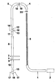
- the supporting construction comprises a tubular part 1 having a straight portion and a quarter bend.
- a member to be supported for example, a lamp holder 2.
- the supporting device furthermore comprises a tubular part 4 formed by a quarter bend and a tubular part 5 having a straight portion and an adjoined quarter bend.
- the supporting device is furthermore provided with a straight, tubular part 6, to the lower end of which is secured a supporting plate 7.
- a tubing 8 associated with the supporting member and to the lower end of the tubing 8 is fastened a supporting plate 9.
- Beneath the supporting plate 9 is fastened a tubing 10 so that-the centre line of this tubing 10 coincides with the centre line of the tubing 8.
- the lower end of the tubing 5 can be coupled with the tubing 6 with the aid of a tie piece 11 formed by a tubing 12 provided between its ends with a thickened, annular portion 13.
- This annular portion 13 has two tapped holes for receiving guard screws 14.
- a coupling piece 15 which is provided at its lower end with a thickened, annular portion 16 also having two tapped holes for receiving guard screws 17.
- a coupling piece 18 having nears its middle a thickened, annular portion 19 so that the ends of said coupling piece can be inserted into the ends of the tubings 5 and 4, the annular portion thus being locked between the ends of the tubings 4 and 5.
- a similar coupling piece 20 is used for the disposition on the ends of the tubings 1 and 4 to be joined to one another.
- the coupling piece 20 When uounting the supporting member described above first the coupling piece 20 is slipped onto the spring, then the tubing 4, the coupling 5piece 18, the tubing 5 and the coupling piece 11 in a manner such that the various parts of the supporting member, through which the spring 3 is slid, are rigidly joined to one another. Subsequently the sping 3 is firmly stretched and then fixed in the coupling piece 11 with the aid of the guard screws 14. It will be obvious that the various parts 1, 20, 4, 18, 5 and 11 are firmly drawn to one another by the spring.
- the remaining part of the spring is passed through the parts 6, 8 and 10 of the supporting member, said remaining part of the spring being also biassed and finally fixed to the coupling piece 15 with the aid of the guard screws 17.
- the supporting plate 9 tends to move towards the supporting plate 7 by the action of the spring tension produced in the portion of the tensile spring located between the guard screws 14 and the guard screws 17.
- the arrangement may be such that during mounting and generating the tensile force in the last-mentioned portion of the tensile spring 3 the plates 7 and 9 come into contact with one another, whereas an alternative resides in that with the aid of stop members (not shown) it can be ensured that the supporting plates 7 and 9 are spaced apart by a minimum distance.
- a plurality of registering springs may, as an alternative,be employed.
Landscapes
- Engineering & Computer Science (AREA)
- General Engineering & Computer Science (AREA)
- Mechanical Engineering (AREA)
- Springs (AREA)
- Mutual Connection Of Rods And Tubes (AREA)
- Devices For Conveying Motion By Means Of Endless Flexible Members (AREA)
- Mechanical Operated Clutches (AREA)
- Clamps And Clips (AREA)
- Electrical Discharge Machining, Electrochemical Machining, And Combined Machining (AREA)
- Fluid-Damping Devices (AREA)
Priority Applications (1)
| Application Number | Priority Date | Filing Date | Title |
|---|---|---|---|
| AT82200432T ATE14342T1 (de) | 1981-04-11 | 1982-04-08 | Tragvorrichtung. |
Applications Claiming Priority (2)
| Application Number | Priority Date | Filing Date | Title |
|---|---|---|---|
| NL8101790 | 1981-04-11 | ||
| NL8101790A NL8101790A (nl) | 1981-04-11 | 1981-04-11 | Ondersteuningsinrichting. |
Publications (2)
| Publication Number | Publication Date |
|---|---|
| EP0062956A1 true EP0062956A1 (fr) | 1982-10-20 |
| EP0062956B1 EP0062956B1 (fr) | 1985-07-17 |
Family
ID=19837337
Family Applications (1)
| Application Number | Title | Priority Date | Filing Date |
|---|---|---|---|
| EP82200432A Expired EP0062956B1 (fr) | 1981-04-11 | 1982-04-08 | Dispositif de support |
Country Status (4)
| Country | Link |
|---|---|
| EP (1) | EP0062956B1 (fr) |
| AT (1) | ATE14342T1 (fr) |
| DE (1) | DE3264748D1 (fr) |
| NL (1) | NL8101790A (fr) |
Citations (8)
| Publication number | Priority date | Publication date | Assignee | Title |
|---|---|---|---|---|
| BE483690A (fr) * | ||||
| US2557507A (en) * | 1950-05-11 | 1951-06-19 | Jr Victor Lang | Adjustable joint structure for electric lamp supports |
| FR1105984A (fr) * | 1954-06-08 | 1955-12-09 | Support de lampe perfectionné | |
| US3266059A (en) * | 1963-06-19 | 1966-08-16 | North American Aviation Inc | Prestressed flexible joint for mechanical arms and the like |
| DE1909716A1 (de) * | 1968-02-26 | 1969-09-25 | Oram John Anderson | Biegsamer Staender |
| FR2184263A5 (fr) * | 1972-05-12 | 1973-12-21 | Test Sa | |
| FR2363021A1 (fr) * | 1976-08-27 | 1978-03-24 | Oesterr Klima Technik | Bras a articulations multiples |
| DE2840314A1 (de) * | 1978-09-15 | 1980-03-27 | Robert Goedecke | Vorrichtung zur gelenkigen verbindung zweier geraeteteile |
-
1981
- 1981-04-11 NL NL8101790A patent/NL8101790A/nl not_active Application Discontinuation
-
1982
- 1982-04-08 AT AT82200432T patent/ATE14342T1/de not_active IP Right Cessation
- 1982-04-08 EP EP82200432A patent/EP0062956B1/fr not_active Expired
- 1982-04-08 DE DE8282200432T patent/DE3264748D1/de not_active Expired
Patent Citations (8)
| Publication number | Priority date | Publication date | Assignee | Title |
|---|---|---|---|---|
| BE483690A (fr) * | ||||
| US2557507A (en) * | 1950-05-11 | 1951-06-19 | Jr Victor Lang | Adjustable joint structure for electric lamp supports |
| FR1105984A (fr) * | 1954-06-08 | 1955-12-09 | Support de lampe perfectionné | |
| US3266059A (en) * | 1963-06-19 | 1966-08-16 | North American Aviation Inc | Prestressed flexible joint for mechanical arms and the like |
| DE1909716A1 (de) * | 1968-02-26 | 1969-09-25 | Oram John Anderson | Biegsamer Staender |
| FR2184263A5 (fr) * | 1972-05-12 | 1973-12-21 | Test Sa | |
| FR2363021A1 (fr) * | 1976-08-27 | 1978-03-24 | Oesterr Klima Technik | Bras a articulations multiples |
| DE2840314A1 (de) * | 1978-09-15 | 1980-03-27 | Robert Goedecke | Vorrichtung zur gelenkigen verbindung zweier geraeteteile |
Also Published As
| Publication number | Publication date |
|---|---|
| DE3264748D1 (en) | 1985-08-22 |
| EP0062956B1 (fr) | 1985-07-17 |
| NL8101790A (nl) | 1982-11-01 |
| ATE14342T1 (de) | 1985-08-15 |
Similar Documents
| Publication | Publication Date | Title |
|---|---|---|
| SU1153849A3 (ru) | Устройство дл креплени электрических кабелей или трубопроводов | |
| US4878662A (en) | Exercise machine weight guide | |
| KR100453924B1 (ko) | 시트 서스펜션장치 및 그 조정기구 | |
| RU2076188C1 (ru) | Соединительный штифт | |
| IT1256939B (it) | Fascetta per tubo flessibile. | |
| US4002953A (en) | Device for fixing a printed circuit board to a casket-like support | |
| GB2193902A (en) | Climbing aids | |
| US4452414A (en) | Supporting device | |
| US4274612A (en) | Multiple diameter wire bundle support | |
| KR930010355A (ko) | 차량용 배기라인부재의 관절연결장치 | |
| EP0062956A1 (fr) | Dispositif de support | |
| DE68912761D1 (de) | Endanschlussblock mit Kabelklemmenvorrichtung, insbesondere für Haushaltsgeräte. | |
| US5857965A (en) | Operating stage | |
| US4679234A (en) | Telephone cord twist restrainer | |
| CN214870195U (zh) | 吊杆安装座 | |
| US4244238A (en) | Remote control wire apparatus | |
| ES2026859T3 (es) | Abrazadera de manguera. | |
| US3998519A (en) | Lamp support | |
| EP0102973A1 (fr) | Dispositif de formage de noyau | |
| DE59000028D1 (de) | Rohrverbindung zwischen zwei stumpf miteinander zu verbindenden rohrenden. | |
| FR2704362B1 (fr) | Connecteur électrique à fixation magnétique sur un rail à deux conducteurs. | |
| SU1093846A1 (ru) | Зубчатое колесо измен емого диаметра | |
| US2170217A (en) | Electrical connecting device | |
| SU1198632A1 (ru) | Устройство для укладки, хранения и сматывания гибкого кабеля | |
| KR100212778B1 (ko) | 로드 고정용 크립 |
Legal Events
| Date | Code | Title | Description |
|---|---|---|---|
| PUAI | Public reference made under article 153(3) epc to a published international application that has entered the european phase |
Free format text: ORIGINAL CODE: 0009012 |
|
| AK | Designated contracting states |
Designated state(s): AT BE CH DE FR GB IT LU NL SE |
|
| 17P | Request for examination filed |
Effective date: 19830418 |
|
| ITF | It: translation for a ep patent filed | ||
| GRAA | (expected) grant |
Free format text: ORIGINAL CODE: 0009210 |
|
| AK | Designated contracting states |
Designated state(s): AT BE CH DE FR GB IT LI LU NL SE |
|
| PG25 | Lapsed in a contracting state [announced via postgrant information from national office to epo] |
Ref country code: LI Effective date: 19850717 Ref country code: CH Effective date: 19850717 Ref country code: AT Effective date: 19850717 |
|
| REF | Corresponds to: |
Ref document number: 14342 Country of ref document: AT Date of ref document: 19850815 Kind code of ref document: T |
|
| PG25 | Lapsed in a contracting state [announced via postgrant information from national office to epo] |
Ref country code: SE Effective date: 19850730 |
|
| REF | Corresponds to: |
Ref document number: 3264748 Country of ref document: DE Date of ref document: 19850822 |
|
| ET | Fr: translation filed | ||
| REG | Reference to a national code |
Ref country code: CH Ref legal event code: PL |
|
| PG25 | Lapsed in a contracting state [announced via postgrant information from national office to epo] |
Ref country code: LU Free format text: LAPSE BECAUSE OF NON-PAYMENT OF DUE FEES Effective date: 19860430 |
|
| PLBE | No opposition filed within time limit |
Free format text: ORIGINAL CODE: 0009261 |
|
| STAA | Information on the status of an ep patent application or granted ep patent |
Free format text: STATUS: NO OPPOSITION FILED WITHIN TIME LIMIT |
|
| 26N | No opposition filed | ||
| PGFP | Annual fee paid to national office [announced via postgrant information from national office to epo] |
Ref country code: FR Payment date: 19890428 Year of fee payment: 8 |
|
| ITTA | It: last paid annual fee | ||
| PGFP | Annual fee paid to national office [announced via postgrant information from national office to epo] |
Ref country code: NL Payment date: 19890430 Year of fee payment: 8 Ref country code: GB Payment date: 19890430 Year of fee payment: 8 |
|
| PGFP | Annual fee paid to national office [announced via postgrant information from national office to epo] |
Ref country code: BE Payment date: 19890512 Year of fee payment: 8 |
|
| PGFP | Annual fee paid to national office [announced via postgrant information from national office to epo] |
Ref country code: DE Payment date: 19890616 Year of fee payment: 8 |
|
| PG25 | Lapsed in a contracting state [announced via postgrant information from national office to epo] |
Ref country code: GB Effective date: 19900408 |
|
| PG25 | Lapsed in a contracting state [announced via postgrant information from national office to epo] |
Ref country code: BE Effective date: 19900430 |
|
| BERE | Be: lapsed |
Owner name: ANSEMS HENRICUS JOSEPHUS Effective date: 19900430 |
|
| PG25 | Lapsed in a contracting state [announced via postgrant information from national office to epo] |
Ref country code: NL Effective date: 19901101 |
|
| GBPC | Gb: european patent ceased through non-payment of renewal fee | ||
| NLV4 | Nl: lapsed or anulled due to non-payment of the annual fee | ||
| PG25 | Lapsed in a contracting state [announced via postgrant information from national office to epo] |
Ref country code: FR Effective date: 19901228 |
|
| PG25 | Lapsed in a contracting state [announced via postgrant information from national office to epo] |
Ref country code: DE Effective date: 19910101 |
|
| REG | Reference to a national code |
Ref country code: FR Ref legal event code: ST |