EP0063039A2 - Machines à fabriquer des tuiles - Google Patents
Machines à fabriquer des tuiles Download PDFInfo
- Publication number
- EP0063039A2 EP0063039A2 EP82301872A EP82301872A EP0063039A2 EP 0063039 A2 EP0063039 A2 EP 0063039A2 EP 82301872 A EP82301872 A EP 82301872A EP 82301872 A EP82301872 A EP 82301872A EP 0063039 A2 EP0063039 A2 EP 0063039A2
- Authority
- EP
- European Patent Office
- Prior art keywords
- carriage
- sensor
- cutter
- pallet
- mechanism according
- Prior art date
- Legal status (The legal status is an assumption and is not a legal conclusion. Google has not performed a legal analysis and makes no representation as to the accuracy of the status listed.)
- Granted
Links
- 239000004568 cement Substances 0.000 description 1
- 230000001186 cumulative effect Effects 0.000 description 1
- 238000006073 displacement reaction Methods 0.000 description 1
- 230000000694 effects Effects 0.000 description 1
- 238000001125 extrusion Methods 0.000 description 1
Images


Classifications
-
- B—PERFORMING OPERATIONS; TRANSPORTING
- B28—WORKING CEMENT, CLAY, OR STONE
- B28B—SHAPING CLAY OR OTHER CERAMIC COMPOSITIONS; SHAPING SLAG; SHAPING MIXTURES CONTAINING CEMENTITIOUS MATERIAL, e.g. PLASTER
- B28B5/00—Producing shaped articles from the material in moulds or on moulding surfaces, carried or formed by, in or on conveyors irrespective of the manner of shaping
- B28B5/02—Producing shaped articles from the material in moulds or on moulding surfaces, carried or formed by, in or on conveyors irrespective of the manner of shaping on conveyors of the endless-belt or chain type
- B28B5/026—Producing shaped articles from the material in moulds or on moulding surfaces, carried or formed by, in or on conveyors irrespective of the manner of shaping on conveyors of the endless-belt or chain type the shaped articles being of indefinite length
- B28B5/028—Producing shaped articles from the material in moulds or on moulding surfaces, carried or formed by, in or on conveyors irrespective of the manner of shaping on conveyors of the endless-belt or chain type the shaped articles being of indefinite length the moulding surfaces being of definite length, e.g. succession of moving pallets, and being continuously fed
-
- B—PERFORMING OPERATIONS; TRANSPORTING
- B28—WORKING CEMENT, CLAY, OR STONE
- B28B—SHAPING CLAY OR OTHER CERAMIC COMPOSITIONS; SHAPING SLAG; SHAPING MIXTURES CONTAINING CEMENTITIOUS MATERIAL, e.g. PLASTER
- B28B11/00—Apparatus or processes for treating or working the shaped or preshaped articles
- B28B11/14—Apparatus or processes for treating or working the shaped or preshaped articles for dividing shaped articles by cutting
- B28B11/16—Apparatus or processes for treating or working the shaped or preshaped articles for dividing shaped articles by cutting for extrusion or for materials supplied in long webs
- B28B11/163—Apparatus or processes for treating or working the shaped or preshaped articles for dividing shaped articles by cutting for extrusion or for materials supplied in long webs in which the cutting device is moved longitudinally with the moving strand
- B28B11/165—Apparatus or processes for treating or working the shaped or preshaped articles for dividing shaped articles by cutting for extrusion or for materials supplied in long webs in which the cutting device is moved longitudinally with the moving strand mounted on a carrier
Definitions
- This invention is concerned with improvements in and relating to machines for making roofing tiles.
- a number of forms of cutting mechanism are known but one which is widely used comprises a knife carriage movable along a path parallel with the path of the stream of pallets.
- the knife which extends transversely of the path of the stream, is actuated to move up and down on the carriage.
- the knife carriage is reciprocally driven, suitably from a crank coupled to the driving mechanism which advances the stream of pallets. That driving mechanism operates to engage the under or rear face of each successive pallet offered to it and the knife carriage drive and the knife actuating mechanism are. operable in synchronism with the pallet driving mechanism.
- the carriage and therefore the knife By reciprocating the knife carriage, the carriage and therefore the knife, can be brought to travel parallel with, in the same direction and at the same speed as the stream and hence the extruded ribbon and with the knife above abutting ends of two pallets.
- the knife then operates and cuts the ribbon, is raised and the knife carriage reverses to be repositioned I for the next stroke.
- the knife carriage may carry a pin for creating a nail hole used when hanging a tile, and this will reciprocate with the knife to penetrate the ribbon.
- the carriage may carry two parallel knives reciprocable together to simultaneously cut the ribbon at both ends of a pallet.
- a cutting mechanism for cutting an extruded ribbon of mix carried on a stream of end-to-end pallets in a machine for making tiles, the cutting mechanism comprising a knife carriage reciprocable along a path parallel with the path of the stream, means to reciprocate the carriage, a sensor mechanism on the carriage and movable relative to the carriage toward and away from the path of the stream between a first position in which a sensor is in the path of a forwardly directed face of a pallet and a second position in which the sensor lies out of the path of such face, at least one knife on the carriage movable toward and away from the path to effect a cutting action on the ribbon, and movable so as to vary the position of the knife blade longitudinally of the carriage, the sensor being displaceable longitudinally relative to the carriage by the face on the pallet and means being provided by which the knife is adjusted longitudinally of the carriage in accordance with the position of the sensor.
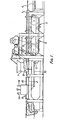
- the stream will pass beneath a hopper 7 of mix and a roller 8 will with the upper pallet faces form a ribbon of mix whose upper surface is of constant contour longitudinally, set by the shape of the roller and whose underface is moulded by the upper faces of the pallets.
- the continuous stream and ribbon pass thereafter to a cutting station 9 where a pair of parallel knives 10,11 extending across the ribbon will cut the ribbon in register with abutting pallet end faces.
- the knives are mounted for vertical reciprocal motion on a knife carriage 12 and are driven by jacks 14 and carriage 12 is mounted for horizontal reciprocal motion on guides 15 by means of a driving rod 16 coupled to a crank 17 driven by the pallet drive mechanism so that the knives will be movable in a direction parallel to the ribbon and achieve ribbon speed at a moment when control valves actuate the knife jacks and each knife is in register with a pair of abutting pallet ends.
- a double Roman tile ' is being produced and two pins 18, vertically reciprocal with the knives, are provided to make nail holes in the ribbon.
- each knife is in register with the abutting faces of a pair of adjacent pallets in the stream.
- the cutting edges of the knives are adjustably mounted longitudinally of their carriage either by making the knives adjustable along guides or by making the knives pivotal.
- the knives can be caused to be positioned in accordance with the sensor position and thereby accurately relative to the pallet and thereby the end faces thereof.
- FIG. 3 One arrangement can be understood from Figure 3 where the pallet stream is shown running left to right.
- the knives 10,11 are pivotable at 20,21, are coupled by a link 22 and are biased clockwise by a spring 23.
- a sensor carriage 24 is mounted on the knife carriage 12 and is movable relative to that carriage by a jack 25, which, because the sensor carriage is mounted on tracks 26 inclined relative to the knife carriage, will result in the sensor carriage not only moving longitudinally relative to the knife carriage but also vertically relative thereto.
- a sensor 28 is pivotally mounted on the sensor carriage, is spring biased anticlockwise as viewed in Figure 3 and is set by a stop 29.
- Extending between the sensor 28 and a knife adjustment member 30 pivotally carried on the knife carriage is a Bowden cable 31 so that, if sensor 28 is pivoted clockwise as viewed in Figure 3 against its bias, a corresponding motion will be imparted to the knives anti-clockwise about their pivots 11,12 by the member 30.
- the sensor 28 projects into the path of a suitable face such as leading face 32 of a web 33 on the underface of each pallet, while in the lower condition of sensor carriage 24 the sensor is clear of the pallets.
- a control switch will, in response to a cam track (not shown) on the machine frame, extend jack 25 and will bring the sensor into the path of a face 32 on a pallet.
- the speed of the knife carriage will be such that the face 32 reaches the sensor and displaces it clockwise (as shown).
- the extent of that displacement will be reproduced at the knife edges and since the face 32 is fixed relative to the ends of its pallet, both knives will fall, when actuated, to the end edges of that pallet.
- the jack 25 will retract, take the sensor beneath the pallet path and the knife carriage will stop and then reverse to its starting position. The cycle will repeat.
- the machine and its drive may be of various forms.
- the sensor carriage could be movable simply vertically without the movement longitudinally of the knife carriage. Also where two knives are provided each may have its own adjustment mechanism and sensor.
- the senor is operative to adjust the position of the knife carriage relative to its driving mechanism, for example by adjusting the length of driving rods 16, in response to the detected actual position of each palet.
- the knives are longitudinally fixed relative to the knife carriage and adjustment of the position of each cut is made by adjusting the position of the carriage itself.
Landscapes
- Engineering & Computer Science (AREA)
- Chemical & Material Sciences (AREA)
- Ceramic Engineering (AREA)
- Mechanical Engineering (AREA)
- Structural Engineering (AREA)
- Manufacturing & Machinery (AREA)
- Devices For Post-Treatments, Processing, Supply, Discharge, And Other Processes (AREA)
- Control Of Cutting Processes (AREA)
Applications Claiming Priority (2)
| Application Number | Priority Date | Filing Date | Title |
|---|---|---|---|
| GB8111179 | 1981-04-09 | ||
| GB8111179 | 1981-04-09 |
Publications (3)
| Publication Number | Publication Date |
|---|---|
| EP0063039A2 true EP0063039A2 (fr) | 1982-10-20 |
| EP0063039A3 EP0063039A3 (en) | 1983-08-17 |
| EP0063039B1 EP0063039B1 (fr) | 1986-12-17 |
Family
ID=10521046
Family Applications (1)
| Application Number | Title | Priority Date | Filing Date |
|---|---|---|---|
| EP19820301872 Expired EP0063039B1 (fr) | 1981-04-09 | 1982-04-08 | Machines à fabriquer des tuiles |
Country Status (3)
| Country | Link |
|---|---|
| EP (1) | EP0063039B1 (fr) |
| DE (1) | DE3274729D1 (fr) |
| GB (1) | GB2097318B (fr) |
Cited By (1)
| Publication number | Priority date | Publication date | Assignee | Title |
|---|---|---|---|---|
| WO1996039289A1 (fr) * | 1995-06-06 | 1996-12-12 | Braas Gmbh | Procede et dispositif de commande de position d'un outil coupant pendant le decoupage d'une bande continue en materiau deformable plastiquement |
Family Cites Families (4)
| Publication number | Priority date | Publication date | Assignee | Title |
|---|---|---|---|---|
| GB284210A (en) * | 1928-01-19 | 1929-02-21 | Keller & Co G M B H C | A method of and means for automatically depositing bricks cut off at right angles from a continuous bar |
| CH182650A (de) * | 1934-10-06 | 1936-02-29 | Frey Ernst | Selbsttätige Vorrichtung zum Schneiden des von einer Tonstrangpresse gelieferten Tonstranges. |
| DE2649409C2 (de) * | 1976-10-29 | 1982-05-13 | Hans Lingl Anlagenbau Und Verfahrenstechnik Gmbh & Co Kg, 7910 Neu-Ulm | Verfahren und Vorrichtung zum Schneiden von Spaltplatten |
| DE2838739C2 (de) * | 1978-09-06 | 1983-03-17 | Hans Lingl Anlagenbau Und Verfahrenstechnik Gmbh & Co Kg, 7910 Neu-Ulm | Vorrichtung zum Schneiden von Ziegelformlingen aus einem Strangstück |
-
1982
- 1982-04-08 EP EP19820301872 patent/EP0063039B1/fr not_active Expired
- 1982-04-08 DE DE8282301872T patent/DE3274729D1/de not_active Expired
- 1982-04-08 GB GB8210396A patent/GB2097318B/en not_active Expired
Cited By (1)
| Publication number | Priority date | Publication date | Assignee | Title |
|---|---|---|---|---|
| WO1996039289A1 (fr) * | 1995-06-06 | 1996-12-12 | Braas Gmbh | Procede et dispositif de commande de position d'un outil coupant pendant le decoupage d'une bande continue en materiau deformable plastiquement |
Also Published As
| Publication number | Publication date |
|---|---|
| GB2097318B (en) | 1985-07-24 |
| EP0063039B1 (fr) | 1986-12-17 |
| GB2097318A (en) | 1982-11-03 |
| DE3274729D1 (en) | 1987-01-29 |
| EP0063039A3 (en) | 1983-08-17 |
Similar Documents
| Publication | Publication Date | Title |
|---|---|---|
| US4345496A (en) | Apparatus for working on successive segments of sheet material | |
| SU506275A3 (ru) | Установка дл резки непрерывно движущегос листового материала | |
| EP0174760B1 (fr) | Procédé et dispositif pour fabriquer des tuiles | |
| US3424357A (en) | Automatically sizing and severing glass sheets | |
| US4699027A (en) | Cable stripping apparatus | |
| US4589456A (en) | Apparatus for producing squared timbers by means of non-chip severing of boards therefrom | |
| US2815074A (en) | Sheet cutting apparatus | |
| EP0228054A2 (fr) | Procédé et dispositif pour couper une chaîne de produits allongés | |
| EP0063039B1 (fr) | Machines à fabriquer des tuiles | |
| US4615249A (en) | Apparatus for trimming stacks of paper sheets or the like | |
| CA1037250A (fr) | Machine a faconner des blocs de beton munie d'un calibre de hauteur | |
| US4026172A (en) | Belt loop trimming apparatus | |
| JPH04310397A (ja) | 紙ウエブの長手方向切断機の円板ナイフ対の切断エッジの位置決め装置 | |
| US4036570A (en) | Cementitious product making system with product height gauging mechanism | |
| KR950012606B1 (ko) | 빵반죽 분할 장치 | |
| EP0139619B1 (fr) | Machine à coudre des livres avec dispositif de séparation automatique des livres | |
| CN111438741A (zh) | 一种控制系统及利用其实现定长切料的方法 | |
| US3233494A (en) | Knife adjusting means for paper cutting machines | |
| EP0561010B1 (fr) | Pliage de feuilles de pâte | |
| CN111496856A (zh) | 一种切割印花一体装置 | |
| US2373941A (en) | Sizing machine | |
| US2691995A (en) | Machine for preclipping veneer sheets to size | |
| US4200020A (en) | Draw cutter | |
| CN111074436A (zh) | 一种物料包边精准剪切机 | |
| US3037412A (en) | Apparatus for shearing continuously advancing strip |
Legal Events
| Date | Code | Title | Description |
|---|---|---|---|
| PUAI | Public reference made under article 153(3) epc to a published international application that has entered the european phase |
Free format text: ORIGINAL CODE: 0009012 |
|
| AK | Designated contracting states |
Designated state(s): DE IT SE |
|
| PUAL | Search report despatched |
Free format text: ORIGINAL CODE: 0009013 |
|
| AK | Designated contracting states |
Designated state(s): DE IT SE |
|
| 17P | Request for examination filed |
Effective date: 19840217 |
|
| GRAA | (expected) grant |
Free format text: ORIGINAL CODE: 0009210 |
|
| AK | Designated contracting states |
Kind code of ref document: B1 Designated state(s): DE IT SE |
|
| ITF | It: translation for a ep patent filed | ||
| REF | Corresponds to: |
Ref document number: 3274729 Country of ref document: DE Date of ref document: 19870129 |
|
| PG25 | Lapsed in a contracting state [announced via postgrant information from national office to epo] |
Ref country code: SE Effective date: 19870409 |
|
| PLBE | No opposition filed within time limit |
Free format text: ORIGINAL CODE: 0009261 |
|
| STAA | Information on the status of an ep patent application or granted ep patent |
Free format text: STATUS: NO OPPOSITION FILED WITHIN TIME LIMIT |
|
| 26N | No opposition filed | ||
| PG25 | Lapsed in a contracting state [announced via postgrant information from national office to epo] |
Ref country code: DE Effective date: 19880101 |
|
| EUG | Se: european patent has lapsed |
Ref document number: 82301872.6 Effective date: 19880906 |