EP0063074A1 - Schnell drehender Rotor insbesondere für Schwungrad - Google Patents
Schnell drehender Rotor insbesondere für Schwungrad Download PDFInfo
- Publication number
- EP0063074A1 EP0063074A1 EP82400574A EP82400574A EP0063074A1 EP 0063074 A1 EP0063074 A1 EP 0063074A1 EP 82400574 A EP82400574 A EP 82400574A EP 82400574 A EP82400574 A EP 82400574A EP 0063074 A1 EP0063074 A1 EP 0063074A1
- Authority
- EP
- European Patent Office
- Prior art keywords
- rim
- arms
- hub
- arm
- loop
- Prior art date
- Legal status (The legal status is an assumption and is not a legal conclusion. Google has not performed a legal analysis and makes no representation as to the accuracy of the status listed.)
- Granted
Links
- 230000000694 effects Effects 0.000 claims abstract description 8
- 238000000034 method Methods 0.000 claims description 20
- 238000004026 adhesive bonding Methods 0.000 claims description 12
- 239000000463 material Substances 0.000 claims description 11
- 230000006978 adaptation Effects 0.000 claims description 7
- 239000002131 composite material Substances 0.000 claims description 6
- OKTJSMMVPCPJKN-UHFFFAOYSA-N Carbon Chemical compound [C] OKTJSMMVPCPJKN-UHFFFAOYSA-N 0.000 claims description 4
- 229910052799 carbon Inorganic materials 0.000 claims description 4
- 229920000642 polymer Polymers 0.000 claims description 4
- ZOXJGFHDIHLPTG-UHFFFAOYSA-N Boron Chemical compound [B] ZOXJGFHDIHLPTG-UHFFFAOYSA-N 0.000 claims description 3
- 229910000831 Steel Inorganic materials 0.000 claims description 3
- 229910052796 boron Inorganic materials 0.000 claims description 3
- 239000011152 fibreglass Substances 0.000 claims description 3
- 238000004519 manufacturing process Methods 0.000 claims description 3
- 239000010959 steel Substances 0.000 claims description 3
- 238000004804 winding Methods 0.000 claims description 3
- 230000006835 compression Effects 0.000 description 4
- 238000007906 compression Methods 0.000 description 4
- 238000010586 diagram Methods 0.000 description 4
- 239000000725 suspension Substances 0.000 description 4
- 102100037651 AP-2 complex subunit sigma Human genes 0.000 description 2
- 101000806914 Homo sapiens AP-2 complex subunit sigma Proteins 0.000 description 2
- 239000000470 constituent Substances 0.000 description 2
- 239000006185 dispersion Substances 0.000 description 2
- 229920002799 BoPET Polymers 0.000 description 1
- 239000005041 Mylar™ Substances 0.000 description 1
- 229920000297 Rayon Polymers 0.000 description 1
- 238000009825 accumulation Methods 0.000 description 1
- 239000000853 adhesive Substances 0.000 description 1
- 230000015572 biosynthetic process Effects 0.000 description 1
- 230000000295 complement effect Effects 0.000 description 1
- 238000009826 distribution Methods 0.000 description 1
- 229920001971 elastomer Polymers 0.000 description 1
- 239000000806 elastomer Substances 0.000 description 1
- 239000003365 glass fiber Substances 0.000 description 1
- 238000005304 joining Methods 0.000 description 1
- 230000002093 peripheral effect Effects 0.000 description 1
- 229920003223 poly(pyromellitimide-1,4-diphenyl ether) Polymers 0.000 description 1
- 235000020004 porter Nutrition 0.000 description 1
- 239000002964 rayon Substances 0.000 description 1
- 238000011084 recovery Methods 0.000 description 1
- 239000011347 resin Substances 0.000 description 1
- 229920005989 resin Polymers 0.000 description 1
- 238000000926 separation method Methods 0.000 description 1
- 230000003068 static effect Effects 0.000 description 1
- 239000003351 stiffener Substances 0.000 description 1
- 238000003786 synthesis reaction Methods 0.000 description 1
Images


Classifications
-
- F—MECHANICAL ENGINEERING; LIGHTING; HEATING; WEAPONS; BLASTING
- F16—ENGINEERING ELEMENTS AND UNITS; GENERAL MEASURES FOR PRODUCING AND MAINTAINING EFFECTIVE FUNCTIONING OF MACHINES OR INSTALLATIONS; THERMAL INSULATION IN GENERAL
- F16F—SPRINGS; SHOCK-ABSORBERS; MEANS FOR DAMPING VIBRATION
- F16F15/00—Suppression of vibrations in systems; Means or arrangements for avoiding or reducing out-of-balance forces, e.g. due to motion
- F16F15/30—Flywheels
- F16F15/305—Flywheels made of plastics, e.g. fibre reinforced plastics [FRP], i.e. characterised by their special construction from such materials
-
- Y—GENERAL TAGGING OF NEW TECHNOLOGICAL DEVELOPMENTS; GENERAL TAGGING OF CROSS-SECTIONAL TECHNOLOGIES SPANNING OVER SEVERAL SECTIONS OF THE IPC; TECHNICAL SUBJECTS COVERED BY FORMER USPC CROSS-REFERENCE ART COLLECTIONS [XRACs] AND DIGESTS
- Y10—TECHNICAL SUBJECTS COVERED BY FORMER USPC
- Y10T—TECHNICAL SUBJECTS COVERED BY FORMER US CLASSIFICATION
- Y10T74/00—Machine element or mechanism
- Y10T74/21—Elements
- Y10T74/2117—Power generating-type flywheel
Definitions
- the elongation in the bar is the third of the elongation in the rim and that consequently one cannot center the rim j by the bar b without obligatorily introducing connections at points A and B, which connections will themselves introduce constraints to ensure the coincidence of the bar-rim contact points.
- the Applicant has developed a technique which has evolved over the course of its studies, in an attempt to definitively resolve the basic structure problem of rotors with high rotational speed, more particularly those intended to be used as as flywheel for energy storage-recovery applications.
- the Applicant firstly revealed for the first time the subcircular rotors in its French patent N ° 70 08 394 of March 9, 1970. It will be recalled briefly that the subcircular concept is based on the following principle: the elongation of the rim j (see FIG. 2) corresponds to a change in shape and not to an increase in diameter, between the initial pseudopolygonal shape at rest P and the outer circle C whose radius is that of the support webs b of the rim. It is thus possible to use for the rim a material which has a greater elongation than that accepted by the arms, either because of their modulus, or because of their shape.
- the stress that the rim applies on the arms can be measured. This depends, among other parameters, on the shape of the rim, once placed on the arm. This results in a certain residual subcircularity at the maximum speed on which the level of compression on the arm depends, as, moreover, appears on reading the diagram in FIG. 2. This compression of the rim on the arms promotes their joining already effected. , for example, by means of a collage.
- FIG. 3 The principle of this solution has been shown diagrammatically in FIG. 3 in which we find the combination of a rim i, a hub m o of at least one connecting arm b with two branches b l , b 2 surrounding said hub .
- Masses ma l and ma 2 are located at the ends of the arm b so that, during rotation, they secure, by pressure, between the arm and the rim, on the one hand, and by traction on the branches between the arm and the hub, on the other hand.
- Anisotropic masses ma n distributed between the arms keep the circularity of the rim constant. Static and dynamic balancing is ensured by the action of electromechanical means e and t acting differently on the masses located ma l , ma 2 , from sensors c a .
- the rotor can be balanced by acting differently by the action of an electromechanical system e, t, from information from sensors c.
- the present invention relates to a process for producing a high-speed rotor more particularly applicable to a flywheel, which constitutes an improved synthesis of the prior systems of the Applicant which have been discussed above.
- This process not only makes it possible to eliminate the drawbacks inherent in each of the prior systems, taken in themselves, but also brings significant advantages which will become apparent as the detailed description of the invention which will be given later.
- the invention also relates to high speed rotors more particularly applicable to flywheels which implement the method according to the invention.
- the method according to the invention essentially consists in centering a rim relative to a hub by means of a certain number of link arms, each of which takes the form of an elongated loop, the two sides of which include rectilinear parts, the internal end of said loop being centered and held against the centrifugal force by a central element forming part of the hub, while the external end of said loop comes to bear constantly against the rim on which it is preferably assembled by gluing, a mass being included inside said outer end of the loop to cause the desired elongation of the loop under the effect of centrifugal force and ensure constant contact between the arm and the rim.
- the link arms are produced by winding, on a suitable mandrel, filamentary composite materials such as glass fibers, carbon, polymers, boron, steel or the like.
- the end mass of the arms is dimensioned such that the end of the arm on the rim side is always in abutment on the rim, which leads to a certain subcircularity of the rim, during rotation, and therefore reinforces the arm-rim connection while maintaining the advantage of having arms remaining in tension.
- connection between the rim and the hub is carried out by means of arms or spokes formed in the manner described below from the main but not exclusive use of materials. filamentary composites.
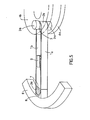
- each arm is made up, as shown in FIGS. 5, 6 and 7, by winding, on a suitable mandrel, of filamentary composite materials such as fiberglass, carbon, polymers, boron, steel , etc. which gives said arm the general shape of an elongated loop whose two sides have rectilinear parts.
- the arm consists of two thin plates 1a and 1b joined at their ends by rounded elements 2a and 2b, it should be noted that these rounded elements can be circular but can advantageously also have an optimized elongated shape, called Horn shape, in order to improve the distribution of mechanical stresses in the connection zone between the arm and the part with which it is in contact.
- the circular crown 5 comprises, at the places where the different arms are to be applied, bearing surfaces 5a which are machined exactly to the internal support form of the end 2b of the arm.
- each arm receives, at the end 2a located on the side of the rim 6, on the one hand an internal part 7 whose mass is defined so as to cause an elongation of the arm adapted to that of the rim 6, on the other hand, a second external part 8 which has the effect of ensuring the adaptation of the shapes allowing a bonding by bonding with the rim 6.
- each of the arms can advantageously be equipped with stiffeners, such as that shown in 9, which have the effect of increasing the stiffness of the attachment of the rim relative to the hub, either in torque if the embodiment of Figure 5 is implemented, or in the axial direction if the embodiment of Figure 6 is applied.
- the central fixing ring consists of an appropriate number of thin elementary rings 9a, 9b ... 9n assembled between them by gluing. Furthermore, each of the elementary rings consists of two thin half-sectors 9a 1 , 9a 2 for the elementary crown 9a and 9b 1 , 9b 2 for the elementary crown 9b.
- the half-sectors constituting an elementary crown are assembled by bonding, it should be noted that the bonding lines 9a 3 of the elementary crown 9a and the bonding lines 9b 3 of the elementary crown 9b are offset by 90 ° with respect to the others when the elementary rings 9a and 9b are assembled together by gluing and so on until the assembly of the elementary crown 9n.
- the number of arms can be adapted to each final configuration of the high speed rotor. Thus, if the rim has a certain height, we will have to use at least two sets of arms, one at each end of the rim, or even a greater number of sets of arms depending on the height of said rim. .
- the height of the rim 6 requires, in this case, the use of two sets of arms 10a and 10b mounted at the two ends of said rim.
- Each set here consists of eight arms paired by pairs of opposite arms: lla, llb, 12a, 12b, 13a, 13b and 14a, 14b.
- Each of the arms here is of the type of FIG. 5 and the central crown here consists of two flanges 4a and 4b joined together by adapter pieces 3, 3a, 3b on which the internal ends 2b of the arms bear.
- the internal flange 4a is part of the hub 16.
- the central shaft 18 is here rotating and integral with said hub 16. Bearings 19 allow the assembly to be mounted in a frame as will be seen in detail.
- central circular fixing ring 5 is continuous.
- This crown which is part of the hub is fixed by fasteners 15 between the shoulder 16a of the middle part of the hub 16 and an outer crown 17.
- the central shaft 18 is again here integral with the hub 16 and bearings 19 allow mounting the whole in a frame.
- Arms of the type of that of FIG. 8 could also be used. This is how one can enhance the characteristic of the invention according to which filamentary composite materials are used for the constitution of the arms. In this eventuality, it is advantageously possible to apply the variant embodiment shown in FIG. 14 in which the end of the arm, on the rim side, is glued directly against the rim and in which materials are advantageously used, the longitudinal elastic modules E and the masses specific e lead to different values of the ratio E for the arms on the one hand and the rim on the other.
- the arm is for example of the type of that shown in FIG. 5 in which the adaptation part 8 is here replaced by a part 20 which includes the end 2a of the arm containing the internal mass 7, this part 20 being provided at its end in contact with the rim 6 with a plate 21 made of a material whose elongation characteristics are such that it can remain on one side secured to the part 20 without tangential elongation at this contact and on the other side remain secured to the rim by accepting its tangential elongation, this regardless of this elongation, throughout the speed range.
- This plate 21 can be made of a resin or an elastomer advantageously reinforced with fiberglass, carbon, polymer, etc.
- the plate 21 is thus glued on one side to the part 20 and on the other on the rim 6.
- the part 20 can be provided at its end with a stack of thin sheets of a material capable of great elongation, such as "Mylar” "Kapton” or similar self-adhesive on its two faces or with gluing of the sheets together and on the rim and the part 20.
- suspension with rotating central shaft 18t in FIGS. 16 and 17 there are two types of suspension, namely: the suspension with rotating central shaft 18t in FIGS. 16 and 17 and the suspension with fixed central shaft 18f in FIG. 18.
- the central shaft 18t which is integral with the hub of the rotor R is mounted on either side of said rotor in the movable elements of two bearings 19 whose fixed elements are integral with two constituent cylinders 22 of the frame.
- the upper one serves as a casing for the electric motor-generator of any known type whose fixed electromagnetic elements 23 are integral with the cylinder 22 and the movable electromagnetic elements 24 integral with the central rotating shaft 18t.
- the motor makes it possible to drive the rotor forming a flywheel at high speed to store energy in kinetic form.
- This kinetic energy is returned in electrical form by the generator or even in mechanical form by the rotating shaft driven by the rotor on its kinetic energy.
- the rotating central shaft 18t on which the rotor R forming the flywheel is fixed is supported in overhang by two bearings 19 mounted at the two ends of a cylinder 22 mounted on the upper part of the frame
- an electric motor generator 23-24 is mounted in said cylinder 22 and the assembly operates in the same manner as the embodiment of FIG. 16 described above.
- the suspension here has a fixed central shaft 18f.
- the shaft 18f is fixed at its two ends in the axis of the frame B, while the rotor R is secured to a central cylinder 22 itself secured to the movable elements of the bearings 19 whose elements fixed are integral with the fixed central shaft 18f.
- the fixed electromagnetic elements 23 of the motor-generator are integral with the fixed central shaft 18t while the mobile electromagnetic elements 24 of this motor are integral with the rotor R.
- FIG. 18 operates in a manner completely similar to that described above.
Landscapes
- Engineering & Computer Science (AREA)
- General Engineering & Computer Science (AREA)
- Physics & Mathematics (AREA)
- Acoustics & Sound (AREA)
- Aviation & Aerospace Engineering (AREA)
- Mechanical Engineering (AREA)
- Connection Of Motors, Electrical Generators, Mechanical Devices, And The Like (AREA)
- Saccharide Compounds (AREA)
- Iron Core Of Rotating Electric Machines (AREA)
Priority Applications (1)
| Application Number | Priority Date | Filing Date | Title |
|---|---|---|---|
| AT82400574T ATE15714T1 (de) | 1981-04-14 | 1982-03-30 | Schnell drehender rotor insbesondere fuer schwungrad. |
Applications Claiming Priority (2)
| Application Number | Priority Date | Filing Date | Title |
|---|---|---|---|
| FR8107465 | 1981-04-14 | ||
| FR8107465A FR2503808A1 (fr) | 1981-04-14 | 1981-04-14 | Procede de realisation d'un rotor a haute vitesse et rotor mettant en oeuvre ledit procede |
Publications (2)
| Publication Number | Publication Date |
|---|---|
| EP0063074A1 true EP0063074A1 (de) | 1982-10-20 |
| EP0063074B1 EP0063074B1 (de) | 1985-09-18 |
Family
ID=9257382
Family Applications (1)
| Application Number | Title | Priority Date | Filing Date |
|---|---|---|---|
| EP82400574A Expired EP0063074B1 (de) | 1981-04-14 | 1982-03-30 | Schnell drehender Rotor insbesondere für Schwungrad |
Country Status (7)
| Country | Link |
|---|---|
| US (1) | US4502349A (de) |
| EP (1) | EP0063074B1 (de) |
| JP (1) | JPS57190145A (de) |
| AT (1) | ATE15714T1 (de) |
| CA (1) | CA1166481A (de) |
| DE (1) | DE3266293D1 (de) |
| FR (1) | FR2503808A1 (de) |
Cited By (1)
| Publication number | Priority date | Publication date | Assignee | Title |
|---|---|---|---|---|
| EP0210563A3 (en) * | 1985-07-23 | 1987-12-02 | E.I. Du Pont De Nemours And Company | Centrifuge rotor |
Families Citing this family (15)
| Publication number | Priority date | Publication date | Assignee | Title |
|---|---|---|---|---|
| FR2574491B1 (fr) * | 1984-12-07 | 1989-01-06 | Europ Agence Spatiale | Roue de stockage d'energie |
| US4817453A (en) * | 1985-12-06 | 1989-04-04 | E. I. Dupont De Nemours And Company | Fiber reinforced centrifuge rotor |
| US4991462A (en) * | 1985-12-06 | 1991-02-12 | E. I. Du Pont De Nemours And Company | Flexible composite ultracentrifuge rotor |
| US4835827A (en) * | 1987-09-08 | 1989-06-06 | United Technologies Corporation | Method of balancing a rotor |
| US5562584A (en) * | 1989-08-02 | 1996-10-08 | E. I. Du Pont De Nemours And Company | Tension band centrifuge rotor |
| US5545118A (en) * | 1989-08-02 | 1996-08-13 | Romanauskas; William A. | Tension band centrifuge rotor |
| EP0572565A4 (en) * | 1991-03-01 | 1994-08-10 | Du Pont | Tension band centrifuge rotor |
| US5452625A (en) * | 1993-09-29 | 1995-09-26 | United Technologies Corporation | Energy storage flywheel device |
| US8147393B2 (en) * | 2009-01-19 | 2012-04-03 | Fiberlite Centrifuge, Llc | Composite centrifuge rotor |
| US8147392B2 (en) * | 2009-02-24 | 2012-04-03 | Fiberlite Centrifuge, Llc | Fixed angle centrifuge rotor with helically wound reinforcement |
| US8328708B2 (en) * | 2009-12-07 | 2012-12-11 | Fiberlite Centrifuge, Llc | Fiber-reinforced swing bucket centrifuge rotor and related methods |
| CN102624141B (zh) * | 2011-01-28 | 2014-03-19 | 深圳飞能能源有限公司 | 高速飞轮电池的转子 |
| CN102624110B (zh) * | 2011-01-28 | 2013-12-04 | 深圳飞能能源有限公司 | 高速电机 |
| US10050491B2 (en) | 2014-12-02 | 2018-08-14 | Management Services Group, Inc. | Devices and methods for increasing energy and/or power density in composite flywheel energy storage systems |
| WO2020167864A2 (en) * | 2019-02-11 | 2020-08-20 | Amber Kinetics, Inc. | Stacked lamination rotor |
Citations (6)
| Publication number | Priority date | Publication date | Assignee | Title |
|---|---|---|---|---|
| FR2082274A5 (en) * | 1970-03-09 | 1971-12-10 | Aerospatiale | Ultracentrifuge rotor - hub spider and wall assembly of high rigidity to weight ratio |
| FR2282737A1 (fr) * | 1974-08-22 | 1976-03-19 | Inst Rech Transports | Structure de roue adaptee aux grandes vitesses angulaires et mode de fabrication de celle-ci |
| US4176563A (en) * | 1976-10-27 | 1979-12-04 | Electric Power Research Institute | Inertial energy storage rotor with tension-balanced catenary spokes |
| FR2434968A1 (fr) * | 1978-08-29 | 1980-03-28 | Aerospatiale | Procede inertiel de centrale d'une jante constamment circulaire sur son moyeu et dispositif rotatif correspondant |
| FR2436267A1 (fr) * | 1978-09-13 | 1980-04-11 | Swartout Bruce | Jante pour volant d'inertie |
| FR2458005A1 (fr) * | 1979-05-29 | 1980-12-26 | Aerospatiale | Procede de realisation d'un rotor de type subcirculaire et rotors mettant en oeuvre ce procede, notamment rotors de volant d'inertie |
Family Cites Families (3)
| Publication number | Priority date | Publication date | Assignee | Title |
|---|---|---|---|---|
| CH447041A (fr) * | 1965-06-21 | 1968-03-15 | Ebauches Sa | Dispositif d'équilibrage d'un volant rotatif ou oscillant de mouvement d'horlogerie |
| US3964341A (en) * | 1974-03-18 | 1976-06-22 | The Johns Hopkins University | Multi-ring filament rotor |
| US4036080A (en) * | 1974-11-29 | 1977-07-19 | The Garrett Corporation | Multi-rim flywheel |
-
1981
- 1981-04-14 FR FR8107465A patent/FR2503808A1/fr active Granted
-
1982
- 1982-03-30 DE DE8282400574T patent/DE3266293D1/de not_active Expired
- 1982-03-30 EP EP82400574A patent/EP0063074B1/de not_active Expired
- 1982-03-30 AT AT82400574T patent/ATE15714T1/de not_active IP Right Cessation
- 1982-03-31 CA CA000400041A patent/CA1166481A/en not_active Expired
- 1982-04-09 US US06/367,124 patent/US4502349A/en not_active Expired - Fee Related
- 1982-04-13 JP JP57061655A patent/JPS57190145A/ja active Pending
Patent Citations (6)
| Publication number | Priority date | Publication date | Assignee | Title |
|---|---|---|---|---|
| FR2082274A5 (en) * | 1970-03-09 | 1971-12-10 | Aerospatiale | Ultracentrifuge rotor - hub spider and wall assembly of high rigidity to weight ratio |
| FR2282737A1 (fr) * | 1974-08-22 | 1976-03-19 | Inst Rech Transports | Structure de roue adaptee aux grandes vitesses angulaires et mode de fabrication de celle-ci |
| US4176563A (en) * | 1976-10-27 | 1979-12-04 | Electric Power Research Institute | Inertial energy storage rotor with tension-balanced catenary spokes |
| FR2434968A1 (fr) * | 1978-08-29 | 1980-03-28 | Aerospatiale | Procede inertiel de centrale d'une jante constamment circulaire sur son moyeu et dispositif rotatif correspondant |
| FR2436267A1 (fr) * | 1978-09-13 | 1980-04-11 | Swartout Bruce | Jante pour volant d'inertie |
| FR2458005A1 (fr) * | 1979-05-29 | 1980-12-26 | Aerospatiale | Procede de realisation d'un rotor de type subcirculaire et rotors mettant en oeuvre ce procede, notamment rotors de volant d'inertie |
Cited By (1)
| Publication number | Priority date | Publication date | Assignee | Title |
|---|---|---|---|---|
| EP0210563A3 (en) * | 1985-07-23 | 1987-12-02 | E.I. Du Pont De Nemours And Company | Centrifuge rotor |
Also Published As
| Publication number | Publication date |
|---|---|
| ATE15714T1 (de) | 1985-10-15 |
| JPS57190145A (en) | 1982-11-22 |
| DE3266293D1 (en) | 1985-10-24 |
| FR2503808A1 (fr) | 1982-10-15 |
| EP0063074B1 (de) | 1985-09-18 |
| US4502349A (en) | 1985-03-05 |
| FR2503808B1 (de) | 1983-06-24 |
| CA1166481A (en) | 1984-05-01 |
Similar Documents
| Publication | Publication Date | Title |
|---|---|---|
| EP0063074B1 (de) | Schnell drehender Rotor insbesondere für Schwungrad | |
| EP3212960B1 (de) | Schwungrad für energiespeicherung | |
| EP0608675B1 (de) | Elektrischer Motor mit hoher Drehgeschwindigkeit und hoher Leistung | |
| EP0493145A1 (de) | Rotornabe eines Drehflügelflugzeuges | |
| WO2021176058A1 (fr) | Rotor pour machine electromagnetique a flux axial | |
| FR2653405A1 (fr) | Dispositif visco-elastique rotatif de rappel elastique et d'amortissement en trainee pour pale de rotor de giravion, et tete de rotor le comportant. | |
| FR3027468A1 (fr) | Rotor discoide a structure composite | |
| WO2022200379A1 (fr) | Rotor pour machine électrique à flux axial, des procédés d'assemblage et de démontage d'un tel rotor | |
| FR3083023A1 (fr) | Rotor pour moteur ou generatrice electromagnetique avec branches effiles | |
| EP0187080B1 (de) | Energiespeicherndes Rad | |
| FR2629958A1 (fr) | Rotor pour machine electrique excitee par aimants permanents | |
| FR2695767A1 (fr) | Moteur piézo-électrique rotatif présentant une liaison stator-boîtier améliorée. | |
| EP0308369A1 (de) | Dauermagnetläufer | |
| EP2019220A1 (de) | Flexiplatte, elastische Kupplung mit einer solchen Flexiplatte, Flansch mit einer solchen Kupplung, Welle mit einer solchen Flansch | |
| EP0538088B1 (de) | Mehrblätterrotor, insbesondere eines Hubschrauberdrehmomentausgleichsheckrotor, und sein Herstellungsverfahren | |
| WO2019073128A1 (fr) | Rotor pour moteur ou génératrice électromagnétique à rigidité diminuée | |
| FR3031497A1 (fr) | Rotor de giravion comportant un moyeu en materiaux composites issus de tissus de fibres de carbone poudrees d'une resine thermoplastique | |
| FR3033095A1 (fr) | Dispositif de fixation des aimants dans un rotor de machine electrique discoide. | |
| CH643041A5 (fr) | Rotor subcirculaire. | |
| EP2160584B1 (de) | Befestigungsmittel für getriebewelle und auswuchtblock mit derartigem mittel | |
| WO2024079165A1 (fr) | Rotor pour moteur électromagnétique avec structures d'aimant en deux parties | |
| EP3830936A1 (de) | Klauenläufer mit zwischenklauenmagnetelementen für eine elektrische drehmaschine | |
| WO2025210265A1 (fr) | Rotor de machine électrique comprenant des cales pour le maintien d'aimants permanents | |
| WO2025252854A1 (fr) | Assemblage rotorique de machine a flux axial protege par un enroulement filamentaire et procede de fabrication d'un tel assemblage | |
| FR2894733A1 (fr) | Procede de fabrication d'un rotor et rotor de machine tournante electrique. |
Legal Events
| Date | Code | Title | Description |
|---|---|---|---|
| PUAI | Public reference made under article 153(3) epc to a published international application that has entered the european phase |
Free format text: ORIGINAL CODE: 0009012 |
|
| AK | Designated contracting states |
Designated state(s): AT BE CH DE GB IT NL SE |
|
| 17P | Request for examination filed |
Effective date: 19821129 |
|
| ITF | It: translation for a ep patent filed | ||
| GRAA | (expected) grant |
Free format text: ORIGINAL CODE: 0009210 |
|
| AK | Designated contracting states |
Designated state(s): AT BE CH DE GB IT LI NL SE |
|
| REF | Corresponds to: |
Ref document number: 15714 Country of ref document: AT Date of ref document: 19851015 Kind code of ref document: T |
|
| REF | Corresponds to: |
Ref document number: 3266293 Country of ref document: DE Date of ref document: 19851024 |
|
| PLBE | No opposition filed within time limit |
Free format text: ORIGINAL CODE: 0009261 |
|
| STAA | Information on the status of an ep patent application or granted ep patent |
Free format text: STATUS: NO OPPOSITION FILED WITHIN TIME LIMIT |
|
| 26N | No opposition filed | ||
| PGFP | Annual fee paid to national office [announced via postgrant information from national office to epo] |
Ref country code: SE Payment date: 19910312 Year of fee payment: 10 |
|
| PGFP | Annual fee paid to national office [announced via postgrant information from national office to epo] |
Ref country code: GB Payment date: 19910321 Year of fee payment: 10 |
|
| ITTA | It: last paid annual fee | ||
| PGFP | Annual fee paid to national office [announced via postgrant information from national office to epo] |
Ref country code: NL Payment date: 19910331 Year of fee payment: 10 |
|
| PGFP | Annual fee paid to national office [announced via postgrant information from national office to epo] |
Ref country code: CH Payment date: 19910411 Year of fee payment: 10 |
|
| PGFP | Annual fee paid to national office [announced via postgrant information from national office to epo] |
Ref country code: DE Payment date: 19910514 Year of fee payment: 10 Ref country code: BE Payment date: 19910514 Year of fee payment: 10 |
|
| PGFP | Annual fee paid to national office [announced via postgrant information from national office to epo] |
Ref country code: AT Payment date: 19910528 Year of fee payment: 10 |
|
| PG25 | Lapsed in a contracting state [announced via postgrant information from national office to epo] |
Ref country code: GB Effective date: 19920330 Ref country code: AT Effective date: 19920330 |
|
| PG25 | Lapsed in a contracting state [announced via postgrant information from national office to epo] |
Ref country code: SE Effective date: 19920331 Ref country code: LI Effective date: 19920331 Ref country code: CH Effective date: 19920331 Ref country code: BE Effective date: 19920331 |
|
| BERE | Be: lapsed |
Owner name: SOC. NATIONALE INDUSTRIELLE AEROSPATIALE Effective date: 19920331 |
|
| PG25 | Lapsed in a contracting state [announced via postgrant information from national office to epo] |
Ref country code: NL Effective date: 19921001 |
|
| NLV4 | Nl: lapsed or anulled due to non-payment of the annual fee | ||
| GBPC | Gb: european patent ceased through non-payment of renewal fee | ||
| REG | Reference to a national code |
Ref country code: CH Ref legal event code: PL |
|
| PG25 | Lapsed in a contracting state [announced via postgrant information from national office to epo] |
Ref country code: DE Effective date: 19921201 |
|
| EUG | Se: european patent has lapsed |
Ref document number: 82400574.8 Effective date: 19921005 |