EP0063078A1 - Schwingungsdämpfungsvorrichtung für Hubschrauber - Google Patents
Schwingungsdämpfungsvorrichtung für Hubschrauber Download PDFInfo
- Publication number
- EP0063078A1 EP0063078A1 EP82400584A EP82400584A EP0063078A1 EP 0063078 A1 EP0063078 A1 EP 0063078A1 EP 82400584 A EP82400584 A EP 82400584A EP 82400584 A EP82400584 A EP 82400584A EP 0063078 A1 EP0063078 A1 EP 0063078A1
- Authority
- EP
- European Patent Office
- Prior art keywords
- fuselage
- gearbox
- bars
- helicopter
- supports
- Prior art date
- Legal status (The legal status is an assumption and is not a legal conclusion. Google has not performed a legal analysis and makes no representation as to the accuracy of the status listed.)
- Granted
Links
Images

Classifications
-
- B—PERFORMING OPERATIONS; TRANSPORTING
- B64—AIRCRAFT; AVIATION; COSMONAUTICS
- B64C—AEROPLANES; HELICOPTERS
- B64C27/00—Rotorcraft; Rotors peculiar thereto
- B64C27/001—Vibration damping devices
-
- B—PERFORMING OPERATIONS; TRANSPORTING
- B64—AIRCRAFT; AVIATION; COSMONAUTICS
- B64C—AEROPLANES; HELICOPTERS
- B64C27/00—Rotorcraft; Rotors peculiar thereto
- B64C27/001—Vibration damping devices
- B64C2027/002—Vibration damping devices mounted between the rotor drive and the fuselage
-
- B—PERFORMING OPERATIONS; TRANSPORTING
- B64—AIRCRAFT; AVIATION; COSMONAUTICS
- B64C—AEROPLANES; HELICOPTERS
- B64C27/00—Rotorcraft; Rotors peculiar thereto
- B64C27/001—Vibration damping devices
- B64C2027/005—Vibration damping devices using suspended masses
Definitions
- the invention relates to an anti-vibration suspension device for the main gearbox of a helicopter, comprising two deformable supports of generally elongated shape, arranged parallel between two and to the longitudinal axis of the fuselage of the helicopter on the on the other side of the gearbox, to which they are connected, being moreover articulated each in two strong points of the fuselage structure and carrying at each of their free ends a beating mass, while said supports, their points of articulation to the fuselage and the flying masses they carry are arranged symmetrically with respect to the longitudinal plane as well as to the transverse plane passing through the axis of the helicopter rotor.
- a suspension device of this kind is known from French patent No. 78/26 242 (Boeing).
- a set of weighted levers and associated elastic arms connects the gearbox to the fuselage of the helicopter by a support system comprising, for each lever and associated elastic arm, two articulations, the first connecting the transmission to the lever around a first pivot axis and the second connecting the fuselage to the lever around a second pivot axis offset from the first along the length of the lever, one of the pivot axes being located practically at the one end of the lever.
- a support system comprising, for each lever and associated elastic arm, two articulations, the first connecting the transmission to the lever around a first pivot axis and the second connecting the fuselage to the lever around a second pivot axis offset from the first along the length of the lever, one of the pivot axes being located practically at the one end of the lever.
- To this pair of supports of complex structure must also be added complementary springs to eliminate the harmful effects of certain vibration forces appearing due to the offset between the
- each support is constituted by a bar preferably rectilinear, made in one piece and rigidly fixed in its central part at the bottom of the gearbox, this bar comprising flexible parts between its central part and its articulations at the strong points of the fuselage, and, beyond these articulations, relatively rigid parts, weighted, at their end, with the aforementioned beating masses , and to this pair of bars is associated a vertical connecting rod located substantially on the axis of the rotor and connected by articulations on the one hand to the bottom of the gearbox and on the other hand to the structure of the fuselage, the suspension device being essentially constituted by said pair of bars and said rod and being entirely located between the bottom of the helicop's transmission box tère and its fuselage.
- the device according to the invention has the advantage of being simple, light and inexpensive. It also eliminates the set of oblique bars usually provided between the fuselage and the head of the gearbox to keep the latter in position.
- the bars have in their different parts a section of variable size depending on the forces to be supported and the flexibility required.
- These bars can also be made of composite material based on longitudinal glass fibers and resin.
- the device for connecting the transmission box to the fuselage by interposing between the lower end of the lift rod and the resistant structure of the fuselage an additional filtering arrangement.
- This can be constituted by an elastic bar arranged horizontally, in the center of which is articulated the rod and which can bend in a vertical plane on two supports fixed to the structure of the fuselage and located on either side of the center of the bar, the latter extending beyond each of its supports by forming two levers weighted with a mass at their end.
- This additional arrangement is dimensioned to transmit the static vertical forces from the bottom of the gearbox to the fuselage and simultaneously filter the dynamic vertical forces because they cause, by bending of the bar, movements of the end masses which, at their turn, create inertial efforts whose reactions to the right of the fixations on the structure are opposite direction to elastic reactions.
- the connecting joints of the aforementioned link at the bottom of the gearbox and to the fuselage structure - either directly or through the aforementioned filtering arrangement - are preferably ball joints.
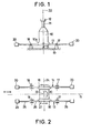
- FIGS. 1 and 2 show the main gearbox 10 of a helicopter, disposed between a propulsion unit not shown and the shaft 11 of the rotor, the hub of which is shown diagrammatically at 12.
- the base 10a of the casing of the gearbox is rigidly fixed by its lateral edges to two bars 13 and 14 parallel to each other and to the longitudinal axis 15 of the device. These two bars are in the present example rigidly linked to the base 10a of the box by bolts 16 on the one hand and are articulated, on the other hand, each in two strong points 17 and 18 of the structure 19 of the fuselage of the device. They are also equipped at their free ends with swinging masses 20.
- FIG. 2 shows that the arrangement is entirely symmetrical with respect to the longitudinal plane defined by the axis 15 and to the transverse plane 24 passing through the axis of rotation 22 of the rotor, axis on which are elements 10, 11 and 12 are aligned.
- the transmission box is connected to the structure 19 of the fuselage by means of an articulated link 21, disposed centrally between the bottom 10a of said box and said structure 19, on the axis 22 of the rotor.
- This link 21 provides a firm and rigid connection in the vertical direction and transmits directly to the structure 19 the forces of lift of the rotor so that they do not stress the bars 13, 14 in bending.
- the two bars 13 and 14 preferably made of a composite material such as glass fibers coated in a thermoset resin, transmit the reaction of the drive torque of the rotor of the gearbox 10 to the structure 19 by traction-compression ( Figure 2) and without any relative rotation of a bar relative to the other.
- Figure 2 traction-compression
- the longitudinal and transverse tilting moments of the box 10, shaft 11 and hub 12 rotor assembly due to the forces or moments generated in the plane of the rotor, cause the bars 13 and 14 to bend. masses of ends 20 of large displacements which, in turn, generate inertial forces whose reactions at the fixing points 17 and 18 of the bars 13, 14 on the structure 19 are in opposite directions to the elastic reactions.
- each of the two bars 13 and 14 is constituted by two identical half-bars, symmetrical with respect to the transverse plane 24.
- Each half-bar comprises three parts, namely an external part 25 to the support 18, which is equipped with a swinging mass 20 at its end and offers the rigidity just necessary to carry the latter, a part 26 included between the articulated support 18 and the gearbox 10, which constitutes the flexible and deformable part under the action tilting forces exerted by said gearbox, and a part 27 for fixing to the bottom 10a of the gearbox.
- the thickness and the constituent materials of the parts 26 and 27 of the bars are chosen so that the part 26 can flex under the effect of the tilting moments.
- the resistance of these two parts, located between the bottom 10a of the gearbox and the support on the structure 19, must be sufficient for them to be able to transmit both the traction or compression forces generated by the torque d drive the rotor and withstand the bending and tilting moments, static and dynamic.
- the end part 25 of the bars must support only the alternating moments due to the inertia developed by the beating mass 20 which it carries, and its section is less important than the section of the parts 26 and 27, so as to allow to the masses 20 important relative movements, favoring the creation of high inertia forces.
- the dimensioning of the bars 13, 14, the distances between the bottom 10a of the main gearbox, the points of articulation of said bars to the structure 19 and the masses 20, as well as the importance of these masses are chosen such that so that there is a balance between reactions of various kinds at the points of attachment to the structure.
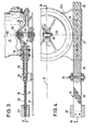
- the bars 13 and 14 are made of flat ribbons 30, 31 rovings extending from one end to the other of a bar. Between the support points 17 and 18 of each bar on the structure 19, the latter is reinforced by interposition between the flat ribbons 30 and 31 of a filling 32 of "compound" made of glass fibers embedded in resin.
- the vertical link 21 is articulated on the one hand on the bottom 10a of the gearbox 10 by means of a ball joint 28 and on the top of the structure 19 also by means of a ball joint 23.
- a filter assembly 38 is added, as indicated in FIG. 5, between the base of the vertical link 21 and the fuselage 19.
- annex constituted by a bar 33 produced for example in laminate of glass fibers and resin, supported by two articulation bearings 34 on two. supports 35 fixed to the fuselage 19, and extended on either side of these supports by two levers 36 each carrying at their end a beating mass 37, the assembly being symmetrical with respect to the axis 22.
- the static vertical forces from the rotor essentially the lift of the rotor, are collected in bending by the bar 33 and transmitted to the fuselage 19 by the two supports 35.
- the dynamic vertical forces cause an alternating bending of the bar 33 and a setting in motion. oscillating masses 37 around the articulations 34 introducing into these articulations vertical inertia forces in the opposite direction to the elastic reactions, which practically cancel the latter, thus filtering the vertical vibrations coming from the rotor.
Landscapes
- Engineering & Computer Science (AREA)
- Mechanical Engineering (AREA)
- Aviation & Aerospace Engineering (AREA)
- Vibration Prevention Devices (AREA)
- Vehicle Body Suspensions (AREA)
- Apparatuses For Generation Of Mechanical Vibrations (AREA)
Applications Claiming Priority (2)
| Application Number | Priority Date | Filing Date | Title |
|---|---|---|---|
| FR8107270 | 1981-04-10 | ||
| FR8107270A FR2503663A1 (fr) | 1981-04-10 | 1981-04-10 | Dispositif de suspension antivibratoire pour helicoptere |
Publications (2)
| Publication Number | Publication Date |
|---|---|
| EP0063078A1 true EP0063078A1 (de) | 1982-10-20 |
| EP0063078B1 EP0063078B1 (de) | 1984-08-08 |
Family
ID=9257266
Family Applications (1)
| Application Number | Title | Priority Date | Filing Date |
|---|---|---|---|
| EP82400584A Expired EP0063078B1 (de) | 1981-04-10 | 1982-03-31 | Schwingungsdämpfungsvorrichtung für Hubschrauber |
Country Status (5)
| Country | Link |
|---|---|
| US (1) | US4458861A (de) |
| EP (1) | EP0063078B1 (de) |
| JP (1) | JPS57191196A (de) |
| DE (1) | DE3260522D1 (de) |
| FR (1) | FR2503663A1 (de) |
Cited By (2)
| Publication number | Priority date | Publication date | Assignee | Title |
|---|---|---|---|---|
| DE19832697A1 (de) * | 1998-07-21 | 2000-02-03 | Eurocopter Deutschland | Vorrichtung und Verfahren zur Reduktion von Schwingungen längs einer Schwingungsausbreitung, insbesondere in einem Hubschrauber |
| US10384770B2 (en) * | 2014-07-04 | 2019-08-20 | Leonardo S.P.A. | Helicopter with noise and vibration damping transmission mounting |
Families Citing this family (6)
| Publication number | Priority date | Publication date | Assignee | Title |
|---|---|---|---|---|
| IT1228988B (it) * | 1989-04-11 | 1991-07-12 | Fima Spa | Dispositivo dissipatore d'energia a comportamento elastoplastico, particolarmente per impiego in strutture antisismiche. |
| US5118051A (en) * | 1989-04-18 | 1992-06-02 | United Technologies Corporation | Roll vibration absorber |
| US5154371A (en) * | 1991-04-10 | 1992-10-13 | United Technologies Corporation | Main rotor assembly support truss |
| FR2758602B1 (fr) * | 1997-01-17 | 1999-04-02 | Hutchinson | Dispositif de suspension elastique pour tubulure d'echappement |
| FR2939409B1 (fr) * | 2008-12-08 | 2011-02-11 | Airbus France | Systeme de fixation entre deux composants tels qu'un moteur d'aeronef et son mat d'accrochage |
| EP3112721B1 (de) | 2015-06-29 | 2018-04-25 | AIRBUS HELICOPTERS DEUTSCHLAND GmbH | Schwingungsisolierende vorrichtung für elastische kupplung zweier bauteile |
Citations (4)
| Publication number | Priority date | Publication date | Assignee | Title |
|---|---|---|---|---|
| FR2232481A1 (de) * | 1973-06-08 | 1975-01-03 | Aerospatiale | |
| FR2363737A1 (fr) * | 1976-09-07 | 1978-03-31 | Boeing Co | Systeme d'isolation de vibrations |
| FR2402808A1 (fr) * | 1977-09-13 | 1979-04-06 | Boeing Co | Systeme d'isolation des vibrations |
| FR2474996A1 (fr) * | 1980-02-05 | 1981-08-07 | Aerospatiale | Dispositif de suspension antiresonnante pour helicoptere |
Family Cites Families (3)
| Publication number | Priority date | Publication date | Assignee | Title |
|---|---|---|---|---|
| US3845917A (en) * | 1971-10-18 | 1974-11-05 | Textron Inc | Helicopter vibration isolation |
| US3972491A (en) * | 1975-07-14 | 1976-08-03 | United Technologies Corporation | Two-position helicopter main rotor |
| US4372431A (en) * | 1979-11-05 | 1983-02-08 | The Boeing Company | Six axis vibration isolation system |
-
1981
- 1981-04-10 FR FR8107270A patent/FR2503663A1/fr active Granted
-
1982
- 1982-03-31 EP EP82400584A patent/EP0063078B1/de not_active Expired
- 1982-03-31 DE DE8282400584T patent/DE3260522D1/de not_active Expired
- 1982-04-01 US US06/364,227 patent/US4458861A/en not_active Expired - Lifetime
- 1982-04-09 JP JP57058415A patent/JPS57191196A/ja active Granted
Patent Citations (4)
| Publication number | Priority date | Publication date | Assignee | Title |
|---|---|---|---|---|
| FR2232481A1 (de) * | 1973-06-08 | 1975-01-03 | Aerospatiale | |
| FR2363737A1 (fr) * | 1976-09-07 | 1978-03-31 | Boeing Co | Systeme d'isolation de vibrations |
| FR2402808A1 (fr) * | 1977-09-13 | 1979-04-06 | Boeing Co | Systeme d'isolation des vibrations |
| FR2474996A1 (fr) * | 1980-02-05 | 1981-08-07 | Aerospatiale | Dispositif de suspension antiresonnante pour helicoptere |
Cited By (3)
| Publication number | Priority date | Publication date | Assignee | Title |
|---|---|---|---|---|
| DE19832697A1 (de) * | 1998-07-21 | 2000-02-03 | Eurocopter Deutschland | Vorrichtung und Verfahren zur Reduktion von Schwingungen längs einer Schwingungsausbreitung, insbesondere in einem Hubschrauber |
| DE19832697C2 (de) * | 1998-07-21 | 2000-11-16 | Eurocopter Deutschland | Vorrichtung und Verfahren zur Reduktion von Schwingungen längs einer Schwingungsausbreitung, insbesondere in einem Hubschrauber |
| US10384770B2 (en) * | 2014-07-04 | 2019-08-20 | Leonardo S.P.A. | Helicopter with noise and vibration damping transmission mounting |
Also Published As
| Publication number | Publication date |
|---|---|
| FR2503663A1 (fr) | 1982-10-15 |
| DE3260522D1 (en) | 1984-09-13 |
| JPS57191196A (en) | 1982-11-24 |
| FR2503663B1 (de) | 1984-05-04 |
| EP0063078B1 (de) | 1984-08-08 |
| JPH049719B2 (de) | 1992-02-21 |
| US4458861A (en) | 1984-07-10 |
Similar Documents
| Publication | Publication Date | Title |
|---|---|---|
| EP0034092B1 (de) | Antiresonanz-Aufhängevorrichtung für Hubschrauber | |
| EP0058117B1 (de) | Vereinfachte schwingungsgedämpfte Aufhängungsvorrichtung für Hubschrauber | |
| CA1321378C (fr) | Tete de rotor de giravion a tirants interpales de rappel elastique avec amortissement incorpore | |
| EP0156705B1 (de) | Schwinghebelaufhängung für einen Fahrzeugradsatz mit zwei Rädern und Zusammenbau der Parallelröhren für eine derartige Aufhängung | |
| CA2071390C (fr) | Dispositif de liaison elastique entre deux pieces, et aeronef a voilure tournante comportant ledit dispositif | |
| EP0021901B1 (de) | Kompakt-Gelenkrotor für Drehflüger | |
| EP0488845B1 (de) | Anti-Resonanz-Aufhängungsvorrichtung eines Hubschraubers | |
| EP1400398B1 (de) | Vorrichtung und System zum Filtrieren der Schwingungen einer Passagierhalterung, und mit solchem System ausgestatteter Passagierhalterung. | |
| FR2516891A1 (fr) | Rotor pour giravions, a articulations integrees dans le pied de pale | |
| EP0213016B1 (de) | Mast-Nabeneinheit und Drehflügerrotorkopf mit einer solchen Einheit | |
| EP0588684B1 (de) | Aufhängungssystem zum Tragen von Ausrüstung an einem Fahrzeugaufbau | |
| EP0063078B1 (de) | Schwingungsdämpfungsvorrichtung für Hubschrauber | |
| EP0097540A1 (de) | Längslenkeraufhängung für eine Zweiräderachse eines Kraftfahrzeuges mit Querstabilisator und elastischer Federung | |
| EP2316730B1 (de) | Vorrichtung zum Filtern der Vibrationen die von einem Flugzeug, insbesondere einem Helikopter, an ein Gerät übertragen werden | |
| EP0208608B1 (de) | Antiresonanzaufhängungsvorrichtung mit sechs Freiheitsgraden für einen Hubschrauber | |
| EP0718187B1 (de) | Lagerungsvorrichtung mit bidirektionalem Schwingungsdämpfer für einen Hubschrauberrotor | |
| FR2728538A1 (fr) | Dispositif de suspension anti-vibratoire de rotor d'helicoptere | |
| FR2513587A1 (fr) | Dispositif de support pour un ensemble moteur de vehicule | |
| FR2787762A1 (fr) | Dispositif de suspension antivibratoire avec ressort en torsion, pour helicoptere | |
| FR2678579A1 (fr) | Tete de rotor de giravion, rigide en trainee et articulee en pas et battement. | |
| FR2779117A1 (fr) | Pale pour un rotor sans palier d'un helicoptere | |
| EP1719700B1 (de) | Haltesvorrichtung für eine Flugzeugbatterie | |
| FR2585327A1 (fr) | Dispositif a tige de tension/compression pour amortir les oscillations des pales de rotor d'helicoptere | |
| EP1662166B1 (de) | Vorrichtung zum Filtern von Schwingungen zwischen zwei Körpern und Anwendungen | |
| FR2777861A1 (fr) | Dispositif simplifie de suspension antivibratoire pour helicoptere |
Legal Events
| Date | Code | Title | Description |
|---|---|---|---|
| PUAI | Public reference made under article 153(3) epc to a published international application that has entered the european phase |
Free format text: ORIGINAL CODE: 0009012 |
|
| 17P | Request for examination filed |
Effective date: 19820331 |
|
| AK | Designated contracting states |
Designated state(s): DE GB IT |
|
| ITF | It: translation for a ep patent filed | ||
| GRAA | (expected) grant |
Free format text: ORIGINAL CODE: 0009210 |
|
| AK | Designated contracting states |
Designated state(s): DE GB IT |
|
| REF | Corresponds to: |
Ref document number: 3260522 Country of ref document: DE Date of ref document: 19840913 |
|
| PLBE | No opposition filed within time limit |
Free format text: ORIGINAL CODE: 0009261 |
|
| STAA | Information on the status of an ep patent application or granted ep patent |
Free format text: STATUS: NO OPPOSITION FILED WITHIN TIME LIMIT |
|
| 26N | No opposition filed | ||
| PGFP | Annual fee paid to national office [announced via postgrant information from national office to epo] |
Ref country code: GB Payment date: 19910222 Year of fee payment: 10 |
|
| ITTA | It: last paid annual fee | ||
| PGFP | Annual fee paid to national office [announced via postgrant information from national office to epo] |
Ref country code: DE Payment date: 19910511 Year of fee payment: 10 |
|
| PG25 | Lapsed in a contracting state [announced via postgrant information from national office to epo] |
Ref country code: GB Effective date: 19920331 |
|
| GBPC | Gb: european patent ceased through non-payment of renewal fee | ||
| PG25 | Lapsed in a contracting state [announced via postgrant information from national office to epo] |
Ref country code: DE Effective date: 19921201 |