EP0063217A1 - Dispositif pour emmagasiner des câbles électriques - Google Patents
Dispositif pour emmagasiner des câbles électriques Download PDFInfo
- Publication number
- EP0063217A1 EP0063217A1 EP82101223A EP82101223A EP0063217A1 EP 0063217 A1 EP0063217 A1 EP 0063217A1 EP 82101223 A EP82101223 A EP 82101223A EP 82101223 A EP82101223 A EP 82101223A EP 0063217 A1 EP0063217 A1 EP 0063217A1
- Authority
- EP
- European Patent Office
- Prior art keywords
- shaft
- cable
- storage space
- rollers
- drive
- Prior art date
- Legal status (The legal status is an assumption and is not a legal conclusion. Google has not performed a legal analysis and makes no representation as to the accuracy of the status listed.)
- Granted
Links
- 238000010438 heat treatment Methods 0.000 description 2
- 230000006698 induction Effects 0.000 description 2
- 238000004519 manufacturing process Methods 0.000 description 2
- 230000005540 biological transmission Effects 0.000 description 1
- 238000010276 construction Methods 0.000 description 1
- 230000002349 favourable effect Effects 0.000 description 1
- 230000000149 penetrating effect Effects 0.000 description 1
- 238000000926 separation method Methods 0.000 description 1
- 238000004804 winding Methods 0.000 description 1
Images


Classifications
-
- B—PERFORMING OPERATIONS; TRANSPORTING
- B65—CONVEYING; PACKING; STORING; HANDLING THIN OR FILAMENTARY MATERIAL
- B65H—HANDLING THIN OR FILAMENTARY MATERIAL, e.g. SHEETS, WEBS, CABLES
- B65H75/00—Storing webs, tapes, or filamentary material, e.g. on reels
- B65H75/02—Cores, formers, supports, or holders for coiled, wound, or folded material, e.g. reels, spindles, bobbins, cop tubes, cans, mandrels or chucks
- B65H75/34—Cores, formers, supports, or holders for coiled, wound, or folded material, e.g. reels, spindles, bobbins, cop tubes, cans, mandrels or chucks specially adapted or mounted for storing and repeatedly paying-out and re-storing lengths of material provided for particular purposes, e.g. anchored hoses, power cables
- B65H75/36—Cores, formers, supports, or holders for coiled, wound, or folded material, e.g. reels, spindles, bobbins, cop tubes, cans, mandrels or chucks specially adapted or mounted for storing and repeatedly paying-out and re-storing lengths of material provided for particular purposes, e.g. anchored hoses, power cables without essentially involving the use of a core or former internal to a stored package of material, e.g. with stored material housed within casing or container, or intermittently engaging a plurality of supports as in sinuous or serpentine fashion
- B65H75/362—Cores, formers, supports, or holders for coiled, wound, or folded material, e.g. reels, spindles, bobbins, cop tubes, cans, mandrels or chucks specially adapted or mounted for storing and repeatedly paying-out and re-storing lengths of material provided for particular purposes, e.g. anchored hoses, power cables without essentially involving the use of a core or former internal to a stored package of material, e.g. with stored material housed within casing or container, or intermittently engaging a plurality of supports as in sinuous or serpentine fashion with stored material housed within a casing or container
-
- A—HUMAN NECESSITIES
- A47—FURNITURE; DOMESTIC ARTICLES OR APPLIANCES; COFFEE MILLS; SPICE MILLS; SUCTION CLEANERS IN GENERAL
- A47L—DOMESTIC WASHING OR CLEANING; SUCTION CLEANERS IN GENERAL
- A47L9/00—Details or accessories of suction cleaners, e.g. mechanical means for controlling the suction or for effecting pulsating action; Storing devices specially adapted to suction cleaners or parts thereof; Carrying-vehicles specially adapted for suction cleaners
- A47L9/26—Incorporation of winding devices for electric cables
-
- H—ELECTRICITY
- H02—GENERATION; CONVERSION OR DISTRIBUTION OF ELECTRIC POWER
- H02G—INSTALLATION OF ELECTRIC CABLES OR LINES, OR OF COMBINED OPTICAL AND ELECTRIC CABLES OR LINES
- H02G11/00—Arrangements of electric cables or lines between relatively-movable parts
- H02G11/02—Arrangements of electric cables or lines between relatively-movable parts using take-up reel or drum
-
- H—ELECTRICITY
- H04—ELECTRIC COMMUNICATION TECHNIQUE
- H04M—TELEPHONIC COMMUNICATION
- H04M1/00—Substation equipment, e.g. for use by subscribers
- H04M1/02—Constructional features of telephone sets
- H04M1/15—Protecting or guiding telephone cords
Definitions
- the invention relates to a device for storing electrical cables, in particular on vacuum cleaners, with a rotary drive for pulling the cable into a storage room.
- Such devices are known in vacuum cleaners, a drum storing the cable being provided in the storage space. These are assigned sliding contacts so that the power can be supplied to the vacuum cleaner motor after switching on. Furthermore, the cable drum has brake shoes in order to rule out excessive winding speeds. Such a device is complex in its construction and increases the manufacturing costs. Then such devices do not work induction-free if there are still a certain number of cable turns on the drum.
- the object of the invention is based on the object of designing a device of the required type in a manner that is simple to manufacture in such a way that large cable lengths can be stored induction-free in a relatively small storage space in terms of volume and that sliding contacts are eliminated.
- This object is achieved in that the cable pushed into the free storage space is frictionally clamped in circumferential grooves of two rollers arranged on the input side of the storage space, at least one of which is coupled to the rotary drive.
- the rollers on the input side of the storage space can be made spatially small. They are designed in such a way that they allow the cable to be pulled out when the cable is pulled.
- the one roller is driven by the rotary drive in such a way that the cable is pushed into the storage space, laying down in such a way that no induction heating takes place with only partial cable removal and high power connection values. It is also possible to use this rotary drive to remove the cable by changing the direction of rotation. In order to vary the frictional engagement, one roller could be cushioned in the direction of the other roller.
- a variant is characterized in that the drive consists of a manual lever-actuated translation toothed belt drive. With a large transmission ratio, larger lengths of cable can be pushed into the storage room at short notice.
- the drive is formed by a spring drive that charges when the cable is pulled off.
- an electric drive of the rollers can be provided, for example by the motor of the vacuum cleaner.
- a favorable separation between the drive and the storage space is achieved in that the two rollers are mounted between the side walls of the shaft-shaped storage space, in the central area sit at the mouth of the shaft and the length of the shaft is a multiple of the width of the shaft. This dimensional ratio is very useful for a loop-like laying of the cable pushed into the storage space. The depth of the shaft then determines the amount of cable to be taken up.
- the inside end of the cable is fixed to the bottom of the shaft. This limits the pull-out of the cable.
- the fixing is made more stable than the frictional engagement between the two rollers.
- the device has the bottom 1, the two outer side walls 2, 3 and narrow walls 4, 5. Furthermore, a further side wall 6 connecting the narrow walls 4, 5 extends between the two side walls 2, 3.
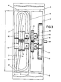
- the side walls 2, 6 form in connection with sections 4 ', 5' of the narrow walls 4 and 5, respectively, have a storage space which is rectangular in cross section and designed as a shaft 7. From Fig. 3 it can be seen that the length A of the shaft 7 is a multiple of the width B of the shaft, namely a ratio of 4: 1 is selected in the embodiment.
- rollers 10, 11 are seated on the shaft sections extending in the shaft opening in a rotationally fixed manner.
- annular grooves 12 are incorporated in the thickened collar in such a way that the rollers 10, 11 form a circular passage cross section for a cable 13.
- the passage cross section formed by the rollers is slightly smaller than the diameter of the cable 13, so that it is clamped frictionally between the rollers 10, 11.
- the rotary drive for the rollers is accommodated between the side walls 3, 6.
- this has a hand crank 16, the crank axis 16 'of which is mounted in the side walls 3, 6 and carries an externally toothed pulley 17 which extends between the side walls 3, 6.
- a screw 18 connects the pulley 17 in a rotationally fixed manner to the crank axis 16 '.
- a toothed belt 19 is placed around the pulley 17 and in turn drives a belt wheel 21 which is arranged on the shaft 9 in a rotationally fixed manner by means of a pin 20.
- a spur gear 22 sits in a rotationally fixed manner on the shaft 9, which meshes with a gear 23 fixed on the other shaft 8.
- roller 10 could be cushioned in the direction of the other roller 11 in order to vary the frictional connection between the cable 13 and the rollers.
- the hand crank 16 is to be turned clockwise.
- the pulley 17 that makes this rotation drives the pulley 21 via the toothed belt 19.
- the shaft 9 rotates with the roller 11 and the gearwheel 22 attached to it.
- the latter drives the other shaft 8 and the roller 10 seated thereon via the gearwheel 23, so that the cable 13 clamped frictionally by the rollers 10, 11 in the storeroom is pushed into it.
- the narrow shaft walls 4 'force the deflected cable 13 to be deflected, thereby achieving a loop-like self-laying, as is illustrated in FIGS. 1 and 3. Since the loop sections lie unevenly with respect to one another, the risk of heating by induction at high power connection values and with only partial cable removal is avoided.
- crank axis 16 ' an externally controlled shaft could also be provided, which, when such a device is arranged on a vacuum cleaner, is rotated by the vacuum cleaner motor, with the interposition of a clutch.
Landscapes
- Engineering & Computer Science (AREA)
- Mechanical Engineering (AREA)
- Signal Processing (AREA)
- Storing, Repeated Paying-Out, And Re-Storing Of Elongated Articles (AREA)
- Electrical Discharge Machining, Electrochemical Machining, And Combined Machining (AREA)
- Superconductors And Manufacturing Methods Therefor (AREA)
- Automatic Disk Changers (AREA)
- Extrusion Moulding Of Plastics Or The Like (AREA)
- Details Of Indoor Wiring (AREA)
- Communication Cables (AREA)
- Luminescent Compositions (AREA)
- Spectrometry And Color Measurement (AREA)
- Liquid Crystal Substances (AREA)
Priority Applications (1)
| Application Number | Priority Date | Filing Date | Title |
|---|---|---|---|
| AT82101223T ATE8840T1 (de) | 1981-04-04 | 1982-02-18 | Vorrichtung zum speichern von elektrokabeln. |
Applications Claiming Priority (2)
| Application Number | Priority Date | Filing Date | Title |
|---|---|---|---|
| DE8110209U | 1981-04-04 | ||
| DE8110209U DE8110209U1 (de) | 1981-04-04 | 1981-04-04 | Vorrichtung zum Speichern von Elektrokabeln, insbesondere an Staubsaugern |
Publications (2)
| Publication Number | Publication Date |
|---|---|
| EP0063217A1 true EP0063217A1 (fr) | 1982-10-27 |
| EP0063217B1 EP0063217B1 (fr) | 1984-08-08 |
Family
ID=6726511
Family Applications (1)
| Application Number | Title | Priority Date | Filing Date |
|---|---|---|---|
| EP82101223A Expired EP0063217B1 (fr) | 1981-04-04 | 1982-02-18 | Dispositif pour emmagasiner des câbles électriques |
Country Status (7)
| Country | Link |
|---|---|
| EP (1) | EP0063217B1 (fr) |
| AT (1) | ATE8840T1 (fr) |
| DE (2) | DE8110209U1 (fr) |
| DK (1) | DK108382A (fr) |
| ES (1) | ES271933Y (fr) |
| FI (1) | FI70350C (fr) |
| NO (1) | NO154036C (fr) |
Cited By (10)
| Publication number | Priority date | Publication date | Assignee | Title |
|---|---|---|---|---|
| FR2624714A1 (fr) * | 1987-12-18 | 1989-06-23 | Bosch Siemens Hausgeraete | Aspirateur manuel de poussieres, notamment de petit modele |
| EP0293205A3 (fr) * | 1987-05-27 | 1989-12-13 | Robert Stewart Knight | Amplificateur pour système d'annonce en public |
| EP1138238A1 (fr) * | 2000-03-31 | 2001-10-04 | BSH Bosch und Siemens Hausgeräte GmbH | Dispositif de rangement du câble d'un appareil domestique |
| FR2824196A1 (fr) * | 2001-04-27 | 2002-10-31 | Heli 33 Soc D Expl Des Etablis | Dispositif de stockage d'un cable electique formant une rallonge |
| WO2003001960A1 (fr) | 2001-06-29 | 2003-01-09 | BSH Bosch und Siemens Hausgeräte GmbH | Dispositif pour enrouler un cable |
| WO2006008249A1 (fr) * | 2004-07-22 | 2006-01-26 | BSH Bosch und Siemens Hausgeräte GmbH | Element boitier pour appareil electromenager |
| WO2007017321A1 (fr) * | 2005-08-08 | 2007-02-15 | BSH Bosch und Siemens Hausgeräte GmbH | Appareil electrique dote d'un logement pour cable |
| CN110950184A (zh) * | 2019-10-31 | 2020-04-03 | 惠而浦(中国)股份有限公司 | 家用电器的胶轮集线装置 |
| US11166773B2 (en) | 2016-09-09 | 2021-11-09 | Intuitive Surgical Operations, Inc. | Stapler beam architecture |
| US20250136405A1 (en) * | 2023-11-01 | 2025-05-01 | Lockheed Martin Corporation | Cable management drive system for industrial robots |
Families Citing this family (1)
| Publication number | Priority date | Publication date | Assignee | Title |
|---|---|---|---|---|
| DE102011090207A1 (de) | 2011-12-30 | 2013-07-04 | Dr. Ing. H.C. F. Porsche Ag | Bevorratungsvorrichtung |
Citations (5)
| Publication number | Priority date | Publication date | Assignee | Title |
|---|---|---|---|---|
| NL57858C (fr) * | 1900-01-01 | |||
| FR789378A (fr) * | 1935-04-30 | 1935-10-28 | Dispositif d'enroulement pour fil de téléphone et autres appareils | |
| DE653166C (de) * | 1935-11-02 | 1937-11-16 | Walter Kuhn | Selbsttaetige Kabelaufwickelvorrichtung fuer Staubsauger |
| FR2325593A1 (fr) * | 1975-09-29 | 1977-04-22 | Philips Nv | Dispositif de freinage destine a un tambour de cable |
| EP0044490A2 (fr) * | 1980-07-17 | 1982-01-27 | Siemens Aktiengesellschaft | Dispositif électrique de nettoyage ayant un appareil d'enroulement de câble incorporé |
-
1981
- 1981-04-04 DE DE8110209U patent/DE8110209U1/de not_active Expired
-
1982
- 1982-01-25 FI FI820219A patent/FI70350C/fi not_active IP Right Cessation
- 1982-02-18 DE DE8282101223T patent/DE3260510D1/de not_active Expired
- 1982-02-18 AT AT82101223T patent/ATE8840T1/de not_active IP Right Cessation
- 1982-02-18 EP EP82101223A patent/EP0063217B1/fr not_active Expired
- 1982-02-19 ES ES1982271933U patent/ES271933Y/es not_active Expired
- 1982-03-12 DK DK108382A patent/DK108382A/da not_active Application Discontinuation
- 1982-04-02 NO NO821129A patent/NO154036C/no unknown
Patent Citations (5)
| Publication number | Priority date | Publication date | Assignee | Title |
|---|---|---|---|---|
| NL57858C (fr) * | 1900-01-01 | |||
| FR789378A (fr) * | 1935-04-30 | 1935-10-28 | Dispositif d'enroulement pour fil de téléphone et autres appareils | |
| DE653166C (de) * | 1935-11-02 | 1937-11-16 | Walter Kuhn | Selbsttaetige Kabelaufwickelvorrichtung fuer Staubsauger |
| FR2325593A1 (fr) * | 1975-09-29 | 1977-04-22 | Philips Nv | Dispositif de freinage destine a un tambour de cable |
| EP0044490A2 (fr) * | 1980-07-17 | 1982-01-27 | Siemens Aktiengesellschaft | Dispositif électrique de nettoyage ayant un appareil d'enroulement de câble incorporé |
Cited By (12)
| Publication number | Priority date | Publication date | Assignee | Title |
|---|---|---|---|---|
| EP0293205A3 (fr) * | 1987-05-27 | 1989-12-13 | Robert Stewart Knight | Amplificateur pour système d'annonce en public |
| FR2624714A1 (fr) * | 1987-12-18 | 1989-06-23 | Bosch Siemens Hausgeraete | Aspirateur manuel de poussieres, notamment de petit modele |
| EP1138238A1 (fr) * | 2000-03-31 | 2001-10-04 | BSH Bosch und Siemens Hausgeräte GmbH | Dispositif de rangement du câble d'un appareil domestique |
| FR2824196A1 (fr) * | 2001-04-27 | 2002-10-31 | Heli 33 Soc D Expl Des Etablis | Dispositif de stockage d'un cable electique formant une rallonge |
| WO2003001960A1 (fr) | 2001-06-29 | 2003-01-09 | BSH Bosch und Siemens Hausgeräte GmbH | Dispositif pour enrouler un cable |
| US7108217B2 (en) | 2001-06-29 | 2006-09-19 | BSH Bosch und Siemens Hausgeräte GmbH | Device for storing a cable |
| WO2006008249A1 (fr) * | 2004-07-22 | 2006-01-26 | BSH Bosch und Siemens Hausgeräte GmbH | Element boitier pour appareil electromenager |
| WO2007017321A1 (fr) * | 2005-08-08 | 2007-02-15 | BSH Bosch und Siemens Hausgeräte GmbH | Appareil electrique dote d'un logement pour cable |
| US11166773B2 (en) | 2016-09-09 | 2021-11-09 | Intuitive Surgical Operations, Inc. | Stapler beam architecture |
| US12102401B2 (en) | 2016-09-09 | 2024-10-01 | Intuitive Surgical Operations, Inc. | Stapler beam architecture |
| CN110950184A (zh) * | 2019-10-31 | 2020-04-03 | 惠而浦(中国)股份有限公司 | 家用电器的胶轮集线装置 |
| US20250136405A1 (en) * | 2023-11-01 | 2025-05-01 | Lockheed Martin Corporation | Cable management drive system for industrial robots |
Also Published As
| Publication number | Publication date |
|---|---|
| ES271933Y (es) | 1984-07-01 |
| NO154036C (no) | 1986-07-09 |
| FI820219L (fi) | 1982-10-05 |
| NO154036B (no) | 1986-04-01 |
| FI70350B (fi) | 1986-02-28 |
| NO821129L (no) | 1982-10-05 |
| DE3260510D1 (en) | 1984-09-13 |
| EP0063217B1 (fr) | 1984-08-08 |
| ES271933U (es) | 1983-12-16 |
| ATE8840T1 (de) | 1984-08-15 |
| DE8110209U1 (de) | 1981-12-03 |
| FI70350C (fi) | 1986-09-15 |
| DK108382A (da) | 1982-10-05 |
Similar Documents
| Publication | Publication Date | Title |
|---|---|---|
| DE2749137C2 (fr) | ||
| DE3418052A1 (de) | Elektrisch angetriebene pressvorrichtung fuer die druckbeaufschlagung einer viskosen masse | |
| EP0063217A1 (fr) | Dispositif pour emmagasiner des câbles électriques | |
| DE2639000A1 (de) | Mechanisches mehrganggetriebe fuer fahrzeuge | |
| DE60008438T2 (de) | Zitrus-fruchtpresse mit schleudern des gepresseten produkts | |
| EP0098482B1 (fr) | Dispositif de levage ou de dépose pour des réceptacles transportables, par exemple conteneurs, abris, structures amovibles ou semblables | |
| DE2643177B2 (de) | Zahnraederwechselgetriebe | |
| DE19624857B4 (de) | Kurzbauendes Sechsganggetriebe | |
| DE4110665A1 (de) | Hebezeug | |
| EP1039825A1 (fr) | Systeme de transmission | |
| DE10004698A1 (de) | Handbandschleifer | |
| CH546615A (de) | Elektrowerkzeug mit einem zweigang-getriebe. | |
| DE10016331A1 (de) | Küchenmaschine | |
| DE2129771A1 (de) | Elektrowerkzeug mit Zweigang-Getriebe | |
| DE3230648C2 (de) | Winkelwendegetriebe | |
| DE1113621B (de) | Umlaufraedergetriebe mit Leistungsverzweigung in mechanische und hydrostatische Zweige | |
| DE19510562A1 (de) | Rütteleinrichtung | |
| DE2622474C2 (de) | Zahnräderwechselgetriebe, insbesondere für landwirtschaftlich nutzbare Fahrzeuge | |
| DE945826C (de) | Doppeltrommelantrieb fuer Foerderbaender od. dgl. | |
| DE3028833C2 (fr) | ||
| DE903658C (de) | Aussenantriebseinrichtung an einem Geschwindigkeitswechselgetriebe fuer Kraftfahrzeuge | |
| DE519216C (de) | Umlaufraedergetriebe, insbesondere fuer Kraftfahrzeuge | |
| DE2927768A1 (de) | Mechanisches schaltwerkgetriebe zur stufenlosen drehzahlregelung | |
| DE725827C (de) | Zweimotorenantrieb fuer Winden | |
| DE2409976A1 (de) | Schaltgestaenge, insbesondere zum schalten des rueckwaertsganges oder des nebenantriebs von kraftfahrzeuggetrieben |
Legal Events
| Date | Code | Title | Description |
|---|---|---|---|
| PUAI | Public reference made under article 153(3) epc to a published international application that has entered the european phase |
Free format text: ORIGINAL CODE: 0009012 |
|
| AK | Designated contracting states |
Designated state(s): AT CH DE FR GB IT SE |
|
| 17P | Request for examination filed |
Effective date: 19830114 |
|
| ITF | It: translation for a ep patent filed | ||
| GRAA | (expected) grant |
Free format text: ORIGINAL CODE: 0009210 |
|
| AK | Designated contracting states |
Designated state(s): AT CH DE FR GB IT LI SE |
|
| REF | Corresponds to: |
Ref document number: 8840 Country of ref document: AT Date of ref document: 19840815 Kind code of ref document: T |
|
| REF | Corresponds to: |
Ref document number: 3260510 Country of ref document: DE Date of ref document: 19840913 |
|
| ET | Fr: translation filed | ||
| PLBE | No opposition filed within time limit |
Free format text: ORIGINAL CODE: 0009261 |
|
| STAA | Information on the status of an ep patent application or granted ep patent |
Free format text: STATUS: NO OPPOSITION FILED WITHIN TIME LIMIT |
|
| 26N | No opposition filed | ||
| ITTA | It: last paid annual fee | ||
| EAL | Se: european patent in force in sweden |
Ref document number: 82101223.4 |
|
| PGFP | Annual fee paid to national office [announced via postgrant information from national office to epo] |
Ref country code: CH Payment date: 19970120 Year of fee payment: 16 Ref country code: AT Payment date: 19970120 Year of fee payment: 16 |
|
| PGFP | Annual fee paid to national office [announced via postgrant information from national office to epo] |
Ref country code: GB Payment date: 19970210 Year of fee payment: 16 Ref country code: DE Payment date: 19970210 Year of fee payment: 16 |
|
| PGFP | Annual fee paid to national office [announced via postgrant information from national office to epo] |
Ref country code: SE Payment date: 19970217 Year of fee payment: 16 |
|
| PGFP | Annual fee paid to national office [announced via postgrant information from national office to epo] |
Ref country code: FR Payment date: 19970228 Year of fee payment: 16 |
|
| PG25 | Lapsed in a contracting state [announced via postgrant information from national office to epo] |
Ref country code: GB Free format text: LAPSE BECAUSE OF NON-PAYMENT OF DUE FEES Effective date: 19980218 Ref country code: AT Free format text: LAPSE BECAUSE OF NON-PAYMENT OF DUE FEES Effective date: 19980218 |
|
| PG25 | Lapsed in a contracting state [announced via postgrant information from national office to epo] |
Ref country code: SE Free format text: LAPSE BECAUSE OF NON-PAYMENT OF DUE FEES Effective date: 19980219 |
|
| PG25 | Lapsed in a contracting state [announced via postgrant information from national office to epo] |
Ref country code: LI Free format text: LAPSE BECAUSE OF NON-PAYMENT OF DUE FEES Effective date: 19980228 Ref country code: FR Free format text: THE PATENT HAS BEEN ANNULLED BY A DECISION OF A NATIONAL AUTHORITY Effective date: 19980228 Ref country code: CH Free format text: LAPSE BECAUSE OF NON-PAYMENT OF DUE FEES Effective date: 19980228 |
|
| GBPC | Gb: european patent ceased through non-payment of renewal fee |
Effective date: 19980218 |
|
| REG | Reference to a national code |
Ref country code: CH Ref legal event code: PL |
|
| EUG | Se: european patent has lapsed |
Ref document number: 82101223.4 |
|
| PG25 | Lapsed in a contracting state [announced via postgrant information from national office to epo] |
Ref country code: DE Free format text: LAPSE BECAUSE OF NON-PAYMENT OF DUE FEES Effective date: 19981103 |
|
| REG | Reference to a national code |
Ref country code: FR Ref legal event code: ST |