EP0063218A2 - Tile with ventilating gap - Google Patents
Tile with ventilating gap Download PDFInfo
- Publication number
- EP0063218A2 EP0063218A2 EP82101313A EP82101313A EP0063218A2 EP 0063218 A2 EP0063218 A2 EP 0063218A2 EP 82101313 A EP82101313 A EP 82101313A EP 82101313 A EP82101313 A EP 82101313A EP 0063218 A2 EP0063218 A2 EP 0063218A2
- Authority
- EP
- European Patent Office
- Prior art keywords
- roof tile
- cover
- collar
- edge
- inner surfaces
- Prior art date
- Legal status (The legal status is an assumption and is not a legal conclusion. Google has not performed a legal analysis and makes no representation as to the accuracy of the status listed.)
- Granted
Links
- 238000009423 ventilation Methods 0.000 claims abstract description 12
- 210000002105 tongue Anatomy 0.000 claims description 10
- 238000011161 development Methods 0.000 description 2
- 230000018109 developmental process Effects 0.000 description 2
- 238000005452 bending Methods 0.000 description 1
- 238000003780 insertion Methods 0.000 description 1
- 230000037431 insertion Effects 0.000 description 1
- 238000001556 precipitation Methods 0.000 description 1
- 230000036316 preload Effects 0.000 description 1
- 238000007493 shaping process Methods 0.000 description 1
- 230000006641 stabilisation Effects 0.000 description 1
- 238000011105 stabilization Methods 0.000 description 1
Images


Classifications
-
- E—FIXED CONSTRUCTIONS
- E04—BUILDING
- E04D—ROOF COVERINGS; SKY-LIGHTS; GUTTERS; ROOF-WORKING TOOLS
- E04D1/00—Roof covering by making use of tiles, slates, shingles, or other small roofing elements
- E04D1/30—Special roof-covering elements, e.g. ridge tiles, gutter tiles, gable tiles, ventilation tiles
-
- E—FIXED CONSTRUCTIONS
- E04—BUILDING
- E04D—ROOF COVERINGS; SKY-LIGHTS; GUTTERS; ROOF-WORKING TOOLS
- E04D1/00—Roof covering by making use of tiles, slates, shingles, or other small roofing elements
- E04D1/29—Means for connecting or fastening adjacent roofing elements
- E04D1/2907—Means for connecting or fastening adjacent roofing elements by interfitted sections
- E04D1/2914—Means for connecting or fastening adjacent roofing elements by interfitted sections having fastening means or anchors at juncture of adjacent roofing elements
- E04D1/2916—Means for connecting or fastening adjacent roofing elements by interfitted sections having fastening means or anchors at juncture of adjacent roofing elements the fastening means taking hold directly on adjacent elements of the same row
-
- E—FIXED CONSTRUCTIONS
- E04—BUILDING
- E04D—ROOF COVERINGS; SKY-LIGHTS; GUTTERS; ROOF-WORKING TOOLS
- E04D1/00—Roof covering by making use of tiles, slates, shingles, or other small roofing elements
- E04D1/30—Special roof-covering elements, e.g. ridge tiles, gutter tiles, gable tiles, ventilation tiles
- E04D2001/309—Ventilation tiles
Definitions
- the invention relates to a roof tile with a raised central region in the transverse direction and a ventilation opening arranged there, from the edge of which an upward-facing collar emerges, which is covered by a cover with a downward-facing edge strip while leaving an air passage slot.
- a hood of this type is known from DE-PS 22 57 885. It is designed as a sliding hood and can be brought into an open or closed position by shifting in the direction of inclination.
- the cover is extended in the direction mentioned and divided by a strip-like closure part running inside the hood and extending transversely to the eaves. This closure part and one of the two eaves parallel edge strips are in the closure system on the corresponding collar sections. The necessity of the adjustment is perceived as annoying. Slipping snow can cause the cover to move unnoticed.
- there is a risk of driving rain since the impact distance to the top edge of the collar, which runs at a level, is different due to the mostly undulating roof tile structure.
- the object of the invention is to provide a generic roof tile, in which the ventilation function is uninterrupted, but on the other hand the entry of moisture is excluded to a high degree.
- the air passage slot is adapted to the curvature of the roof tile, i.e. the upward-facing collar that determines the lower edge of the ventilation slot ends at the same height distance from the top of the roof tile that forms the impact surface.
- the upper edges of both transverse collar sections and the inner surfaces of the cover hood have curved lines corresponding to the transverse curvature. The contour adjustment can be carried out so far that the upper edges and the inner surfaces even run parallel to one another.
- Corresponding connecting means can be taken into account when shaping the roof tile or cover hood and bring additional stabilization of the collar sections which are kept as thin-walled as possible.
- the upper edge of the ridge-side collar section runs parallel to the inner surface of the cover and the upper edge of the eaves-side collar section with an intermediate Section tangential to the downward curvature line of the cover. This advance of an intermediate section brings on the one hand only an insignificant change in the air passage slot, but on the other hand an additional support zone.
- the roof tile has a ventilation opening 1 in its raised, arched central area M.
- the latter is of rectangular plan. The longer edges of the opening extend in the direction of the roof tile inclination.
- the ventilation opening 1 is delimited by an upwardly directed collar K.
- the cover 4 which is also rectangular in shape, merges into an all-round, downward-facing edge strip 5. Edge strip 5 and collar K overlap one another (see FIG. 7), so that the ventilation flow takes a Z-shaped course 6 in the region of the air passage slot 3.
- the gap width y between the edge strip 5 and the collar K corresponds approximately to the gap width z between the 'upper edge 2' and the inner surfaces 4 'of the cover 4.
- the ridge-side section 5 'of the edge strip 5 extends to the top wide surface B of the roof tile.
- the lower edge of the skirting board 5 "there is adapted to the curvature of the roof tiles.
- the relevant section is somewhat exposed on the ridge side.
- the deep-drawn section 5 'of the skirting board forms an apron so that rainwater is drained off. There is consequently no direct air inlet or drainage . emerges; rather, this occurs from the long sides.
- Clamping tongues 7 are used to fasten the cover 4 to the roof tile.
- the latter can also be integrally formed on the inside of the cover 4.
- the plug-in channel 9 of the guide shoes 8 is perpendicular to the pan plane. As can be seen from FIG. 10, the plug-in channels left open to the ventilation opening 1 are undercut like a dovetail. The undercuts are labeled 9 '.
- the clamping tongues have a transverse curvature. The crown of the bulge is on the collar section side. Due to a certain bending elasticity in connection with a certain preload, high clamping forces can be applied between the clamping tongue and the guide shoe.
- the insertion limitation of the roof tongue-side clamping tongue 7 is formed by the edge strip section which strikes the upper broad area B.
- the entry of the clamping tongue on the eaves side is limited by the guide shoe itself, in that the plug-in channel 9 is closed on the bottom side.
- the stopper-forming material web extending from undercut to undercut there is designated by 10.
- the removability of the cover 4 facilitates the removal of leaves that have got into the air passage slot 3.
Landscapes
- Engineering & Computer Science (AREA)
- Architecture (AREA)
- Civil Engineering (AREA)
- Structural Engineering (AREA)
- Roof Covering Using Slabs Or Stiff Sheets (AREA)
- Finishing Walls (AREA)
- Road Paving Structures (AREA)
- Building Environments (AREA)
Abstract
Die Erfindung hat eine Dachpfanne zum Gegenstand, deren in Querrichtung erhaben gewölbter Mittelbereich (M) eine Lüftungsöffnung (1) aufweist. Von deren Rand geht ein aufwärts gerichteter Kragen (K) aus. Letzterer endet in einem solchen Abstand unterhalb einer die Lüftungsöffnung (1) überfangenden Abdeckhaube, daß ein Luftdurchtrittsschlitz (3) verbleibt. Die Abdeckhaube bildet allseitig eine abwärts gerichtete Randleiste (5) aus. Die Zuordnung von Abdeckhaube und Kragen ist dergestalt, daß die Oberkanten (2') beider in Querrichtung verlaufender Kragenabschnitte (2) und die Innenflächen (4') der Abdeckhaube (4) entsprechend der Querwölbung verlaufende Bogenlinien besitzen. Der Luftdurchtrittsschlitz (3) ist so der Wölbungsstruktur der Dachpfanne angepaßt. Bei guter Lüftungsfunktion ergibt sich trotzdem ein hoher Schutz vor Feuchtigkeitseintritt.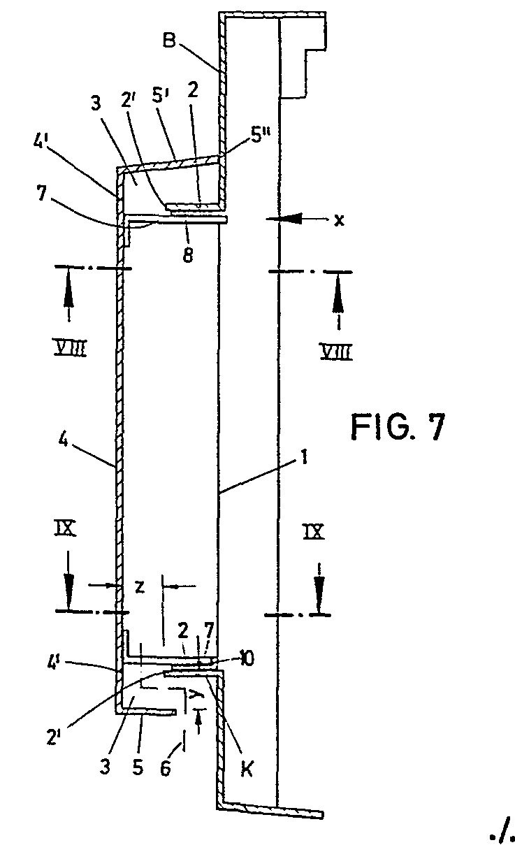

Description
Die Erfindung betrifft eine Dachpfanne mit in Querrichtung erhaben gewölbtem Mittelbereich und dort angeordneter Lüftungsöffnung, von deren Rand ein aufwärts gerichteter Kragen ausgeht, der unter Belassung eines Luftdurchtrittsschlitzes von einer Abdeckhaube mit abwärts gerichteter Randleiste überfangen ist.The invention relates to a roof tile with a raised central region in the transverse direction and a ventilation opening arranged there, from the edge of which an upward-facing collar emerges, which is covered by a cover with a downward-facing edge strip while leaving an air passage slot.
Eine Haube dieser Art ist durch die DE-PS 22 57 885 bekannt. Sie ist als Schiebehaube gestaltet und läßt sich durch Verlagerung in der Neigungsrichtung in eine Offen- oder Schließstellung bringen. Dazu ist die Abdeckhaube in der genannten Richtung verlängert und durch ein quer zur Traufe verlaufendes haubeninnenseitiges, leistenartiges Verschlußteil abgeteilt. Dieses Verschlußteil und eine der beiden traufenparallelen Randleisten sind in Verschlußanlage an den korrespondierenden Kragenabschnitten. Die Notwendigkeit der Verstellung wird als lästig empfunden. Abrutschender Schnee kann unbemerkt zu einer Verlagerung der Abdeckhaube führen. Überdies besteht die Gefahr des Eintritts von Schlagregen, da der Prallabstand zur auf einer Höhenebene verlaufenden Kragen-Oberkante zufolge der meist wellenförmigen Dachpfannenstruktur unterschiedlich ist.A hood of this type is known from DE-PS 22 57 885. It is designed as a sliding hood and can be brought into an open or closed position by shifting in the direction of inclination. For this purpose, the cover is extended in the direction mentioned and divided by a strip-like closure part running inside the hood and extending transversely to the eaves. This closure part and one of the two eaves parallel edge strips are in the closure system on the corresponding collar sections. The necessity of the adjustment is perceived as annoying. Slipping snow can cause the cover to move unnoticed. In addition, there is a risk of driving rain, since the impact distance to the top edge of the collar, which runs at a level, is different due to the mostly undulating roof tile structure.
Aufgabe der Erfindung ist es, eine gattungsgemäße Dachpfanne zu schaffen, bei der die Lüftungsfunktion unterbrechungsfrei gegeben ist, andererseits aber trotzdem der Eintritt von Feuchtigkeit in hohem Maße ausgeschlossen ist.The object of the invention is to provide a generic roof tile, in which the ventilation function is uninterrupted, but on the other hand the entry of moisture is excluded to a high degree.
Gelöst ist diese Aufgabe durch die im Anspruch 1 angegebene Erfindung.This object is achieved by the invention specified in
Die Unteransprüche sind vorteilhafte Weiterbildungen der Dachpfanne.The subclaims are advantageous developments of the roof tile.
Zufolge solcher Ausgestaltung ist eine gattungsgemäße Dachpfanne von insbesondere erhöhtem Gebrauchswert geschaffen: Der Luftdurchtrittsschlitz ist der Wölbungsstruktur der Dachpfanne angepaßt, d. h. der die Lüftungsschlitz-Unterkante bestimmende, aufwärts gerichtete Kragen endet überall im gleichen Höhenabstand zur die Prallfläche bildenden Oberseite der Dachpfanne. Die Oberkanten beider in Querrichtung verlaufender Kragenabschnitte und die Innenflächen der Abdeckhaube besitzen entsprechend der Querwölbung verlaufende Bogenlinien. Die Konturenanpassung läßt sich so weit führen, daß die Oberkanten und die Innenflächen sogar parallel zueinander verlaufen. In Gebieten, in denen hohe Niederschlagsraten üblich sind, kann bezüglich der firstseitigen Randleiste eine Weiterbildung dahingehend vorgenommen sein, daß die Abdeckhaube dort bis auf die Breitfläche der Dachpfanne reicht und dem dortigen Verlauf formschlüssig angepaßt ist. Das herabströmende Regenwasser prallt gegen diese schurzartig tiefergezogene Randleiste und verhindert so wirksam das etwa anzunehmende Hochschwappen über den öffnungsbildenden Kragen. Die entsprechende Ausgestaltung führt auch zu einer relativ großflächigen Abstützung der Haube in diesem Bereich. Ihre Festlegung geschieht unter Zuhilfenahme von Klemmzungen. Letztere treten in Führungsschuhe an den Innenflächen der in Querrichtung verlaufenden Kragenabschnitte ein, wobei der Eintritt in den traufenseitig liegenden Führungsschuh anschlagbegrenzt ist. Entsprechende Verbindungsmittel lassen sich beim Formen der Dachpfanne bzw. Abdeckhaube gleich mitberücksichtigen und bringen eine zusätzliche Stabilisierung der möglichst dünnwandig gehaltenen Kragenabschnitte. Schließlich besteht noch ein vorteilhaftes Merkmal darin, daß die Oberkante des firstseitigen Kragenabschnittes parallel verläuft zur Innenfläche der Abdeckhaube und die Oberkante des traufenseitigen Kragenabschnittes mit einem Zwischenabschnitt tangential liegt zur abwärts gerichteten Wölbungslinie der Abdeckhaube. Dieses Vorziehen eines Zwischenabschnittes bringt einerseits nur eine unbedeutende Veränderung des Luftdurchtrittsschlitzes, andererseits aber eine zusätzliche Stützzone.As a result of such a design, a generic roof tile of particularly high utility value is created: the air passage slot is adapted to the curvature of the roof tile, i.e. the upward-facing collar that determines the lower edge of the ventilation slot ends at the same height distance from the top of the roof tile that forms the impact surface. The upper edges of both transverse collar sections and the inner surfaces of the cover hood have curved lines corresponding to the transverse curvature. The contour adjustment can be carried out so far that the upper edges and the inner surfaces even run parallel to one another. In areas where high precipitation rates are common, a further development can be carried out with respect to the ridge-side edge strip in such a way that the covering hood extends there to the wide area of the roof tile and is adapted to the course there in a form-fitting manner. The downpouring rainwater bounces against this apron-like, lower rim and thus effectively prevents any sloshing over the opening-forming collar. The corresponding design also leads to a relatively large support of the hood in this area. They are determined with the aid of clamping tongues. The latter enter guide shoes on the inner surfaces of the collar sections running in the transverse direction, the entry into the guide shoe lying on the eaves side being limited by a stop. Corresponding connecting means can be taken into account when shaping the roof tile or cover hood and bring additional stabilization of the collar sections which are kept as thin-walled as possible. Finally, there is an advantageous feature that the upper edge of the ridge-side collar section runs parallel to the inner surface of the cover and the upper edge of the eaves-side collar section with an intermediate Section tangential to the downward curvature line of the cover. This advance of an intermediate section brings on the one hand only an insignificant change in the air passage slot, but on the other hand an additional support zone.
Weitere Vorteile und Einzelheiten des Gegenstandes der Erfindung sind nachstehend anhand eines zeichnerisch veranschaulichten Ausführungsbeispieles näher erläutert. Es zeigt:
- Fig. 1 die erfindungsgemäß ausgebildete Dachpfanne in Draufsicht,
- Fig. 2 eine Seitenansicht hierzu,
- Fig. 3 .die gegenüberliegende Seitenansicht,
- Fig. 4 die Unteransicht der Dachpfanne,
- Fig. 5 die Stirnansicht der Dachpfanne, und zwar von der Traufe aus gesehen,
- Fig. 6 die entsprechende Stirnansicht vom Dachfirst aus gesehen,
- Fig. 7 den Schnitt gemäß Linie VII-VII in Fig. 4, und zwar in gegenüber Fig. 4 vergrößertem Maßstab,
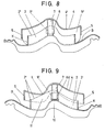
- Fig. 8 den Schnitt gemäß Linie VIII-VIII in Fig. 7,
- Fig. 9 den Schnitt gemäß Linie IX-IX in Fig. 7 und
- Fig. 10 das in Fig. 7 mit x bezeichnete Detail.
- 1 is a top view of the roof tile designed according to the invention,
- 2 is a side view of this,
- 3 the opposite side view,
- 4 the bottom view of the roof tile,
- 5 is an end view of the roof tile, seen from the eaves,
- 6 seen the corresponding end view from the ridge,
- 7 shows the section along line VII-VII in FIG. 4, namely on an enlarged scale compared to FIG. 4,
- 8 shows the section along line VIII-VIII in FIG. 7,
- Fig. 9 shows the section along line IX-IX in Fig. 7 and
- 10 shows the detail designated by x in FIG. 7.
Die Dachpfanne weist in ihrem erhaben gewölbten Mittelbereich M eine Lüftungsöffnung 1 auf. Letztere ist von rechteckigem Grundriß. Die längeren Öffnungsrandkanten erstrecken sich in der Dachpfannen-Neigungsrichtung.The roof tile has a ventilation opening 1 in its raised, arched central area M. The latter is of rectangular plan. The longer edges of the opening extend in the direction of the roof tile inclination.
Die Lüftungsöffnung 1 ist durch einen aufwärts gerichteten Kragen K begrenzt.The
Die Oberkante 2' beider in Querrichtung, d. h. parallel zur Traufe verlaufenden Kragenabschnitte 2 nehmen einen Verlauf, der dem des gewölbten Mittelbereichs M der Dachpfanne entspricht, ein. Unter Belassung eines allseitigen Luftdurchtrittsschlitzes 3 verlau- 'fen auch die darüber liegenden Innenflächen 4' einer die Lüftungsöffnung 1 schützend überfangenden Abdeckhaube 4. Die Bogenlinien der Innenflächen 4' können in ihren Querwölbungsmuster so gestaltet sein, daß die Oberkanten 2' der Kragenabschnitte 2 parallel zu den Innenflächen 4' verlaufen.The top edge 2 'of both in the transverse direction, i.e. H. Collar
Die ebenfalls rechteckig gestaltete Abdeckhaube 4 geht in eine umlaufend angeordnete, abwärts gerichtete Randleiste 5 über. Randleiste 5 und Kragen K überlappen einander (vergl. Fig. 7), so daß der Lüftungsstrom im Bereich des Luftdurchtrittsschlitzes 3 einen Z-förmigen Verlauf 6 nimmt.The
Die Spaltbreite y zwischen Randleiste 5 und Kragen K entspricht in etwa der Spaltbreite z zwischen 'Oberkante 2' und Innenflächen 4' der Abdeckhaube 4.The gap width y between the
Der firstseitige Abschnitt 5' der Randleiste 5 reicht bis auf die oberseitige Breitfläche B der Dachpfanne. Die Randleisten-Unterkante 5" ist dort dem Dachpfannen-Wölbungsverlauf angepaßt. Der diesbezügliche Abschnitt ist dachfirstseitig etwas ausgestellt. Der tiefgezogene Abschnitt 5' der Randleiste bildet einen Schurz, so daß abfließendes Regenwasser abgehalten wird. Von dorther besteht folglich auch kein direkter Luftein-bzw. austritt; dieser erfolgt vielmehr von den Längsseiten her.The ridge-side section 5 'of the
Zur Befestigung der Abdeckhaube 4 an der Dachpfanne dienen Klemmzungen 7. Letztere können der Abdeckhaube 4 innenseitig gleich mit angeformt sein. Es sind zwei in der Längsmitte liegende Klemmzungen 7 angebracht. Diese treten in Führungsschuhe 8 ein. Letztere liegen an den Innenflächen der in Querrichtung, also parallel zur Traufe verlaufenden Kragenabschnitte 2. Der Steckkanal 9 der Führungsschuhe 8 liegt senkrecht zur Pfannenebene. Wie aus Fig. 10 ersichtlich, sind die zur Lüftungsöffnung 1 hin offengelassenen Steckkanäle schwalbenschwanzartig hinterschnitten. Die Hinterschneidungen sind mit 9' bezeichnet. Die Klemmzungen weisen eine Querwölbung auf. Der Wölbungsscheitel liegt kragenabschnittseitig. Aufgrund einer gewissen Biegeelastizität im Zusammenhang mit einer gewissen Vorspannung lassen sich hohe Klemmkräfte zwischen Klemmzunge und Führungsschuh aufbringen.Clamping
Die Einsteckbegrenzung der dachfirstseitigen Klemmzunge 7 wird vom gegen die obere Breitfläche B tretenden Randleisten-Abschnitt gebildet. Der Eintritt der traufenseitig liegenden Klemmzunge ist durch den Führungsschuh selbst anschlagbegrenzt, indem der Steckkanal 9 bodenseitig geschlossen ist. Der dort von Hinterschneidung zu Hinterschneidung reichende, anschlagbildende Materialsteg ist mit 10 bezeichnet.The insertion limitation of the roof tongue-
Zufolge der Tatsache, daß die firstseitige Randleisten-Unterkante 5" auf ganzer Länge auf der oberen Breitfläche B der Dachpfanne ruht, genügt es im allgemeinen, die traufenseitige, eher punktförmige Abstützung über die dortige Klemmzunge zu bewirken, zumal die lange Steckführung ein Kippen ausschließt. In Fällen, in denen Witterungseinflüsse wie Schnee oder dergleichen einen ernsthaften Faktor bilden, kann über diese klemmzungenseitige Abstützung hinaus aber noch ein weiterer Stützpunkt geschaffen werden. Während nämlich die Oberkante 2' des firstseitigen Kragenabschnittes 2 parallel zur Innenfläche 4' der Haube 4 verläuft, nimmt die Oberkante 2' des traufenseitigen Kragenabschnittes 2 einen diese Parallelität ein einer Stelle aufgebenden Verlauf. Der dortige Kragenabschnitt liegt nämlich mit einem Zwischenabschnitt 11 tangential zur abwärts gerichteten Wölbungslinie L der Abdeckhaube 4 an. Es wird auf Fig. 9 verwiesen. Wie erkennbar, liegt außer der Klemmzungenseitigen Abstützung dadurch ein zweiter, im Abstand seitlich dazu vorgesehener Abstützpunkt vor.Due to the fact that the ridge-side
Die Abnehmbarkeit der Abdeckhaube 4 erleichtert das Entfernen von in den Luftdurchtrittsschlitz 3 geratenen Laubes.The removability of the
Alle in der Beschreibung erwähnten und in der Zeichnung dargestellten neuen Merkmale sind erfindungswesentlich, auch soweit sie in den Ansprüchen nicht ausdrücklich beansprucht sind.All the new features mentioned in the description and shown in the drawing are essential to the invention, even if they are not expressly claimed in the claims.
Claims (5)
Priority Applications (1)
| Application Number | Priority Date | Filing Date | Title |
|---|---|---|---|
| AT82101313T ATE12964T1 (en) | 1981-04-18 | 1982-02-20 | ROOF TILE WITH VENTILATION OPENING. |
Applications Claiming Priority (2)
| Application Number | Priority Date | Filing Date | Title |
|---|---|---|---|
| DE8111861U | 1981-04-18 | ||
| DE19818111861U DE8111861U1 (en) | 1981-04-18 | 1981-04-18 | ROOF PANEL WITH VENTILATION |
Publications (3)
| Publication Number | Publication Date |
|---|---|
| EP0063218A2 true EP0063218A2 (en) | 1982-10-27 |
| EP0063218A3 EP0063218A3 (en) | 1983-07-20 |
| EP0063218B1 EP0063218B1 (en) | 1985-04-24 |
Family
ID=6726964
Family Applications (1)
| Application Number | Title | Priority Date | Filing Date |
|---|---|---|---|
| EP82101313A Expired EP0063218B1 (en) | 1981-04-18 | 1982-02-20 | Tile with ventilating gap |
Country Status (3)
| Country | Link |
|---|---|
| EP (1) | EP0063218B1 (en) |
| AT (1) | ATE12964T1 (en) |
| DE (2) | DE8111861U1 (en) |
Cited By (4)
| Publication number | Priority date | Publication date | Assignee | Title |
|---|---|---|---|---|
| GB2199860A (en) * | 1986-11-05 | 1988-07-20 | Glidevale Building Prod | Roof ventilation tile |
| FR2683571A1 (en) * | 1991-11-08 | 1993-05-14 | Goubaud Michel | Roof outlet incorporated into a roofing element, particularly for controlled mechanical ventilation |
| FR2698649A1 (en) * | 1992-10-01 | 1994-06-03 | Goubaud Michel | Roof ventilation outlet assembly fitting any roof - comprises baseplate with ventilation shaft through roof, with two louvred outlets on each side of shaft, and V=shaped cover, with outlets having protective grills |
| GB2290568A (en) * | 1994-06-25 | 1996-01-03 | Phi Design Ltd | Ventilation tile |
Families Citing this family (1)
| Publication number | Priority date | Publication date | Assignee | Title |
|---|---|---|---|---|
| DE8813238U1 (en) * | 1988-10-21 | 1990-02-22 | Klöber, Johannes, 5828 Ennepetal | Roof covering panel |
Family Cites Families (2)
| Publication number | Priority date | Publication date | Assignee | Title |
|---|---|---|---|---|
| GB1058903A (en) * | 1963-05-06 | 1967-02-15 | George Forrester Sutherland | Adjustable pivotal mounting means for covers |
| DE2257885C3 (en) * | 1972-11-25 | 1980-09-18 | Braas & Co Gmbh, 6000 Frankfurt | Roofing panel with a rectangular cutout for ventilation and lighting of the roof interior and with a movable cover hood |
-
1981
- 1981-04-18 DE DE19818111861U patent/DE8111861U1/en not_active Expired
-
1982
- 1982-02-20 EP EP82101313A patent/EP0063218B1/en not_active Expired
- 1982-02-20 AT AT82101313T patent/ATE12964T1/en not_active IP Right Cessation
- 1982-02-20 DE DE8282101313T patent/DE3263220D1/en not_active Expired
Cited By (6)
| Publication number | Priority date | Publication date | Assignee | Title |
|---|---|---|---|---|
| GB2199860A (en) * | 1986-11-05 | 1988-07-20 | Glidevale Building Prod | Roof ventilation tile |
| GB2199860B (en) * | 1986-11-05 | 1991-07-17 | Glidevale Building Prod | Roof ventilation tile |
| FR2683571A1 (en) * | 1991-11-08 | 1993-05-14 | Goubaud Michel | Roof outlet incorporated into a roofing element, particularly for controlled mechanical ventilation |
| FR2698649A1 (en) * | 1992-10-01 | 1994-06-03 | Goubaud Michel | Roof ventilation outlet assembly fitting any roof - comprises baseplate with ventilation shaft through roof, with two louvred outlets on each side of shaft, and V=shaped cover, with outlets having protective grills |
| GB2290568A (en) * | 1994-06-25 | 1996-01-03 | Phi Design Ltd | Ventilation tile |
| GB2290568B (en) * | 1994-06-25 | 1997-09-03 | Phi Design Ltd | A ventilated tile |
Also Published As
| Publication number | Publication date |
|---|---|
| ATE12964T1 (en) | 1985-05-15 |
| EP0063218B1 (en) | 1985-04-24 |
| DE3263220D1 (en) | 1985-05-30 |
| EP0063218A3 (en) | 1983-07-20 |
| DE8111861U1 (en) | 1981-09-24 |
Similar Documents
| Publication | Publication Date | Title |
|---|---|---|
| DE2846275A1 (en) | EDGE MOUNTING SYSTEM FOR PLANTED ROOFS | |
| EP1299603A1 (en) | Roof covering | |
| EP0063218B1 (en) | Tile with ventilating gap | |
| DE29919121U1 (en) | Roofing | |
| DE4016371C1 (en) | Ridge cover for building roof - has kite shaped cover shield which is wider than ridge slate at wider end | |
| DE4441296C1 (en) | Universal fan with pleated side parts in a sprayed version | |
| DE29608830U1 (en) | Ventilation element for roofs | |
| DE3813094C2 (en) | Fan ridge cap for rear ventilation of roofs | |
| DE973963C (en) | Ventilation device for roofs | |
| EP0761899B1 (en) | Roofing tile | |
| DE3301954C2 (en) | ||
| AT408363B (en) | Roofing tile | |
| DE69819326T2 (en) | Eaves brick | |
| EP1270841B1 (en) | Under ridge tile | |
| CH346993A (en) | Roof covering made entirely or partially of corrugated panels | |
| EP1001106B1 (en) | Ridge covering for ventilated roof | |
| DE2814707B2 (en) | ||
| EP0761898B1 (en) | Roofing tile | |
| DE2262924C3 (en) | Ridge cover | |
| DE2208771A1 (en) | VENTILATING FIRST SEAL | |
| AT377038B (en) | ROOF FAN FOR VENTILATING OR VENTILATION OF ROOFS | |
| DE20313027U1 (en) | Cover strip for ridge beams or rafters, is made from corrugated metal or alloy and has rows of ventilation holes | |
| DE2018948B2 (en) | Roof ventilator with subframe above duct in roof - accommodates heat expansion in transverse direction without material wrapping using slide surface | |
| EP0866192A2 (en) | Flat roofing tile | |
| WO2001036764A1 (en) | Ridge cover |
Legal Events
| Date | Code | Title | Description |
|---|---|---|---|
| PUAI | Public reference made under article 153(3) epc to a published international application that has entered the european phase |
Free format text: ORIGINAL CODE: 0009012 |
|
| AK | Designated contracting states |
Designated state(s): AT BE CH DE FR GB NL |
|
| 17P | Request for examination filed |
Effective date: 19821228 |
|
| PUAL | Search report despatched |
Free format text: ORIGINAL CODE: 0009013 |
|
| AK | Designated contracting states |
Designated state(s): AT BE CH DE FR GB LI NL |
|
| GRAA | (expected) grant |
Free format text: ORIGINAL CODE: 0009210 |
|
| AK | Designated contracting states |
Designated state(s): AT BE CH DE FR GB LI NL |
|
| REF | Corresponds to: |
Ref document number: 12964 Country of ref document: AT Date of ref document: 19850515 Kind code of ref document: T |
|
| REF | Corresponds to: |
Ref document number: 3263220 Country of ref document: DE Date of ref document: 19850530 |
|
| ET | Fr: translation filed | ||
| PLBE | No opposition filed within time limit |
Free format text: ORIGINAL CODE: 0009261 |
|
| STAA | Information on the status of an ep patent application or granted ep patent |
Free format text: STATUS: NO OPPOSITION FILED WITHIN TIME LIMIT |
|
| 26N | No opposition filed | ||
| PGFP | Annual fee paid to national office [announced via postgrant information from national office to epo] |
Ref country code: AT Payment date: 19870223 Year of fee payment: 6 |
|
| PG25 | Lapsed in a contracting state [announced via postgrant information from national office to epo] |
Ref country code: AT Effective date: 19880220 |
|
| PG25 | Lapsed in a contracting state [announced via postgrant information from national office to epo] |
Ref country code: LI Effective date: 19880229 Ref country code: CH Effective date: 19880229 |
|
| BERE | Be: lapsed |
Owner name: HANS KLOBER Effective date: 19880228 |
|
| REG | Reference to a national code |
Ref country code: CH Ref legal event code: PL |
|
| PGFP | Annual fee paid to national office [announced via postgrant information from national office to epo] |
Ref country code: FR Payment date: 19881230 Year of fee payment: 8 |
|
| PGFP | Annual fee paid to national office [announced via postgrant information from national office to epo] |
Ref country code: DE Payment date: 19890104 Year of fee payment: 8 |
|
| PG25 | Lapsed in a contracting state [announced via postgrant information from national office to epo] |
Ref country code: BE Effective date: 19890228 |
|
| PGFP | Annual fee paid to national office [announced via postgrant information from national office to epo] |
Ref country code: NL Payment date: 19890228 Year of fee payment: 8 Ref country code: GB Payment date: 19890228 Year of fee payment: 8 |
|
| PG25 | Lapsed in a contracting state [announced via postgrant information from national office to epo] |
Ref country code: GB Effective date: 19900220 |
|
| PG25 | Lapsed in a contracting state [announced via postgrant information from national office to epo] |
Ref country code: NL Effective date: 19900901 |
|
| NLV4 | Nl: lapsed or anulled due to non-payment of the annual fee | ||
| GBPC | Gb: european patent ceased through non-payment of renewal fee | ||
| PG25 | Lapsed in a contracting state [announced via postgrant information from national office to epo] |
Ref country code: FR Effective date: 19901031 |
|
| PG25 | Lapsed in a contracting state [announced via postgrant information from national office to epo] |
Ref country code: DE Effective date: 19901101 |
|
| REG | Reference to a national code |
Ref country code: FR Ref legal event code: ST |