EP0063246A2 - Procédé pour la mise en oeuvre d'un réacteur avec tube à oscillations pour des réactions chimiques - Google Patents
Procédé pour la mise en oeuvre d'un réacteur avec tube à oscillations pour des réactions chimiques Download PDFInfo
- Publication number
- EP0063246A2 EP0063246A2 EP82102310A EP82102310A EP0063246A2 EP 0063246 A2 EP0063246 A2 EP 0063246A2 EP 82102310 A EP82102310 A EP 82102310A EP 82102310 A EP82102310 A EP 82102310A EP 0063246 A2 EP0063246 A2 EP 0063246A2
- Authority
- EP
- European Patent Office
- Prior art keywords
- reactants
- reaction
- mixing section
- tube reactor
- vibrating tube
- Prior art date
- Legal status (The legal status is an assumption and is not a legal conclusion. Google has not performed a legal analysis and makes no representation as to the accuracy of the status listed.)
- Granted
Links
Images



Classifications
-
- F—MECHANICAL ENGINEERING; LIGHTING; HEATING; WEAPONS; BLASTING
- F23—COMBUSTION APPARATUS; COMBUSTION PROCESSES
- F23C—METHODS OR APPARATUS FOR COMBUSTION USING FLUID FUEL OR SOLID FUEL SUSPENDED IN A CARRIER GAS OR AIR
- F23C15/00—Apparatus in which combustion takes place in pulses influenced by acoustic resonance in a gas mass
-
- B—PERFORMING OPERATIONS; TRANSPORTING
- B01—PHYSICAL OR CHEMICAL PROCESSES OR APPARATUS IN GENERAL
- B01J—CHEMICAL OR PHYSICAL PROCESSES, e.g. CATALYSIS OR COLLOID CHEMISTRY; THEIR RELEVANT APPARATUS
- B01J3/00—Processes of utilising sub-atmospheric or super-atmospheric pressure to effect chemical or physical change of matter; Apparatus therefor
- B01J3/06—Processes using ultra-high pressure, e.g. for the formation of diamonds; Apparatus therefor, e.g. moulds or dies
- B01J3/08—Application of shock waves for chemical reactions or for modifying the crystal structure of substances
-
- C—CHEMISTRY; METALLURGY
- C01—INORGANIC CHEMISTRY
- C01B—NON-METALLIC ELEMENTS; COMPOUNDS THEREOF; METALLOIDS OR COMPOUNDS THEREOF NOT COVERED BY SUBCLASS C01C
- C01B3/00—Hydrogen; Gaseous mixtures containing hydrogen; Separation of hydrogen from mixtures containing it; Purification of hydrogen; Reversible storage of hydrogen
- C01B3/50—Separation of hydrogen or hydrogen-containing gases from gaseous mixtures, e.g. purification
-
- C—CHEMISTRY; METALLURGY
- C01—INORGANIC CHEMISTRY
- C01B—NON-METALLIC ELEMENTS; COMPOUNDS THEREOF; METALLOIDS OR COMPOUNDS THEREOF NOT COVERED BY SUBCLASS C01C
- C01B3/00—Hydrogen; Gaseous mixtures containing hydrogen; Separation of hydrogen from mixtures containing it; Purification of hydrogen; Reversible storage of hydrogen
- C01B3/50—Separation of hydrogen or hydrogen-containing gases from gaseous mixtures, e.g. purification
- C01B3/56—Separation of hydrogen or hydrogen-containing gases from gaseous mixtures, e.g. purification by contacting with solids; Regeneration of used solids
- C01B3/58—Separation of hydrogen or hydrogen-containing gases from gaseous mixtures, e.g. purification by contacting with solids; Regeneration of used solids including a catalytic reaction
Definitions
- the invention relates to a vibrating tube reactor according to the preamble of claim 1 and a method for operating such a reactor.
- the invention has for its object to provide a vibrating tube reactor of the type mentioned and a method for operating the same, with which it is possible to react with those reactants that are problematic with regard to mixing and feeding into the reaction chamber, such as e.g. B. tar and steam containing coal distillation gas, and its by-products.
- reactants that are problematic with regard to mixing and feeding into the reaction chamber, such as e.g. B. tar and steam containing coal distillation gas, and its by-products.
- the invention is achieved in terms of the vibrating tube reactor by the features of claim 1 and in terms of a method for operating such a vibrating tube reactor by the features of claim 10; Further developments of the invention result from the subclaims.
- Coal distillation gases are mixed at temperatures between 100 and 500 ° C, preferably between 150 and 400 ° C, with oxygen or gases containing oxygen.
- the cooling of the raw gases to the above temperatures is advantageously carried out using aqueous condensates which are part of the overall process possibly incurred.
- the intractable Koheldestillationsgasspaltung to synthesis gas in a resonant tube with a stoichiometric amount of oxygen is surprisingly possible, because in the pulsing process flow not only through ideal mixing processes high reaction g eschwindigkei- th be achieved, but also because a product gas with high carbon monoxide and hydrogen components from the Raw gas is created.
- the hydrogen and carbon monoxide components are first oxidized and the condensates and agglomerates of the raw gas escape the process more or less untreated.
- z. B. from a pulsating combustion (reaction) by one or more support flames, which can also be used for ignition.
- a gradually increasing, controllable mixing of the reactants in the mixing section is possible through the measures of claims 4 to 6. This ensures that the mixing ratio required for the reaction is only achieved shortly before entering the reaction chamber; unwanted early reactions can be avoided.
- Double vibrating tubes according to claim 8 allow an increase in the reaction quantities with the same Vibrating tube dimensions.
- Catalysts can be in the reaction chamber, but also in the resonance tube, e.g. B. in the form of wall coatings, mesh inserts or the like.
- reaction products in the vibrating tube reactor can also be subjected to a further chemical conversion, so that this reaction also takes place under the influence of the vibrations which promotes the reaction rate.
- this may be an act of CO and H 2 recovery from coal distillation gases by g eschal- preparing methanation.
- a vibrating tube reactor will not be on the reaction conditions before the start of the reaction - this applies above all to the temperature control. It is therefore advisable according to the invention to first set the reaction conditions with auxiliary reactants, these being selected so that the conditions of claim 10 are met with these auxiliary reactants even in the "cold" state of the reactor.
- Cooling condensates for gaseous reactants according to claim 12 can be condensed reactants and / or react tion products, but also other condensates from the process in which the method is used.
- a vibrating tube reactor such as. B. a plant for the pulsating partial oxidation of coal distillation gases, on structural individual elements from a mixing tube (mixing section) 1, a combustion chamber (reaction chamber) 2, a resonance tube 3 and a compensation chamber 4.
- Raw gas to be split (reactant) comes from above through a pipe socket 11 into the mixing tube 1.
- At the upper end of the mixing tube 1 there are two injector systems 9 and 10 for the supply of oxygen and / or air (reactant) in a housing 8 like a start gas.
- a start gas is recommended in some cases for heating up the system, for example before processing raw coke oven gases. It consists of a fuel gas, e.g. B.
- the gas streams mixing in the mixing tube 1 are conducted at a conveying speed above 13 m / s in order to avoid flame residues in the mixing tube 1.
- the gas mixed in the mixing tube 1 now enters the combustion chamber 2 in order to be ignited here. This takes place, at least in the start-up phase of the system, by means of the auxiliary burner 7a.
- the resonance tube 3 now works from the first ignition at a frequency which is known to be given by the length distance between the mixing tube outlet and the compensation chamber inlet. After the start-up phase, the auxiliary burner 7a can be extinguished since further ignitions inevitably occur.
- the support burner 7b is arranged in the compensation chamber 4, which can be secured with an explosion flap 6 for all cases.
- the product gas is discharged from a suction device 5 through a heat exchanger 15 for cooling and through two cleaning stages 16 and 17, provided that the reactants are not present at an excess pressure which is sufficiently high to monitor the flow resistances.
- the mixing tube 1 is shown as the most important part of the system in detail.
- two injector systems 9 and 10 are provided for the supply of air and / or oxygen and the starting gas (the latter optionally).
- Each injector system consists of an annular chamber 9a and 10a, which supplies the medium supplied to it via a narrow annular gap 9b and 10b obliquely and radially to the mixing tube 1 in such a way that the medium, for example the oxygen, continues to coat the surface of the mixing tube 1 for a while .
- the feed head 12 At the lower end of the mixing tubes 1 there is the feed head 12 for the premixed fuel components.
- the feed head 12 is provided with a cooling system (cooling device) 13.
- the mixing tube wall By coating the mixing tube wall with air and / or oxygen and cooling a tear-off edge 14 at the mouth of the mixing tube, it is possible to restrict unavoidable tar condensation in such a way that coke formation is avoided.
- the cooled tear-off edge 14 drains the condensate droplets running off the warm mixing tube wall into the combustion chamber 2.
- the mixing tube, the combustion chamber and the resonance tube are arranged vertically.
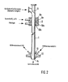
- a mixing tube is presented in which the reactants are partially mixed at different levels.
- a lance 18 is introduced into the mixing tube 1, which is provided over its length with openings 19 (slots or bores) from which the injected reactant can emerge.
- openings 19 slots or bores
- raw gases would be the injected reactant air and / or oxygen.
- the application largely prevents the flame front from kicking back into the mixing section if the system is operated under partial load and the required gas speeds in the mixing section are not achieved.
- Fig. 4 shows a vibrating tube circuit similar to the double vibrating tube from Esnault-Pelterie. In contrast to the arrangement shown, Esnault-Pelterie chose tuned resonance pipes in the compensation chamber.
- a Schwingrohrparr works in opposite directions on the principle of least constraint, d. that is, if the combustion chambers are equipped with pressure sensors, an oscillogram similar to 20 is obtained. It is therefore possible to operate in pairs several pipes connected to an equalization chamber.
- gas volumes are stated to be anhydrous under normal conditions (pressure / temperature).
- the mixing section had a length of 1.2 m and a diameter of 0.04 m, the combustion chamber with a resonance tube had a length of 3 m and an average diameter of 0.25 m; the cylindrical compensation chamber had a diameter of 0.5 m and, according to FIG. 1, a length of 1 m.
- a raw coke oven gas with the composition given in Example 1 and the same temperature and pressure conditions is fed to the combustion chamber 2 via the mixing tube 1.
- 1 000 g / m 3 of water-containing steam (such as evaporated cooler condensate) is fed to the mixing tube 1 via nozzle 11b.
- a combustion chamber temperature of 1,020 ° C is measured.
- the product gas composition has 52.8% by volume H 21 5.9% by volume N 2 , 19.0% by volume CO, 1.3% by volume CH 4 and 20.8% by volume CO 2 on.
- a rotary kiln works up pitch-bonded coal moldings into semi-coke moldings.
- the exhaust gas obtained in the indirect firing having a composition of 27 vol .-% H 2, 52 vol .-% CH 4 + C 2 H 6, 1 vol .-% 0 2, 4 vol .-% C n H m, 7 vol .-% CO, 4 vol .-% CO 2 , 5 vol .-% N 2 goes to the mixing tube 1 at a temperature of 370 ° C and is mixed with 60 m 3 of oxygen at 20 ° C. After this process, a mixing temperature of 190 ° C is reached.
- the ignitable gas is driven through the mixing tube 1 at 40 m / s, the tear-off edge 14 being cooled to 120 ° C. In the combustion chamber 2, a max. Reaction temperature of 1,450 ° C measured.
- the thus partially oxidized carbonization with a composi- initially g of 43 vol .-% H 2, 1 vol .-% CH 4, 3 vol .-% N 2, 38 vol .-% CO, 15 vol .-% CO 2 is fed to the heat exchanger 15 via a well-insulated apparatus and cooled in it to 150 ° C. and then moved into a storage unit via the suction device 5 for further processing.
- the system elements 2, 3 and 4 are operated with a negative pressure of 25 mbar.
Landscapes
- Chemical & Material Sciences (AREA)
- Engineering & Computer Science (AREA)
- Organic Chemistry (AREA)
- Combustion & Propulsion (AREA)
- Inorganic Chemistry (AREA)
- Chemical Kinetics & Catalysis (AREA)
- Crystallography & Structural Chemistry (AREA)
- Mechanical Engineering (AREA)
- General Engineering & Computer Science (AREA)
- Physical Or Chemical Processes And Apparatus (AREA)
- Industrial Gases (AREA)
- Devices And Processes Conducted In The Presence Of Fluids And Solid Particles (AREA)
- Organic Low-Molecular-Weight Compounds And Preparation Thereof (AREA)
- Hydrogen, Water And Hydrids (AREA)
Applications Claiming Priority (2)
| Application Number | Priority Date | Filing Date | Title |
|---|---|---|---|
| DE19813115391 DE3115391A1 (de) | 1981-04-16 | 1981-04-16 | "verfahren und vorrichtung zur herstellung von wasserstoff- und kohlenoxidreichen gasen aus rohen kohledestillationsgasen |
| DE3115391 | 1981-04-16 |
Publications (3)
| Publication Number | Publication Date |
|---|---|
| EP0063246A2 true EP0063246A2 (fr) | 1982-10-27 |
| EP0063246A3 EP0063246A3 (en) | 1983-04-27 |
| EP0063246B1 EP0063246B1 (fr) | 1985-05-29 |
Family
ID=6130270
Family Applications (1)
| Application Number | Title | Priority Date | Filing Date |
|---|---|---|---|
| EP82102310A Expired EP0063246B1 (fr) | 1981-04-16 | 1982-03-20 | Procédé pour la mise en oeuvre d'un réacteur avec tube à oscillations pour des réactions chimiques |
Country Status (8)
| Country | Link |
|---|---|
| EP (1) | EP0063246B1 (fr) |
| JP (1) | JPS57190648A (fr) |
| AU (1) | AU553863B2 (fr) |
| BR (1) | BR8202179A (fr) |
| CA (1) | CA1195482A (fr) |
| DE (2) | DE3115391A1 (fr) |
| ES (1) | ES511230A0 (fr) |
| ZA (1) | ZA822607B (fr) |
Cited By (1)
| Publication number | Priority date | Publication date | Assignee | Title |
|---|---|---|---|---|
| US5629744A (en) * | 1994-04-22 | 1997-05-13 | Sony Corporation | Active matrix display device and timing generator |
Families Citing this family (3)
| Publication number | Priority date | Publication date | Assignee | Title |
|---|---|---|---|---|
| US6774275B2 (en) * | 2001-08-21 | 2004-08-10 | Catalytic Distillation Technologies | Pulse flow reaction |
| US10065157B2 (en) * | 2012-10-26 | 2018-09-04 | Blue Cube Ip Llc | Mixer and processes incorporating the same |
| CN110841587B (zh) * | 2019-12-16 | 2024-09-13 | 山东豪迈机械制造有限公司 | 一种反应装置及反应设备 |
Family Cites Families (5)
| Publication number | Priority date | Publication date | Assignee | Title |
|---|---|---|---|---|
| DE1186974B (de) * | 1963-04-03 | 1965-02-11 | Bergwerksverband Gmbh | Verfahren zur Reinigung von Kohlendestillationsgasen unter Erzeugung eines an Kohlenoxyd und Wasserstoff reichen Brenngases |
| DE1470697A1 (de) * | 1964-10-27 | 1969-04-10 | Bergwerksverband Gmbh | Verfahren zur Reinigung von rohen Kohlendestillationsgasen unter Erzeugung eines an Kohlenoxyd,Wasserstoff und gegebenenfalls Stickstoff reichen Brenngases |
| US3620698A (en) * | 1968-12-26 | 1971-11-16 | Texaco Inc | Hydrogen and carbon monoxide from slurries of solid carboniferous fuels |
| DE2638348A1 (de) * | 1976-08-26 | 1978-07-13 | Didier Eng | Verfahren zur weiterverarbeitung von koksofengas |
| US4110359A (en) * | 1976-12-10 | 1978-08-29 | Texaco Development Corporation | Production of cleaned and purified synthesis gas and carbon monoxide |
-
1981
- 1981-04-16 DE DE19813115391 patent/DE3115391A1/de not_active Withdrawn
-
1982
- 1982-03-20 EP EP82102310A patent/EP0063246B1/fr not_active Expired
- 1982-03-20 DE DE8282102310T patent/DE3263857D1/de not_active Expired
- 1982-04-07 ES ES511230A patent/ES511230A0/es active Granted
- 1982-04-13 AU AU82552/82A patent/AU553863B2/en not_active Ceased
- 1982-04-15 CA CA000401030A patent/CA1195482A/fr not_active Expired
- 1982-04-15 BR BR8202179A patent/BR8202179A/pt unknown
- 1982-04-16 ZA ZA822607A patent/ZA822607B/xx unknown
- 1982-04-16 JP JP57064617A patent/JPS57190648A/ja active Granted
Non-Patent Citations (1)
| Title |
|---|
| G.W.F., GAS- UND WASSERFACH, GAS-ERDGAS, Band 120, Heft 12, 1979, Seiten 574-578, R. Oldenbourg Verlag GmbH, M}nchen, DE; D. GEORGE et al.: "Die Technik der partiellen Oxidation von Kokerei-Rohgas im Schwingrohr". * |
Cited By (1)
| Publication number | Priority date | Publication date | Assignee | Title |
|---|---|---|---|---|
| US5629744A (en) * | 1994-04-22 | 1997-05-13 | Sony Corporation | Active matrix display device and timing generator |
Also Published As
| Publication number | Publication date |
|---|---|
| ES8304029A1 (es) | 1983-02-16 |
| CA1195482A (fr) | 1985-10-22 |
| EP0063246A3 (en) | 1983-04-27 |
| JPS57190648A (en) | 1982-11-24 |
| EP0063246B1 (fr) | 1985-05-29 |
| DE3263857D1 (en) | 1985-07-04 |
| DE3115391A1 (de) | 1982-12-30 |
| JPH028771B2 (fr) | 1990-02-27 |
| ZA822607B (en) | 1983-03-30 |
| BR8202179A (pt) | 1983-03-29 |
| AU553863B2 (en) | 1986-07-31 |
| ES511230A0 (es) | 1983-02-16 |
| AU8255282A (en) | 1982-10-21 |
Similar Documents
| Publication | Publication Date | Title |
|---|---|---|
| DE1543122C3 (de) | Verfahren zur Herstellung von vorwiegend Acetylen und Äthylen enthaltenden ungesättigten Kohlenwasserstoffen | |
| DE112010005033B4 (de) | Verfahren zur Vermehrung von Koksofengas durch die Verwendung von Kohlendioxid | |
| EP0110093B1 (fr) | Dispositif d'obtention d'un produit gazeux contenant de l'hydrogène et de l'oxyde de carbone | |
| DE3329048A1 (de) | Verfahren zur thermischen crackung von schweroel | |
| US4447333A (en) | Process for the elimination of ammonia in coke plant waste waters | |
| DE3606108A1 (de) | Verfahren und einrichtung zur herstellung eines hauptsaechlich co + h(pfeil abwaerts)2(pfeil abwaerts) enthaltenden gases durch thermisches reformen von gasfoermigem kohlenwasserstoff | |
| DE1645864B2 (de) | Anlage zur erzeugung von olefinen durch thermische spaltung von kohlenwasserstoffen im wirbelfliessverfahren und verfahren zur erzeugung von olefinen unter verwendung dieser anlage | |
| EP0063246B1 (fr) | Procédé pour la mise en oeuvre d'un réacteur avec tube à oscillations pour des réactions chimiques | |
| EP1390316A1 (fr) | Installation et procede de production de clinker de ciment | |
| EP2892864B1 (fr) | Procédé de production d'acétylène et de gaz de synthèse | |
| EP2945904B1 (fr) | Procédé de production d'acétylène et de gaz de synthèse | |
| EP2861527B1 (fr) | Procédé de production d'acétylène et de gaz de synthèse | |
| EP1160307B1 (fr) | Procédé et installation pour le traitement thermique et pour la conversion chimique de matériaux naturels ou synthétiques en gaz | |
| DE2837416C3 (de) | Vorrichtung zur Weiterverarbeitung von Kohleentgasungsrohgas | |
| DE102016103321B4 (de) | Vorrichtung und Verfahren zur Dampfreformierung | |
| EP0794263B1 (fr) | Procédé pour la production d'une atmosphère protectrice pour four de traitement thermique et installation pour traitement thermique | |
| EP1462160B1 (fr) | Procédé pour la réalisation d' une réaction à haute température , réacteur pour la mise en oeuvre de ce procédé et son utilisation | |
| DE1033835B (de) | Verfahren zur Erzeugung von brennbaren Gasen aus fluessigen Brennstoffen, wie OEl, oder aus staubfoermigen festen Brennstoffen und Vorrichtung zur Durchfuehrung des Verfahrens | |
| DE901329C (de) | Verfahren und Schachtofen zur Gewinnung hochwertiger Gase aus aschereichen Brennstoffen | |
| DE3100641A1 (de) | Verfahren zum betreiben einer vorrichtung zur erzeugung von spaltgas fuer die herstellung von nh(pfeil abwaerts)3(pfeil abwaerts)-synthesegas | |
| DE2537948A1 (de) | Vorrichtung fuer die kohlevergasung | |
| EP3781541A1 (fr) | Procédé de production d'acétylène et de gaz de synthèse | |
| EP3910236B1 (fr) | Brûleur de processus et procédé de combustion des gaz de combustion contenant du monoxyde de carbone | |
| EP1205435B1 (fr) | Procédé de production de SO2 à partir de gaz contenant H2S | |
| DE311521C (fr) |
Legal Events
| Date | Code | Title | Description |
|---|---|---|---|
| PUAI | Public reference made under article 153(3) epc to a published international application that has entered the european phase |
Free format text: ORIGINAL CODE: 0009012 |
|
| AK | Designated contracting states |
Designated state(s): DE FR GB IT NL |
|
| PUAL | Search report despatched |
Free format text: ORIGINAL CODE: 0009013 |
|
| AK | Designated contracting states |
Designated state(s): DE FR GB IT NL |
|
| 17P | Request for examination filed |
Effective date: 19830317 |
|
| ITF | It: translation for a ep patent filed | ||
| GRAA | (expected) grant |
Free format text: ORIGINAL CODE: 0009210 |
|
| AK | Designated contracting states |
Designated state(s): DE FR GB IT NL |
|
| REF | Corresponds to: |
Ref document number: 3263857 Country of ref document: DE Date of ref document: 19850704 |
|
| ET | Fr: translation filed | ||
| PLBE | No opposition filed within time limit |
Free format text: ORIGINAL CODE: 0009261 |
|
| STAA | Information on the status of an ep patent application or granted ep patent |
Free format text: STATUS: NO OPPOSITION FILED WITHIN TIME LIMIT |
|
| 26N | No opposition filed | ||
| PG25 | Lapsed in a contracting state [announced via postgrant information from national office to epo] |
Ref country code: NL Effective date: 19861001 |
|
| NLV4 | Nl: lapsed or anulled due to non-payment of the annual fee | ||
| PG25 | Lapsed in a contracting state [announced via postgrant information from national office to epo] |
Ref country code: GB Free format text: LAPSE BECAUSE OF NON-PAYMENT OF DUE FEES Effective date: 19881121 |
|
| GBPC | Gb: european patent ceased through non-payment of renewal fee | ||
| PGFP | Annual fee paid to national office [announced via postgrant information from national office to epo] |
Ref country code: FR Payment date: 19890208 Year of fee payment: 8 |
|
| PGFP | Annual fee paid to national office [announced via postgrant information from national office to epo] |
Ref country code: DE Payment date: 19890228 Year of fee payment: 8 |
|
| PG25 | Lapsed in a contracting state [announced via postgrant information from national office to epo] |
Ref country code: FR Effective date: 19901130 |
|
| PG25 | Lapsed in a contracting state [announced via postgrant information from national office to epo] |
Ref country code: DE Effective date: 19901201 |
|
| REG | Reference to a national code |
Ref country code: FR Ref legal event code: ST |