EP0063253A2 - Dispositif pour aligner et centrer automatiquement des pièces à usiner - Google Patents
Dispositif pour aligner et centrer automatiquement des pièces à usiner Download PDFInfo
- Publication number
- EP0063253A2 EP0063253A2 EP82102434A EP82102434A EP0063253A2 EP 0063253 A2 EP0063253 A2 EP 0063253A2 EP 82102434 A EP82102434 A EP 82102434A EP 82102434 A EP82102434 A EP 82102434A EP 0063253 A2 EP0063253 A2 EP 0063253A2
- Authority
- EP
- European Patent Office
- Prior art keywords
- pallet
- rollers
- horizontal
- centering
- roller conveyor
- Prior art date
- Legal status (The legal status is an assumption and is not a legal conclusion. Google has not performed a legal analysis and makes no representation as to the accuracy of the status listed.)
- Granted
Links
Images

Classifications
-
- B—PERFORMING OPERATIONS; TRANSPORTING
- B65—CONVEYING; PACKING; STORING; HANDLING THIN OR FILAMENTARY MATERIAL
- B65G—TRANSPORT OR STORAGE DEVICES, e.g. CONVEYORS FOR LOADING OR TIPPING, SHOP CONVEYOR SYSTEMS OR PNEUMATIC TUBE CONVEYORS
- B65G47/00—Article or material-handling devices associated with conveyors; Methods employing such devices
- B65G47/22—Devices influencing the relative position or the attitude of articles during transit by conveyors
-
- B—PERFORMING OPERATIONS; TRANSPORTING
- B23—MACHINE TOOLS; METAL-WORKING NOT OTHERWISE PROVIDED FOR
- B23Q—DETAILS, COMPONENTS, OR ACCESSORIES FOR MACHINE TOOLS, e.g. ARRANGEMENTS FOR COPYING OR CONTROLLING; MACHINE TOOLS IN GENERAL CHARACTERISED BY THE CONSTRUCTION OF PARTICULAR DETAILS OR COMPONENTS; COMBINATIONS OR ASSOCIATIONS OF METAL-WORKING MACHINES, NOT DIRECTED TO A PARTICULAR RESULT
- B23Q7/00—Arrangements for handling work specially combined with or arranged in, or specially adapted for use in connection with, machine tools, e.g. for conveying, loading, positioning, discharging, sorting
- B23Q7/14—Arrangements for handling work specially combined with or arranged in, or specially adapted for use in connection with, machine tools, e.g. for conveying, loading, positioning, discharging, sorting co-ordinated in production lines
- B23Q7/1426—Arrangements for handling work specially combined with or arranged in, or specially adapted for use in connection with, machine tools, e.g. for conveying, loading, positioning, discharging, sorting co-ordinated in production lines with work holders not rigidly fixed to the transport devices
- B23Q7/1442—Arrangements for handling work specially combined with or arranged in, or specially adapted for use in connection with, machine tools, e.g. for conveying, loading, positioning, discharging, sorting co-ordinated in production lines with work holders not rigidly fixed to the transport devices using carts carrying work holders
-
- B—PERFORMING OPERATIONS; TRANSPORTING
- B23—MACHINE TOOLS; METAL-WORKING NOT OTHERWISE PROVIDED FOR
- B23Q—DETAILS, COMPONENTS, OR ACCESSORIES FOR MACHINE TOOLS, e.g. ARRANGEMENTS FOR COPYING OR CONTROLLING; MACHINE TOOLS IN GENERAL CHARACTERISED BY THE CONSTRUCTION OF PARTICULAR DETAILS OR COMPONENTS; COMBINATIONS OR ASSOCIATIONS OF METAL-WORKING MACHINES, NOT DIRECTED TO A PARTICULAR RESULT
- B23Q7/00—Arrangements for handling work specially combined with or arranged in, or specially adapted for use in connection with, machine tools, e.g. for conveying, loading, positioning, discharging, sorting
- B23Q7/16—Loading work on to conveyors; Arranging work on conveyors, e.g. varying spacing between individual workpieces
- B23Q7/18—Orienting work on conveyors
-
- Y—GENERAL TAGGING OF NEW TECHNOLOGICAL DEVELOPMENTS; GENERAL TAGGING OF CROSS-SECTIONAL TECHNOLOGIES SPANNING OVER SEVERAL SECTIONS OF THE IPC; TECHNICAL SUBJECTS COVERED BY FORMER USPC CROSS-REFERENCE ART COLLECTIONS [XRACs] AND DIGESTS
- Y10—TECHNICAL SUBJECTS COVERED BY FORMER USPC
- Y10T—TECHNICAL SUBJECTS COVERED BY FORMER US CLASSIFICATION
- Y10T29/00—Metal working
- Y10T29/51—Plural diverse manufacturing apparatus including means for metal shaping or assembling
- Y10T29/5196—Multiple station with conveyor
Definitions
- the invention relates to a device for taking over a pallet or the like from a movable first carrying device, in particular a trackless industrial truck, and for precise alignment with a second carrying device, in particular a machining table of a machine tool.
- the movable carrying device in particular of a trackless industrial truck, can in most applications with sufficient accuracy compared to a delivery or Takeover station are aligned.
- an even more precise position of the carrying device is essential when transferring it to a second carrying device. This applies for example when the antransportATOR from the first Tra GM o Good rrich- tung a workpiece-clamping pallet and the second support means is a machining table of a machine tool.
- These clamping pallets are very high-quality devices that are worked with such accuracy that they can be inserted with their guides into those of the machining table with precise alignment with respect to the machining table of a machine tool.
- the object of the invention is to provide a device of the type mentioned in the introduction.
- a device according to the preamble of claim 1 is designed in accordance with the characterizing part of this claim.
- the pallet or the like With the aid of the movable first carrying device, the pallet or the like is aligned with the second carrying device by means of the automatic vertical and horizontal centering device, and it can then be transferred to the second carrying device with the aid of a suitable transfer device or by hand.
- the vertical and horizontal centering device must be designed in such a way that they can be centered until the pallet is securely taken over ensure the second carrying device. This means that the pallet or the like is expediently transferred in a straight line and this direction of movement remains fully secured until the pallet or the like has been completely taken over by the second carrying device.
- a particularly preferred embodiment of the invention provides that the centering devices cooperate with the lower longitudinal edge of the pallet, which extends in the direction of movement of the pallet when it is transferred to the second carrying device.
- the latter must therefore be worked very precisely and be permanent.
- one must of course design the centering device so that these longitudinal edges remain optimally protected during centering.
- the pallet with the transport goods located thereon not only rests on these longitudinal edges, but preferably on supporting surfaces which start from the longitudinal edges. Expediently, these are floor surfaces that extend from one another or a continuous floor surface that is bounded in one direction by these two longitudinal edges.
- the vertical centering device consists of two parallel slide or roller tracks, the support surfaces or lines of which are at the same level and extend horizontally, their lateral spacing being somewhat narrower than the width of the Pallet or the like. Measured transversely to their direction of movement when transferred to the second carrying device.
- the support surfaces are of course determined by the corresponding top surface surfaces of the individual rollers.
- Roller tracks have the advantage of protecting the pallet contact surfaces or longitudinal edges as much as possible. In this respect, rolling friction will always be preferred to sliding friction.
- each roller conveyor of the vertical centering device consists of at least two, but preferably three rollers spaced apart from one another with horizontal bearing axes, the bearing axes of the rollers of one roller conveyor in particular being coaxial with those run the other roller conveyor and the distance of the first roller to the last of each roller conveyor approximately corresponds to the length of the pallet, measured in the direction of movement. Accordingly, the bearing axes run perpendicular to the direction of movement of the pallets.
- sliding bolts with a circular cylindrical or other cross-section could also be used, however, for the reasons mentioned above, preference is given to rollers with rotating bearings.
- the horizontal centering device consists of two roller conveyors whose Rollers, as seen in the direction of movement of the pallet, are laterally offset from those of the assigned vertical roller conveyor, in particular are approximately at the center of the gap, the generatrices of the oblique rollers on which the pallet or its respective longitudinal edge rests lie in an imaginary support surface, which forms a 90 ° angle with another imaginary horizontal plane through the upper surface lines of the horizontal rollers.
- rollers are preferred over bolts or similar elements with their upper side forming a slideway.
- the axes of these inclined rollers also run perpendicular to the direction of movement of the pallet or the like.
- the "support surfaces" of the horizontal and vertical centering device accordingly form a channel which is trapezoidal in cross section and is open at the top, in which the pallet or the like can be seen from above is lowered. If the latter is tilted when it hits at least one of the four slideways or roller tracks, then due to the bevels in connection with the dead weight, automatic alignment in vertical and horizontal directions takes place. Because after the pallet has been aligned, its longitudinal edges are virtually in contact with those of the channel mentioned, a longitudinal guidance is ensured when the aligned pallet or the like is transferred to the second carrying device. All that is required is a displacement movement that runs exactly parallel to the longitudinal edges mentioned.
- the free ends of the oblique rollers of the horizontal centering device advantageously protrude at least into the spaces between the horizontal rollers. Due to the inclined position, the inclined rollers must protrude so deeply between the horizontal ones that their upper surface line extends at least to the plane defined by the upper surface lines of the horizontal rollers, but a little bit deeper if possible.
- a further embodiment of the invention provides that the plane defined by the inclined rollers of one inclined roller conveyor includes an angle of the order of 90 ° with that of the inclined rollers of the other inclined roller conveyor of the horizontal centering device. Furthermore, it is very advantageous that the rollers are axially displaceable. This avoids sliding friction when aligning the pallet or the like, as is also provided when transferring to the second carrying device. In addition, the alignment of an inclined or laterally offset pallet can at least partially only take place when it is transferred to the second carrying device.
- the rollers are preferably mounted by means of so-called ball bushings. This also avoids sliding friction between the rollers and their axes.
- rollers are axially displaceable against the force of a restoring device, it being expedient to use springs for cost reasons.
- the centering devices can be adjusted and locked in the vertical and / or horizontal direction. If necessary, the left and the right part of each of the two centering devices can be adjusted and adjusted separately, but expediently together.
- the left and the right part of the vertical and horizontal centering device are each attached to a support frame or the like in a further embodiment of the invention and are designed in the manner of lateral arms which point towards one another and together with the pallet a tunnel-like device for driving through form with the truck or the like.
- the two support frames can be combined to form a uniform frame by means of a common base plate, which does not interfere with driving through.
- the left and the right part of the vertical and horizontal centering device are so far apart that the part of the first carrying device located there can be moved through undisturbed and lowered to set down the pallet.
- a further embodiment of the invention is characterized by a pulling device of the second carrying device that can be coupled to the pallet, the pulling device being designed in particular as a hydraulic or pneumatic cylinder and the pallet being a workpiece clamping pallet.
- the latter has guides in a known manner, which ensure the precise transfer to the second carrying device and ensure a very precise alignment on the second carrying device.
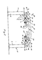
- the device for taking over a pallet 1 or the like from a movable first carrying device 2, in particular a trackless industrial truck 3, as shown in FIG. 2, preferably consists of a first, for example left device part 4 and a second, in this case right device part 5, which can be connected to one another in a manner not shown, for example via a base plate.
- Each of these device parts consists of the embodiment two strong stands 6 and 7, on which a cross member 8 rests. On the latter, a middle and two outer rollers 9 and 10 are mounted, which form a left and right roller conveyor 11 and 12 respectively.
- the rollers 9 and 10 are rotatably mounted on their axes and can be moved with the help of ball bushings (not shown) in the direction of the double arrow 13.
- the displacement takes place out of the drawn starting position against the resistance of a reset device 14, advantageously a spring.
- the axes 15 and 16 of the rollers 9 and 10 run in the horizontal direction and perpendicular to the direction of movement 18 of the pallet 1 when transferred to a second carrying device 19.
- the left and right rollers are arranged coaxially, with their free ends facing each other.
- the two roller conveyors 11 and 12 form a vertical centering device 20 for the pallet 1 lowered from above in the direction of arrow 21.
- the device also includes a horizontal centering device 22 for the pallet 1, which in an analogous manner consists of a left oblique roller conveyor 23 and a right oblique roller conveyor 24.
- Each of these two roller tracks is in turn made up of a plurality of obliquely arranged rollers 25 and 26, respectively.
- the rollers 25 are arranged in a gap with the rollers 9.
- the axes 27 and 28 of the rollers 25 and 26 form an angle with one another of preferably approximately 90 °.
- On the other hand forms a defined by the axes 25 plane with another plane through the axes 15 at an angle greater than 90 °, in the exemplary embodiment preferably about 135 0.
- rollers 25 and 26 are Slidably mounted on their axes in the direction of the double arrows 29 and 30, again using ball bushings or comparable devices. Their displacement also takes place against the resistance of return springs, which they preferably hold in a central position, just as with the rollers 9 and 10. For the sake of clarity, the springs are only partially drawn.
- the pallet 1 is aligned horizontally and vertically. Their longitudinal edges 31 and 32 on the underside of the pallet, both of which extend in the direction of movement 18, therefore lie precisely in the corner of the angularly arranged "support surfaces" defined by the horizontal and inclined rollers or their respective upper surface lines.
- the crossbeams 8, on which the rollers 9 and 10 are rotatably mounted can be moved and locked in the direction of the double arrows 33.
- the additional carriers 34 and 35, on which the obliquely arranged rollers 25 and 26 are mounted can also be displaced and locked on the cross members 8 in the direction of the arrows 33.
- the additional supports 34 and 35 can be pivoted in the direction of the double arrow 36.
- the lifting device 37 of the trackless industrial truck 3 projects through the space between the left and right halves of the centering devices 20 and 22 when the pallet 1 is retracted and lowered. The latter is driverless and is designed in the manner of a forklift truck due to this lifting device 37.
- the plate-like, movable carrying device 2 which loosely engages in the guide 38 or the like attached to the lower end of the pallet 1 or the like, so that the carrying device is released as soon as the pallet 1 or . Lies on the centering devices.
- the trackless industrial truck can then continue through the tunnel mentioned or move back again.
- Pallet 1 is a so-called workpiece clamping pallet, the guide 38 of which, for example, in cross section T- is shaped.
- a counter guide with the same profile is attached to the second support device 19.
- the latter is, for example, the processing table of a machine tool 39 (not shown in more detail).
- There is an extendable pulling device (not shown), for example a hydraulic or pneumatic cylinder, with which the pallet 1 or the like can be removed from the centering device 20, 22 can move over in the direction of arrow 18 so that the guide 38 of the pallet 1 comes into engagement with the counter-guide 40 of the second carrying device 19. In this way, millimeter-precise alignment of the pallet 1 with respect to the machine tool is possible.
Landscapes
- Engineering & Computer Science (AREA)
- Mechanical Engineering (AREA)
- Feeding Of Workpieces (AREA)
- Special Conveying (AREA)
- Warehouses Or Storage Devices (AREA)
Applications Claiming Priority (2)
| Application Number | Priority Date | Filing Date | Title |
|---|---|---|---|
| DE3115775 | 1981-04-18 | ||
| DE19813115775 DE3115775A1 (de) | 1981-04-18 | 1981-04-18 | "vorrichtung zum uebernehmen, ausrichten und uebergeben einer palette o.dgl." |
Publications (3)
| Publication Number | Publication Date |
|---|---|
| EP0063253A2 true EP0063253A2 (fr) | 1982-10-27 |
| EP0063253A3 EP0063253A3 (en) | 1982-12-08 |
| EP0063253B1 EP0063253B1 (fr) | 1985-06-26 |
Family
ID=6130477
Family Applications (1)
| Application Number | Title | Priority Date | Filing Date |
|---|---|---|---|
| EP82102434A Expired EP0063253B1 (fr) | 1981-04-18 | 1982-03-24 | Dispositif pour aligner et centrer automatiquement des pièces à usiner |
Country Status (5)
| Country | Link |
|---|---|
| US (1) | US4456418A (fr) |
| EP (1) | EP0063253B1 (fr) |
| CS (1) | CS257756B2 (fr) |
| DE (1) | DE3115775A1 (fr) |
| IT (1) | IT1190779B (fr) |
Cited By (4)
| Publication number | Priority date | Publication date | Assignee | Title |
|---|---|---|---|---|
| DE3345877A1 (de) * | 1983-12-19 | 1985-06-27 | Friedrich Kessler & Co, 8032 Gräfelfing | Vorrichtung zum exakten positionieren eines werkstuecks |
| GB2162450A (en) * | 1984-06-14 | 1986-02-05 | Cincinnati Milacron Inc | Method of moving a workpiece into a working station and apparatus for use in the method |
| EP0960687A3 (fr) * | 1998-05-29 | 2001-08-29 | FELSOMAT GmbH & Co. KG | Cellule d'automatisation pour manipuler des pieces |
| WO2020221470A1 (fr) * | 2019-05-02 | 2020-11-05 | Deckel Maho Pfronten Gmbh | Système comprenant un dispositif de transport servant à transporter un support pour produits à transporter, un support pour produits à transporter et un dispositif de logement |
Families Citing this family (13)
| Publication number | Priority date | Publication date | Assignee | Title |
|---|---|---|---|---|
| BE897462A (fr) * | 1983-08-04 | 1983-12-01 | Honda Motor Co Ltd | Appareil servant a fixer et a detacher des pieces d'oeuvre |
| US4915569A (en) * | 1987-02-05 | 1990-04-10 | Oerlikon Motch Corporation | Combination machine tool apparatus and pallet changing system |
| US4818171A (en) * | 1987-10-22 | 1989-04-04 | Caterpillar Industrial Inc. | Pallet transferring arrangement and method |
| GB8812634D0 (en) * | 1988-05-27 | 1988-06-29 | Caterpillar Ind Inc | Load positioning assembly & method |
| TW231282B (fr) * | 1991-11-12 | 1994-10-01 | Amada Co Ltd | |
| CA2165369A1 (fr) * | 1994-12-28 | 1996-06-29 | Krause Plow Corporation | Appareil multi-fonction de chargement et de recuperation |
| US5823733A (en) * | 1995-04-26 | 1998-10-20 | Kruzick; Kent | Vehicle mounted hoist with adjustable container supporting roller assemblies |
| US8089747B2 (en) * | 2009-05-22 | 2012-01-03 | Eaton Corporation | Power pedestal and system employing same |
| JP5912764B2 (ja) * | 2012-03-29 | 2016-04-27 | 平田機工株式会社 | 搬送ユニット及び搬送装置 |
| CN104339223B (zh) * | 2014-10-15 | 2016-08-31 | 金石机器人常州股份有限公司 | 防止缸盖反向通过的机构 |
| CN107479581B (zh) * | 2017-09-21 | 2021-01-26 | 北京京东尚科信息技术有限公司 | 货箱码放控制装置、系统、方法和存储介质 |
| DE102019104630B4 (de) * | 2019-02-25 | 2025-04-24 | POS GmbH & Co. KG | Anlage mit Anordnungen von Werkzeugmaschinen mit Speicher- und Positioniermitteln von Werkzeugen und/oder Werkstücken |
| CN114180258B (zh) * | 2021-11-10 | 2023-08-25 | 临泉晶宫绿建节能建筑有限公司 | 一种装配式建筑板材生产装置 |
Family Cites Families (15)
| Publication number | Priority date | Publication date | Assignee | Title |
|---|---|---|---|---|
| DE7117607U (de) * | 1971-12-23 | Wagner E Kg | Bewegbare Vorrichtung zum Transpor tieren, Übergeben von Gutern an Aufnahme Stationen und/oder Übernehmen von Gutern aus Abgabestationen | |
| US2815111A (en) * | 1954-11-03 | 1957-12-03 | Internat Staple And Machine Co | Conveyer centering device |
| FR1462390A (fr) * | 1965-11-03 | 1966-04-15 | Guilliet Ets | Dispositif pour le redressement et le centrage de pièces de bois relativement à unaxe de travail |
| DE1756752A1 (de) * | 1968-07-08 | 1970-05-06 | Demag Zug Gmbh | Leiteinrichtung fuer rechteckiges Foerdergut auf Foerderbahnen |
| DE6947589U (de) * | 1969-12-08 | 1970-03-26 | Enzinger Union Werke Ag | Vorrichtung an rollenfoerderbahnen zum selbsttaetigen ausrichten und zentrieren der gefoerderten stueckgueter |
| US3799370A (en) * | 1972-02-24 | 1974-03-26 | M Shell | Load transferring apparatus |
| US3856075A (en) * | 1973-01-16 | 1974-12-24 | S Larkin | Apparatus for preventing displacement of molds |
| US3869031A (en) * | 1973-04-04 | 1975-03-04 | Interlake Inc | Structure levelling assembly |
| DE2407173A1 (de) * | 1974-02-15 | 1975-08-28 | Stumpf Kg K | Ausrichtrollenbahn |
| DE2457600C3 (de) * | 1974-12-05 | 1978-07-27 | Dipl.-Ing. Otto Schulze-Berge Foerder- Und Lagertechnik, 4713 Bockum-Hoevel | Einsetzvorrichtung für Förderer zum Ausrichten von aufgebrachten Fördergütern |
| DD117059A1 (fr) * | 1974-12-24 | 1975-12-20 | ||
| US4278381A (en) * | 1976-10-08 | 1981-07-14 | White-Sundstrand Machine Tool, Inc. | Pallet shuttle system |
| JPS5350582A (en) * | 1976-10-19 | 1978-05-09 | Seiko Seiki Co Ltd | Pallet carrying and locating apparatus |
| DE7800169U1 (de) * | 1978-01-04 | 1979-06-07 | Fa. Ludwig Gurrath, 8532 Bad Windsheim | Auflage-profil fuer einfahr-palettenregale |
| DE2828559A1 (de) * | 1978-06-29 | 1980-01-17 | Ex Cell O Gmbh | Spanneinrichtung zum fixieren eines werkstueckes in einer vorbestimmten bearbeitungsstellung |
-
1981
- 1981-04-18 DE DE19813115775 patent/DE3115775A1/de not_active Withdrawn
-
1982
- 1982-03-24 EP EP82102434A patent/EP0063253B1/fr not_active Expired
- 1982-04-16 CS CS822749A patent/CS257756B2/cs unknown
- 1982-04-16 US US06/369,104 patent/US4456418A/en not_active Expired - Fee Related
- 1982-04-16 IT IT20797/82A patent/IT1190779B/it active
Cited By (7)
| Publication number | Priority date | Publication date | Assignee | Title |
|---|---|---|---|---|
| DE3345877A1 (de) * | 1983-12-19 | 1985-06-27 | Friedrich Kessler & Co, 8032 Gräfelfing | Vorrichtung zum exakten positionieren eines werkstuecks |
| GB2162450A (en) * | 1984-06-14 | 1986-02-05 | Cincinnati Milacron Inc | Method of moving a workpiece into a working station and apparatus for use in the method |
| EP0960687A3 (fr) * | 1998-05-29 | 2001-08-29 | FELSOMAT GmbH & Co. KG | Cellule d'automatisation pour manipuler des pieces |
| WO2020221470A1 (fr) * | 2019-05-02 | 2020-11-05 | Deckel Maho Pfronten Gmbh | Système comprenant un dispositif de transport servant à transporter un support pour produits à transporter, un support pour produits à transporter et un dispositif de logement |
| CN113795353A (zh) * | 2019-05-02 | 2021-12-14 | 德克尔马霍普夫龙滕有限公司 | 包括用于运输运输中货物的承载件的运输装置、运输中货物的承载件和接收设备的系统 |
| CN113795353B (zh) * | 2019-05-02 | 2024-05-10 | 德克尔马霍普夫龙滕有限公司 | 包括用于运输运输中货物的承载件的运输装置、运输中货物的承载件和接收设备的系统 |
| US12311491B2 (en) | 2019-05-02 | 2025-05-27 | Deckel Maho Pfronten Gmbh | System comprising a transport device for transporting a carrier for goods in transport, a carrier for goods in transport and a receiving apparatus |
Also Published As
| Publication number | Publication date |
|---|---|
| EP0063253A3 (en) | 1982-12-08 |
| DE3115775A1 (de) | 1982-11-11 |
| EP0063253B1 (fr) | 1985-06-26 |
| IT8220797A0 (it) | 1982-04-16 |
| US4456418A (en) | 1984-06-26 |
| IT1190779B (it) | 1988-02-24 |
| CS257756B2 (en) | 1988-06-15 |
Similar Documents
| Publication | Publication Date | Title |
|---|---|---|
| EP3268144B1 (fr) | Machine à dresser et procédé de remplacement d'éléments de roulement à dresser | |
| DE69003391T2 (de) | Pressenstrasseanordnung. | |
| EP0063253B1 (fr) | Dispositif pour aligner et centrer automatiquement des pièces à usiner | |
| EP0092685A1 (fr) | Dispositif de changement rapide et/ou serrage de moules pour machines à injection | |
| DE3202914A1 (de) | Laengsschneide- und/oder rillmaschine fuer bewegte materialbahnen, insbesondere fuer wellpappebahnen | |
| DE2622772B2 (de) | Einrichtung für den Transport und Wechsel von Walzen an Walzenbearbeitungsmaschinen | |
| EP0361179A2 (fr) | Dispositif de positionnement pour le transfert précis de pièces entre un chariot de transport et une installation fixe | |
| DE3142378A1 (de) | "maschine zur selbsttaetigen montage von reifen auf felgen" | |
| EP3563959A1 (fr) | Dispositif de sciage | |
| EP0838281A1 (fr) | Dispositif permettant de transferer des pièces dans une série de postes de travail | |
| DE8717649U1 (de) | Handhabungseinrichtung zum Wechseln der Werkzeuge einer Stanzpresse | |
| DE1777137A1 (de) | Verfahren und Vorrichtung zum genauen Einstellen eines Werkstueckes | |
| EP0270493B1 (fr) | Cisaille d'angle | |
| DE1300227B (de) | UEbergabevorrichtung fuer die drehungsfreie UEbergabe von Werkstuecken, insbesondere Fensterrahmen, Tueren u. dgl. | |
| DE29611728U1 (de) | Vorrichtung zum beidseitigen Beschleifen von Steinen | |
| EP2368647B1 (fr) | Système comprenant un support de cylindres et un dispositif de changement de cylindres | |
| EP3859176B1 (fr) | Rail télescopique | |
| DE2042733B2 (de) | Vorrichtung zum Quertransport und Übergabe von Strangpreßgut oder Walzgut, beispielsweise hinter einer Metallstrang presse | |
| DE3439969C2 (fr) | ||
| EP0202263B1 (fr) | Dispositif pour enlever des pieces et des supports de pieces d'une voie de transport | |
| DE202020101754U1 (de) | Wechselvorrichtung für einen Wechsel von wenigstens zwei Werkstückauflagen für eine Bearbeitungsmaschine | |
| DE2129689A1 (de) | Bandhaltevorrichtung | |
| EP0114174A1 (fr) | Presse à manufacturer des cadres | |
| DE102016216768B4 (de) | Fertigungsvorrichtung | |
| DE4211100C2 (de) | Abziehvorrichtung für die Einbaustücke von in einer Hürde in einem Walzwerk abgelegten Walzen |
Legal Events
| Date | Code | Title | Description |
|---|---|---|---|
| PUAI | Public reference made under article 153(3) epc to a published international application that has entered the european phase |
Free format text: ORIGINAL CODE: 0009012 |
|
| PUAL | Search report despatched |
Free format text: ORIGINAL CODE: 0009013 |
|
| AK | Designated contracting states |
Designated state(s): CH FR GB NL |
|
| AK | Designated contracting states |
Designated state(s): CH FR GB NL |
|
| 17P | Request for examination filed |
Effective date: 19821021 |
|
| GRAA | (expected) grant |
Free format text: ORIGINAL CODE: 0009210 |
|
| AK | Designated contracting states |
Designated state(s): CH FR GB LI NL |
|
| ET | Fr: translation filed | ||
| PLBE | No opposition filed within time limit |
Free format text: ORIGINAL CODE: 0009261 |
|
| STAA | Information on the status of an ep patent application or granted ep patent |
Free format text: STATUS: NO OPPOSITION FILED WITHIN TIME LIMIT |
|
| 26N | No opposition filed | ||
| PGFP | Annual fee paid to national office [announced via postgrant information from national office to epo] |
Ref country code: CH Payment date: 19910218 Year of fee payment: 10 |
|
| PGFP | Annual fee paid to national office [announced via postgrant information from national office to epo] |
Ref country code: GB Payment date: 19920317 Year of fee payment: 11 |
|
| PGFP | Annual fee paid to national office [announced via postgrant information from national office to epo] |
Ref country code: FR Payment date: 19920326 Year of fee payment: 11 |
|
| PG25 | Lapsed in a contracting state [announced via postgrant information from national office to epo] |
Ref country code: LI Effective date: 19920331 Ref country code: CH Effective date: 19920331 |
|
| PGFP | Annual fee paid to national office [announced via postgrant information from national office to epo] |
Ref country code: NL Payment date: 19920331 Year of fee payment: 11 |
|
| REG | Reference to a national code |
Ref country code: CH Ref legal event code: PL |
|
| PG25 | Lapsed in a contracting state [announced via postgrant information from national office to epo] |
Ref country code: GB Effective date: 19930324 |
|
| PG25 | Lapsed in a contracting state [announced via postgrant information from national office to epo] |
Ref country code: NL Effective date: 19931001 |
|
| NLV4 | Nl: lapsed or anulled due to non-payment of the annual fee | ||
| GBPC | Gb: european patent ceased through non-payment of renewal fee |
Effective date: 19930324 |
|
| PG25 | Lapsed in a contracting state [announced via postgrant information from national office to epo] |
Ref country code: FR Effective date: 19931130 |
|
| REG | Reference to a national code |
Ref country code: FR Ref legal event code: ST |