EP0063307A2 - Alimentation en composants - Google Patents
Alimentation en composants Download PDFInfo
- Publication number
- EP0063307A2 EP0063307A2 EP82102918A EP82102918A EP0063307A2 EP 0063307 A2 EP0063307 A2 EP 0063307A2 EP 82102918 A EP82102918 A EP 82102918A EP 82102918 A EP82102918 A EP 82102918A EP 0063307 A2 EP0063307 A2 EP 0063307A2
- Authority
- EP
- European Patent Office
- Prior art keywords
- pallet
- path
- pallets
- movement
- transition
- Prior art date
- Legal status (The legal status is an assumption and is not a legal conclusion. Google has not performed a legal analysis and makes no representation as to the accuracy of the status listed.)
- Granted
Links
- 230000007704 transition Effects 0.000 claims abstract description 57
- 238000006073 displacement reaction Methods 0.000 claims description 13
- 230000002093 peripheral effect Effects 0.000 claims description 4
- 230000001360 synchronised effect Effects 0.000 description 2
- 240000008415 Lactuca sativa Species 0.000 description 1
- 230000005484 gravity Effects 0.000 description 1
- 230000002028 premature Effects 0.000 description 1
- 235000012045 salad Nutrition 0.000 description 1
Images


Classifications
-
- H—ELECTRICITY
- H05—ELECTRIC TECHNIQUES NOT OTHERWISE PROVIDED FOR
- H05K—PRINTED CIRCUITS; CASINGS OR CONSTRUCTIONAL DETAILS OF ELECTRIC APPARATUS; MANUFACTURE OF ASSEMBLAGES OF ELECTRICAL COMPONENTS
- H05K13/00—Apparatus or processes specially adapted for manufacturing or adjusting assemblages of electric components
- H05K13/0053—Arrangements for assisting the manual mounting of components, e.g. special tables or light spots indicating the place for mounting
Definitions
- the invention relates to a parts feed, in particular for an assembly table for circuit boards, comprising a plurality of elongated pallets provided with part receptacles, possibly integral with the vessels, one approximating the pallets which are essentially parallel to one another along a path loop with two parallel to the pallet longitudinal direction vertical movement paths and two transition paths connecting the movement paths and a guide for driving the pallets along the path loop, each with a drive element in the area of the two transition paths, which adjoins the pallet located in the transition path.
- this alternating drive of the pallets in the movement paths and the transition paths is achieved by a two-part drive.
- the two drive elements used to move the pallets along the transition tracks are formed by a pull chain which engages on the outer longitudinal sides of the pallets.
- the shifting of the pallets within the movement paths' by one pallet width each serve two drive cranks at one end of each of the two movement paths, which act on webs which are formed on the underside of the pallet.
- This known drive is mechanically complex, since a total of four drive cranks and the pull chain must be driven in a precisely coordinated manner. Synchronization errors can cause damage; If, for example, the pull chain is stopped too late, the pallets carried along by the chain hit hard against the lateral boundaries of the movement paths. tion of the type mentioned with a simplified structure of the drive.
- the pallet at the opposite end of the movement path mentioned in this displacement movement is pushed into the subsequent deflection path until it comes into engagement with the drive element there.
- This pallet can then be moved along this transition path by the drive element.
- the respective notching of the pallets within the deflection tracks before reaching the The nearest normal position exactly one pallet width from the transition path in the direction of the pallet width, ensures that the pallet then moved into the normal position is out of engagement with this drive element and therefore does not hinder its conveying movement when the next pallet is moved along the transition path.
- the displacement distance taken in the direction of the pallet width of a pallet moved from a transition path into one of the release positions is greater than the displacement distance taken in the direction of the pallet width of a pallet moved from a normal position at the end of a movement path into one of the notch positions. This measure ensures precise synchronization of the pallet movement. If a pallet that is currently driven by one of the drive elements is approaching a notching point, the subsequent pallet comes into engagement with the drive element before the leading pallet disengages. The drive times of subsequent pallets therefore overlap.
- the end regions of the pallets and, if applicable, the deflection tracks be designed in such a way that when they are latched in towards the nearest one transition path immediately "palette approaching this lies on the leading pallet, driven by the nearest drive element, preferably over tapered pallet corner areas of both pallets, or the leading pallet follows with a small clearance clearance such that the trailing pallet moves automatically into the latching position the leading pallet is prevented.
- the movement of successive pallets is thus synchronized in such a way that the pallets follow one another directly as they run along the web loop, and in such a way that a pallet located in the non-driven and therefore critical area between a latching or unlatching position and the closest normal position reliably depends on each is brought into the normal position or into engagement with the drive element according to the direction of movement, it being excluded that the pallet unintentionally comes into engagement with the drive element, for example due to vibrations.
- the pallet corner area be formed by a bevel that extends from the pallet side surface and that passes over a rounded area into the pallet end face.
- the release position is essentially identical to the notch position and is possibly closer to the movement path than the transition path in the direction of the pallet width.
- the asymmetrical position ensures that a pallet disengages at a later time than the following pallet engages.
- the pallets are each formed with a driving shoulder which is elongate in the longitudinal direction of the pallet and has an engagement surface for the drive elements which extends in the movement path and that the drive elements arranged in the region of the center of length of the respective transition path move the pallets along this transition path at the center of the Roll off the side surface of the drive shoulder facing the web loop.
- the drive shoulder can be designed with a circumferential toothing, which can preferably consist of two parallel 'essentially straight longitudinal toothings and two end toothings connecting them, preferably describing a semicircular arc or tapering.
- the entrainment can also be designed differently, preferably as a row of pins.
- a chain or a toothed belt which surrounds deflection rollers in the area of the center length, can be used as drive elements the transition railroad is guided.
- the two drive elements are formed by two synchronously driven gear wheels. If both gears are coupled to one another by means of toothed belts, only a motor drive is required.
- each with a guide groove groove tracks are provided in the base, the respective shape of which corresponds essentially to the shape of the track loop and that each pallet is provided with two guide elements which each engage in an associated guide groove.
- a preferred embodiment is characterized in that the guide grooves intersect at such a large angle that threading a guide element into the guide groove assigned to the other guide element is substantially excluded during operation. The angle is preferably about 70 °.
- the guide elements each have a pivotable guide boat inserted into the guide groove.
- the guide grooves are undercut.
- the guide elements be designed with rotatably mounted guide rollers, the diameter of which se r is slightly smaller than the width of the guide groove or the groove mouth of the undercut guide groove and that the guide rollers engage in the guide groove or the groove mouth.
- the assembly table 10 shown in FIG. 1 is used to equip a circuit board 12 which is attached to a schematically indicated holder 14.
- a light head 16 serving to display the respective assembly location is attached to the top of the assembly table 10 via a holding arm 15 and a base plate 18.
- two such components 24 are already attached to the circuit board.
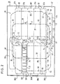
- a parts feed 28 shown roughly schematically in dashed lines in FIG. 1 and arranged within the actual table top 26. 2 shows the structure of the parts feeder 28.
- the removal opening 20 above the parts feed 28 is indicated by a dotted line.
- the parts feeder 28 consists of a multiplicity (here twelve) of pallets 30 which carry interchangeable part receptacles 32. As can be seen from FIG. 4, each pallet 30 is provided with a continuous parts receptacle 32, which is divided into a plurality (here nine) of compartments 34.
- a pallet 30 is provided with such a parts receptacle 32 in FIG. 2.
- a parts receptacle 32 instead of a single continuous part receptacle 32, several individual part receptacles can also be placed next to one another on the pallets 30.
- the dimensions of the openings of the compartments 34 correspond to the dimensions of the removal opening 20.
- the pallets 30 are guided along an approximately rectangular web loop during operation.
- the curve 36 indicated in FIG. 2 with a dot-dot-dash line, which describes the path of the center of gravity S of the pallets 30, can be equated with the path loop.
- the parts of the path loop 36 which run from top to bottom in FIG. 2 are to be referred to as movement paths 38 and the parts which run from right to left as transition paths 40.
- the corner areas of the loop 36 are rounded from g and are referred to as deflection tracks 39.
- the pallets 30 In the movement paths 38, the pallets 30 abut one another and are shifted together, whereas in the transition paths one pallet is shifted from one movement path 38 to the other.
- the displacement movements in the two transition tracks 40 are in opposite directions, as are those in the movement tracks 38.
- the track loop 36 can be moved alternately in one direction and in the other direction by the pallets 30.
- the pallet 30 located in the transition path 40 carries out a linear displacement movement, sliding along the side surfaces of the pallets 30 of the two movement paths 38 facing this pallet.
- the pallet 30 is still offset inwards relative to the pallets 30 of the subsequent movement path 36.
- the pallet 30 is offset exactly by one pallet width from its position in the previous transition path 40 and is now aligned with the other pallets 30 of the movement path 38.
- each groove track consists of a guide groove 48, the structure of which is shown in FIGS. 5 and 6.
- Two angular elements 50 which are essentially L-shaped in cross section are at a distance of attached to each other on the base plate 42 with horizontal legs 52 facing away from each other.
- the free ends 53 of the vertical legs 54 are bent approximately U-shaped towards the other angle 50.
- an undercut guide groove 56 is therefore formed between the angles 50 and a groove opening 58 between the ends 53.
- each pallet 30 carries on its underside two guide elements 60 which engage in the guide groove 48 of the groove track 44 and the groove track 46, respectively. 2, the guide elements 60 are each indicated with a small circle.
- the two groove tracks 46 and 48 are offset from one another in such a way that the groove tracks 46 and 48 intersect at a relatively large angle a, which is approximately 70 ° (see also FIG. 6 ).
- FIG. 5 The structure of a guide element 60 is shown in FIG. 5.
- a guide roller 68 and a guide boat 70 are then attached to the underside of the pallet 30.
- the ball-bearing guide roller 68 engages in the already mentioned groove mouth 58, its diameter being slightly smaller than the width of the groove mouth.
- the guide boat 70 which is also rotatably mounted, is shown in an enlarged scale in a top view in FIG. 6.
- the guide boat 70 is elongated.
- the width of the guide boat 70 is adapted to the width of the guide groove 56. So that there is no jamming of the guide boat 70 in rounded parts of the groove tracks 44 and 46, the guide boat 70 is rounded toward the outside, ie away from the center of the guide tracks 44 and 46.
- FIG. 6 shows two guide boats 70, the position of which corresponds to the pallet arrangement shown in FIG. 2. To prevent a movement of the bottom pallet 30 to the left to a collision of the shuttle 70 running in the groove 46 of this pallet 30 with the shuttle 70 shown at the top right in FIG. 6, the shuttle 70 are each on one of them Shortened ends accordingly.
- the pallets 30 are driven by two gear wheels 72 and 74, which are rotatably mounted on the base plate 42 with a vertical axis.
- One of the gears, the upper gear 72 in FIG. 2, can be rotated by means of a pinion 78 driven by a motor 76.
- an auxiliary gear 80 which is non-rotatable, is indicated on the underside of the gear 72.
- a corresponding auxiliary gear 80 is also attached to the other gear 74.
- a toothed belt 82 indicated with a broken line in FIG. 2 ensures synchronous movement of both toothed wheels 72 and 74.
- the pallet 30 c In the starting position shown in FIG. 2, the pallet 30 c is just at the end of its cyclical movement along the lower transition path 40 and lies laterally against the pallet 30 d at the lower end of the right movement path 36 in FIG. 2.
- the position of this pallet 30 d and the other pallets 30 e to 30 h and 30 k to 30 b is referred to as the normal position.
- this movement path palette If the two transfer orbit pallets 30 c and 30 i freely back along the crossing path 40 move back and forth, whereby they, however, the side of the nearest pallets abut angsbahnen about g. This movement is effected by the two gear wheels 72 and 74, which engage in the peripheral toothing 92 of the two pallets.
- the peripheral teeth 92 of the adjacent pallets 30 b and 30 d and 30 h and 30 k are out of engagement with the gear 74 and 72.
- the gear 74 coupled to the gear 72 via the toothed belt 82 also rotates in the same sense, with the result that the pallet 30 c (and accordingly the pallet 30 i) moves further to the right in the direction of the arrow C, it now being in the deflection path 39.
- the guide element 60 arranged at the inner end of the pallet 30 c reaches a rounded corner region 98 of the groove track 44, whereas the other guide element 60 runs into a comparatively more angled rectilinear corner area 95 of the groove track 46.
- the outer end of the pallet 30 c which is remote from the gear 74, therefore carries out a slight pivoting movement in the counterclockwise direction. Accordingly, the pallet 30 d and the pallets 30 i to 30 h of the right movement path 38 following this are pivoted.
- the toothing of the toothed wheel 74 no longer engages in the section of the circumferential toothing 92 formed on the inner side surface 88, but in the toothing section adjoining it and formed on the half-cylinder surface 90.
- the uppermost pallet is pushed 30 h into the next deflecting path 39 and soon reaches a latching position in which the gear 72 engages the peripheral toothing. 92 of this pallet 30 h.
- the pallet 30 c remains in engagement with the gear 74 in the meantime , because it does not reach its release position in the movement sequence until later. Since the pallet 30 c corresponds to the movement sequence of the pallet 30 c and the pallet 30 h corresponds to the pallet 30 b, the gear 74 is now in engagement with the pallets 30 c and 30 b and the gear 72 accordingly with the pallets 30 h and 30 i.
- Fi g. 3A shows a moment in which the pallet 30 b is already in full engagement with the toothed wheel 74 and is pivoted downward to the right by the latter. With the pallet 30 c, the gear 74 is still in full engagement. With a further rotation of the pinion 74, the situation shown in Fig. 3 B, in which the pallet 30 c immediately before the disengagement of the gear 74 is obtained (Ausklinkwolf). In this position or immediately after notching, there is a risk that the teeth will mesh incorrectly ("tooth salad”) if the pallet that is no longer driven by the gear wheel 74 either due to a sudden vibration or a change in direction of the drive moved back to gear 74.
- the pallet corner areas are chamfered in the manner shown in FIG. 3B.
- a rounded region 99 adjoins a pallet end face 97 at both corners.
- These areas 99 each merge into a bevel 101, which each form an angle ⁇ with the adjoining pallet side surface 89.
- the successive pallets 30 b and 30 c touch on the rounded areas; the bevels 101 then slide off one another, which leads to the desired displacement of the pallet 30 c from the release position shown in FIG. 3B to the normal position according to FIG. 3C at the lower end of the following movement path 38.
- the pallet 30 b has reached the transition path 40 and can now be moved further to the right below the removal opening 20 in accordance with its division in the longitudinal direction of the pallet. It is possible that the right end of this pallet 30 b presses the outer end of the pallet 30 c, which may not yet be pivoted far enough upwards, into the normal position. To facilitate this, the pallets 30 can be provided with a slight waist (dotted outline of the pallet 30 d in FIG. 3C) in order to keep the moments at the beginning of the displacement movement of the pallet 30 b in the transition path 40 low. The outer end of the pallet 30 c and the corresponding ends of the pallets 30 d to 30 g preceding in the movement path 38 are accordingly pivoted upwards in two steps.
- a first step at the beginning of the movement of the pallet 30 c the outer end runs ahead of the inner one, which is due to the comparatively greater slope (corner region 95) of the groove track 46 assigned to the guide element 60 at the outer end of the pallet.
- the outer end which has been overhauled in the meantime by the inner end, is then pushed upwards from the subsequent pallet in the second step after the inner end has already been released.
- one of the two steps can be dispensed with if the pivoting movement achievable by the other step is correspondingly large.
- FIG. 7 schematically shows a further embodiment of a parts feed.
- a chain 174 is provided which engages in a circumferential toothing 192 of a pallet 130 which is adapted to this chain.
- the chain 174 in its lower part shown in FIG. 7 (which corresponds to the upper part) is guided over a central deflecting roller 175 and two lateral deflecting rollers 176.
- the pallet 130 is currently on a deflection path. If it is subsequently moved in the direction of the arrow, the increasing distance between the chain 174 and the groove track 144 leads to the circumferential toothing coming out of contact with the chain 174 before the movement path is reached.
- the functional principle of the parts feed according to FIG. 7 corresponds to that of the parts feed described above with reference to FIGS. 1 to 6.
- the shoulder 84 carrying the circumferential toothing 92 can also be replaced by a row of vertical pins running in the longitudinal direction of the pallet, into which corresponding toothed wheels 72 and 74 can engage.
Landscapes
- Engineering & Computer Science (AREA)
- Manufacturing & Machinery (AREA)
- Microelectronics & Electronic Packaging (AREA)
- Automatic Assembly (AREA)
- Ignition Installations For Internal Combustion Engines (AREA)
- Confectionery (AREA)
- Braking Systems And Boosters (AREA)
- Feeding Of Workpieces (AREA)
- Branching, Merging, And Special Transfer Between Conveyors (AREA)
Priority Applications (1)
| Application Number | Priority Date | Filing Date | Title |
|---|---|---|---|
| AT82102918T ATE31860T1 (de) | 1981-04-07 | 1982-04-05 | Teilezufuehrung. |
Applications Claiming Priority (2)
| Application Number | Priority Date | Filing Date | Title |
|---|---|---|---|
| DE3114032A DE3114032C2 (de) | 1981-04-07 | 1981-04-07 | Teilezuführung für einen Bestückungstisch |
| DE3114032 | 1981-04-07 |
Publications (3)
| Publication Number | Publication Date |
|---|---|
| EP0063307A2 true EP0063307A2 (fr) | 1982-10-27 |
| EP0063307A3 EP0063307A3 (en) | 1984-11-21 |
| EP0063307B1 EP0063307B1 (fr) | 1988-01-07 |
Family
ID=6129580
Family Applications (1)
| Application Number | Title | Priority Date | Filing Date |
|---|---|---|---|
| EP82102918A Expired EP0063307B1 (fr) | 1981-04-07 | 1982-04-05 | Alimentation en composants |
Country Status (4)
| Country | Link |
|---|---|
| US (1) | US4466530A (fr) |
| EP (1) | EP0063307B1 (fr) |
| AT (1) | ATE31860T1 (fr) |
| DE (2) | DE3114032C2 (fr) |
Cited By (1)
| Publication number | Priority date | Publication date | Assignee | Title |
|---|---|---|---|---|
| WO1988002532A1 (fr) * | 1986-09-23 | 1988-04-07 | David Briscoe | Systeme d'echange et de stockage de panneaux publicitaires |
Families Citing this family (10)
| Publication number | Priority date | Publication date | Assignee | Title |
|---|---|---|---|---|
| US4715286A (en) * | 1985-11-27 | 1987-12-29 | General Electric Company | Conveyer system |
| US5024318A (en) * | 1988-05-18 | 1991-06-18 | Schwarze Ralph W | Conveyor storage apparatus |
| US5191694A (en) * | 1991-07-03 | 1993-03-09 | Shape Inc. | Cassette assembly line |
| DK171271B1 (da) * | 1994-06-14 | 1996-08-19 | Hoejvang Maskinfab Aps | Magasinindretning |
| US5611422A (en) * | 1995-03-01 | 1997-03-18 | Fab-Tech Industries, Inc. | Materials carrying apparatus |
| US6942738B1 (en) | 1996-07-15 | 2005-09-13 | Semitool, Inc. | Automated semiconductor processing system |
| US6279724B1 (en) * | 1997-12-19 | 2001-08-28 | Semitoll Inc. | Automated semiconductor processing system |
| US6723174B2 (en) | 1996-03-26 | 2004-04-20 | Semitool, Inc. | Automated semiconductor processing system |
| AU2001268656A1 (en) * | 2000-07-07 | 2002-01-21 | Semitool, Inc. | Automated processing system |
| DE102021122976A1 (de) | 2021-09-06 | 2023-03-09 | Technische Hochschule Ostwestfalen-Lippe, Körperschaft des öffentlichen Rechts | Montagearbeitsplatz sowie Montageverfahren |
Family Cites Families (4)
| Publication number | Priority date | Publication date | Assignee | Title |
|---|---|---|---|---|
| US3418084A (en) * | 1966-10-27 | 1968-12-24 | Instrumentation Specialties Co | Rectangular fraction collector |
| US4029961A (en) * | 1975-04-11 | 1977-06-14 | Wilhelm Lohr | Apparatus for measuring the nuclear radiation of a sequence of radioactive samples |
| DE2716548C3 (de) * | 1977-04-14 | 1986-05-07 | Royonic Elektronik-Produktionsmaschinen GmbH, 8057 Eching | Einrichtung zur Erzeugung einer Bestückungsortsanzeige für eine mit elektrischen Bauelementen zu bestückende Schaltungsträgerplatte |
| DE2856109C3 (de) * | 1978-12-23 | 1981-11-12 | Standard Elektrik Lorenz Ag, 7000 Stuttgart | Bestückungstisch zur manuellen Bestückung von Trägerplatten, insbesondere von Leiterplatten |
-
1981
- 1981-04-07 DE DE3114032A patent/DE3114032C2/de not_active Expired
-
1982
- 1982-03-17 US US06/359,166 patent/US4466530A/en not_active Expired - Fee Related
- 1982-04-05 AT AT82102918T patent/ATE31860T1/de not_active IP Right Cessation
- 1982-04-05 EP EP82102918A patent/EP0063307B1/fr not_active Expired
- 1982-04-05 DE DE8282102918T patent/DE3277960D1/de not_active Expired
Cited By (1)
| Publication number | Priority date | Publication date | Assignee | Title |
|---|---|---|---|---|
| WO1988002532A1 (fr) * | 1986-09-23 | 1988-04-07 | David Briscoe | Systeme d'echange et de stockage de panneaux publicitaires |
Also Published As
| Publication number | Publication date |
|---|---|
| DE3114032A1 (de) | 1982-11-04 |
| DE3277960D1 (en) | 1988-02-11 |
| EP0063307A3 (en) | 1984-11-21 |
| DE3114032C2 (de) | 1983-04-14 |
| US4466530A (en) | 1984-08-21 |
| ATE31860T1 (de) | 1988-01-15 |
| EP0063307B1 (fr) | 1988-01-07 |
Similar Documents
| Publication | Publication Date | Title |
|---|---|---|
| EP0642458B1 (fr) | Bac de stockage comportant une zone de prehension pour un dispositif de manutention | |
| DE3915217A1 (de) | Verfahren und vorrichtung zum sortieren von gegenstaenden | |
| EP0351633A2 (fr) | Dispositif pour le transport de pièces d'ouvrage | |
| EP0063307B1 (fr) | Alimentation en composants | |
| DE2603237A1 (de) | Vorrichtung zum paarweisen zusammensetzen und stapeln von formteilen | |
| DE4211658A1 (de) | Vorschubeinrichtung für Tafeln | |
| DE69024538T2 (de) | Kassettenladegerät | |
| DE69200723T2 (de) | Vorrichtung zum Aufnehmen und synchronisierten Überführen verschiedener Gegenstände. | |
| DE3239159C2 (de) | Vorrichtung zum Anbringen von mehrteiligen Verschlüssen an Kleidungsstücken | |
| DE69304614T2 (de) | Stangzufuhrvorrichtung für Stangenschubvorrichtungen an Werkzeugmaschinen | |
| DE2245193A1 (de) | Selbsttaetige maschine zum transport von foerdergut von einer foerdereinrichtung zu einer anderen foerdereinrichtung | |
| DE2259273C2 (de) | Vorrichtung zum Ausschleusen von Stückgut aus einer Rollenbahn | |
| EP1318958A1 (fr) | Procede et dispositif d'apport d'objets reguliers a une station de travail | |
| DE19546887A1 (de) | Förderbahn für Paletten | |
| DE1456663C3 (de) | Einrichtung zum genauen Positionieren von mit Werkstücken, z.B. gleichartigen Kleinapparaten beladenen Werkstückträgern | |
| EP0065080A1 (fr) | Système de transport avec une voie de transport pour des pièces à travailler et/ou des porte-pièces | |
| DE4125666C1 (en) | Bottle aligner positioner turret head - has concentric rim plates recessed to hold conveyed bottle with guides on each plate riding over surface fixed concentric to turret | |
| DE1940287A1 (de) | Automatische Abfuell- und Verschliessmaschine | |
| DE1303853B (fr) | ||
| EP0392223B1 (fr) | Dispositif pour verrouiller de façon détachable le couvercle au boîtier d'une armature lumineuse allongée | |
| DE2218748C3 (de) | Kopplungsvorrichtung für einen Malteserkreuz-Antrieb | |
| DE1499551B2 (de) | Muenzsortier und muenzzaehlmaschine | |
| DE2713660B2 (de) | Kettenantrieb für einen WerkstückÜbertragungsmechanismus | |
| DE4009150C1 (en) | Corner section for kitchen cupboard - has carousel with vertical rotary column carrying horizontal plate | |
| DE3545835C2 (fr) |
Legal Events
| Date | Code | Title | Description |
|---|---|---|---|
| PUAI | Public reference made under article 153(3) epc to a published international application that has entered the european phase |
Free format text: ORIGINAL CODE: 0009012 |
|
| AK | Designated contracting states |
Designated state(s): AT BE CH DE FR GB IT LI NL SE |
|
| PUAL | Search report despatched |
Free format text: ORIGINAL CODE: 0009013 |
|
| AK | Designated contracting states |
Designated state(s): AT BE CH DE FR GB IT LI NL SE |
|
| 17P | Request for examination filed |
Effective date: 19850108 |
|
| 17Q | First examination report despatched |
Effective date: 19860625 |
|
| GRAA | (expected) grant |
Free format text: ORIGINAL CODE: 0009210 |
|
| AK | Designated contracting states |
Kind code of ref document: B1 Designated state(s): AT BE CH DE FR GB IT LI NL SE |
|
| PG25 | Lapsed in a contracting state [announced via postgrant information from national office to epo] |
Ref country code: BE Effective date: 19880107 |
|
| REF | Corresponds to: |
Ref document number: 31860 Country of ref document: AT Date of ref document: 19880115 Kind code of ref document: T |
|
| ITF | It: translation for a ep patent filed | ||
| REF | Corresponds to: |
Ref document number: 3277960 Country of ref document: DE Date of ref document: 19880211 |
|
| ET | Fr: translation filed | ||
| GBT | Gb: translation of ep patent filed (gb section 77(6)(a)/1977) | ||
| PG25 | Lapsed in a contracting state [announced via postgrant information from national office to epo] |
Ref country code: AT Effective date: 19880405 |
|
| PLBE | No opposition filed within time limit |
Free format text: ORIGINAL CODE: 0009261 |
|
| STAA | Information on the status of an ep patent application or granted ep patent |
Free format text: STATUS: NO OPPOSITION FILED WITHIN TIME LIMIT |
|
| PG25 | Lapsed in a contracting state [announced via postgrant information from national office to epo] |
Ref country code: GB Effective date: 19881121 |
|
| 26N | No opposition filed | ||
| GBPC | Gb: european patent ceased through non-payment of renewal fee | ||
| REG | Reference to a national code |
Ref country code: CH Ref legal event code: PUE Owner name: ROYOCAD GESELLSCHAFT FUER HARD- UND SOFTWARE MBH |
|
| NLS | Nl: assignments of ep-patents |
Owner name: ROYOCAD GESELLSCHAFT FUER HARD- UND SOFTWARE MBH T |
|
| ITPR | It: changes in ownership of a european patent |
Owner name: CESSIONE;ROYOCAD GESELLSCHAFT FUR HARD - UND SOFTW |
|
| REG | Reference to a national code |
Ref country code: FR Ref legal event code: TP |
|
| PGFP | Annual fee paid to national office [announced via postgrant information from national office to epo] |
Ref country code: SE Payment date: 19930428 Year of fee payment: 12 |
|
| ITTA | It: last paid annual fee | ||
| PG25 | Lapsed in a contracting state [announced via postgrant information from national office to epo] |
Ref country code: SE Effective date: 19940406 |
|
| PGFP | Annual fee paid to national office [announced via postgrant information from national office to epo] |
Ref country code: CH Payment date: 19940426 Year of fee payment: 13 |
|
| PGFP | Annual fee paid to national office [announced via postgrant information from national office to epo] |
Ref country code: FR Payment date: 19940429 Year of fee payment: 13 |
|
| PGFP | Annual fee paid to national office [announced via postgrant information from national office to epo] |
Ref country code: NL Payment date: 19940430 Year of fee payment: 13 |
|
| PGFP | Annual fee paid to national office [announced via postgrant information from national office to epo] |
Ref country code: DE Payment date: 19940505 Year of fee payment: 13 |
|
| EUG | Se: european patent has lapsed |
Ref document number: 82102918.8 Effective date: 19941110 |
|
| PG25 | Lapsed in a contracting state [announced via postgrant information from national office to epo] |
Ref country code: LI Effective date: 19950430 Ref country code: CH Effective date: 19950430 |
|
| PG25 | Lapsed in a contracting state [announced via postgrant information from national office to epo] |
Ref country code: NL Effective date: 19951101 |
|
| REG | Reference to a national code |
Ref country code: CH Ref legal event code: PL |
|
| PG25 | Lapsed in a contracting state [announced via postgrant information from national office to epo] |
Ref country code: FR Effective date: 19951229 |
|
| NLV4 | Nl: lapsed or anulled due to non-payment of the annual fee |
Effective date: 19951101 |
|
| PG25 | Lapsed in a contracting state [announced via postgrant information from national office to epo] |
Ref country code: DE Effective date: 19960103 |
|
| REG | Reference to a national code |
Ref country code: FR Ref legal event code: ST |