EP0063375B1 - Système de commande d'injection pour pompe d'injection Diesel commandée par une valve électromagnétique - Google Patents
Système de commande d'injection pour pompe d'injection Diesel commandée par une valve électromagnétique Download PDFInfo
- Publication number
- EP0063375B1 EP0063375B1 EP82103274A EP82103274A EP0063375B1 EP 0063375 B1 EP0063375 B1 EP 0063375B1 EP 82103274 A EP82103274 A EP 82103274A EP 82103274 A EP82103274 A EP 82103274A EP 0063375 B1 EP0063375 B1 EP 0063375B1
- Authority
- EP
- European Patent Office
- Prior art keywords
- fuel
- electromagnetic valve
- fuel supply
- valve
- pressure chamber
- Prior art date
- Legal status (The legal status is an assumption and is not a legal conclusion. Google has not performed a legal analysis and makes no representation as to the accuracy of the status listed.)
- Expired
Links
Images




Classifications
-
- F—MECHANICAL ENGINEERING; LIGHTING; HEATING; WEAPONS; BLASTING
- F02—COMBUSTION ENGINES; HOT-GAS OR COMBUSTION-PRODUCT ENGINE PLANTS
- F02D—CONTROLLING COMBUSTION ENGINES
- F02D41/00—Electrical control of supply of combustible mixture or its constituents
- F02D41/30—Controlling fuel injection
- F02D41/38—Controlling fuel injection of the high pressure type
- F02D41/40—Controlling fuel injection of the high pressure type with means for controlling injection timing or duration
- F02D41/406—Electrically controlling a diesel injection pump
- F02D41/408—Electrically controlling a diesel injection pump of the distributing type
-
- F—MECHANICAL ENGINEERING; LIGHTING; HEATING; WEAPONS; BLASTING
- F02—COMBUSTION ENGINES; HOT-GAS OR COMBUSTION-PRODUCT ENGINE PLANTS
- F02B—INTERNAL-COMBUSTION PISTON ENGINES; COMBUSTION ENGINES IN GENERAL
- F02B1/00—Engines characterised by fuel-air mixture compression
- F02B1/02—Engines characterised by fuel-air mixture compression with positive ignition
- F02B1/04—Engines characterised by fuel-air mixture compression with positive ignition with fuel-air mixture admission into cylinder
-
- F—MECHANICAL ENGINEERING; LIGHTING; HEATING; WEAPONS; BLASTING
- F02—COMBUSTION ENGINES; HOT-GAS OR COMBUSTION-PRODUCT ENGINE PLANTS
- F02B—INTERNAL-COMBUSTION PISTON ENGINES; COMBUSTION ENGINES IN GENERAL
- F02B3/00—Engines characterised by air compression and subsequent fuel addition
- F02B3/06—Engines characterised by air compression and subsequent fuel addition with compression ignition
-
- Y—GENERAL TAGGING OF NEW TECHNOLOGICAL DEVELOPMENTS; GENERAL TAGGING OF CROSS-SECTIONAL TECHNOLOGIES SPANNING OVER SEVERAL SECTIONS OF THE IPC; TECHNICAL SUBJECTS COVERED BY FORMER USPC CROSS-REFERENCE ART COLLECTIONS [XRACs] AND DIGESTS
- Y02—TECHNOLOGIES OR APPLICATIONS FOR MITIGATION OR ADAPTATION AGAINST CLIMATE CHANGE
- Y02T—CLIMATE CHANGE MITIGATION TECHNOLOGIES RELATED TO TRANSPORTATION
- Y02T10/00—Road transport of goods or passengers
- Y02T10/10—Internal combustion engine [ICE] based vehicles
- Y02T10/40—Engine management systems
Definitions
- the present invention relates to a fuel injection method for diesel engines and a fuel injection apparatus according to the precharacterizing parts of the claims 1 and 2 respectively.
- Such a method and an apparatus are known from the US-A-3 107 661.
- the diesel engine does not use any spark plug but a spray of fuel is injected into a cylinder when the air therein is compressed to high temperature and high pressure, which causes ignition and explosion of the injection fuel thereby driving the piston.
- the ignition timing thus depends on the time of fuel injection into the cylinder.
- the ignition timing is desired to be advanced in accordance with the rotational speed of the engine and the load or the amount of fuel to be injected. This advancement of the ignition timing is accomplished by advancing the fuel injection timing by the fuel injection pump.
- the US-A-3 107 661 discloses that the fuel supply from the cylinder 45 determines the amount of fuel injection and the fuel supply from the cylinder 44 determines the timing of injection, i.e. the advance angle of fuel injection. This document, however, fails to teach or suggest how to prevent interference between the fuel supply from the cylinder 45 and from the cyliner 44.
- Figs. 8a and 8b are graphs showing the fuel injection amount and the advance characteristics of fuel injection timing with respect to the engine rotational speed respectively.
- a rotor 1 rotates in synchronism with a diesel engine by a drive shaft (not shown).
- An end of the rotor 1 is formed with a through hole along the diameter, the through hole having a cylindrical central portion 50 and opposite end portions 51 with a rectangular section.
- a pair of radially-slidable plungers 2 In the central portion 50, are mounted a pair of radially-slidable plungers 2, and in each end portion 51 is mounted a radially-slidable roller shoe 8.
- the outside of the roller shoe 8 is formed with a recess with a semicircular section for receiving a cylindrical roller 9.
- a cam ring 3 is fixed on that portion of a housing 10 which is radially opposed to the rollers 9.
- the inner surface of the cam ring 3 is divided equally into a plurality of circumferential sections 52 correspondingly to the respective cylinders of the engine as shown in Fig. 2, each section being inclined to progressively decrease in its inner radius, i.e. the distance from the rotor center, in the rotational direction.
- a sleeve 42 for rotatably supporting the rotor 1 is secured to the housing by a sleeve holder 41.
- the rotor 1 is formed with a cylindrical chamber having one end communicating with the central portion 50 of the radial through hole and the opposite end hermetically sealed by a stopper 7.
- An axially slidable free piston 5 in close contact with the inner wall of the cylindrical chamber is arranged in the cylindrical chamber thereby to divide the cylindrical chamber into the left and right spaces as viewed in Fig. 1.
- the left space with the central portion 50 of the through hole provides a first pressure chamber 4 and the right space provides a second pressure chamber 6.
- the rotor 1 rotates in synchronism with the engine as defining alternately a fuel supply period and a compression period corresponding to explosion-exhaustion and intake-compression strokes, respectively.
- Fig. 1 shows the position corresponding to the supply period.
- the sleeve 42 includes a first fixed path 13 and a second fixed path 14.
- one end of the first fixed path 13 communicates with one of first radial paths provided to the rotor 1 as many as the cylinders, and extending radially from the first pressure chamber 4 while one end of the second fixed path 14 communicates with one of second radial paths 12 also provided to the rotor as many as the cylinders and extending radially from the second pressure chamber 6.
- the other ends of the first and second fixed paths 13 and 14 make up part of the first and second electromagnetic valves 15 and 16 respectively.
- Each of the electromagnetic valves 15 and 16 includes a case 18, a solenoid 19 and armature 17 mounted vertically movably in the case 18.
- the armature 17 is biased downward by a spring 21 to close the other end of the fixed path 13 or 14.
- the solenoid 19 is energized by electric power supplied through a terminal 22, the armature 17 moves upward against the spring force and opens the other end of the fixed path 13 or 14, so that the fixed path 13 or 14 communicates with a fuel supply path formed by the case 18 and the sleeve holder 42.
- the fuel pressurized by a pump (not shown) driven by an appropriate motor or engine and properly regulated in pressure is supplied to the first or second pressure chamber through a fuel supply port 43, the supply path, the open fixed path 13 or 14 and one of the radial paths 11 or 12 communicating therewith.
- Means for detecting a rotational angle of the rotor 1 corresponding to the starting point of the fuel supply period for each cylinder.
- This means includes a pulser 26 connected with an end of the rotor 1 and rotating in synchronism with the rotor 1 and a detector 27 fixed on the housing.
- the pulse 26 and the detector 27 are disposed to generate a pulse from the terminal 28 of the detector 27 in a well-known manner when the rotor 1 arrives reaches, during rotation, an angular position corresponding to the starting point of the fuel supply period of each cylinder.
- a control system mentioned later opens the second electro- magnetic valve 16 immediately or with an appropriate delay and also the first electromagnetic valve 15 at a time having a specific relationship with the opening time of the second electromagnetic valve as described later.
- the fuel under an appropriate pressure flows from the fuel supply port 43 through the second fixed path 14 and the second radial path 12 to the second pressure chamber 6.
- the amount of the fuel flowing into the second pressure chamber 6 depends on the open time length of the second electromagnetic valve 16 and causes the free piston 5 to move to the left side in the drawing.
- the opening of the first electromagnetic valve 15, causes the fuel to be supplied through the first fixed path 13 and the first radial path 11 into the first pressure chamber 4.
- the roller pair 9 is located where the inner diameter of the cam ring 3 is larger, so that the rollers 9 and the roller shoes 8 are movable outward thereby to allow the plunger pair 2 to move outward.
- the fuel flows into the first pressure chamber 4 by the amount determined by the open time length of the first electromagnetic valve 15, the size of the fuel supply path and the difference between the fuel pressure at the fuel supply port 43 and the pressure of the first pressure chamber 4.
- the fuel pressure at the fuel supply port 43 depends on the engine rotational speed if the fuel pump is driven by the engine, and the plungers 2 are subjected to the centrifugal force dependent on the engine rotational speed. Taking these effects into consideration, the characteristic of the fuel supply amount to the first pressure chamber 4 with respect to the open time of the first electromagnetic valve is preliminarily determined, thus making it possible to control the amount of fuel supply to the first pressure chamber 4 by controlling the length of the open time of the first electromagnetic valve 15.
- the free piston 5 is already situated at a position where the overflow outlet 29 is closed, because it has been moved leftward by the fuel supplied to the second pressure chamber 6.
- the free piston 5 is moved leftward by a distance determined by the amount of the fuel supplied to the second pressure chamber 6, and the plungers 2 are moved outward by a distance determined by the amount of total fuel supplied to the first and second pressure chambers.
- the compression period is initiated.
- the overflow port 29, which is formed in the rotor 1 and opened to the first pressure chamber 4 if not closed by the free piston 5, communicates with one of the overflow paths 30 formed in the sleeve 42 as many as the same number as the cylinders.
- the overflow paths 30 are coupled to a common path 31 which communicates through a drain path 32 to the low pressure side of the fuel pump.
- the rotor 1 may be provided with overflow ports as many as the cylinders, and one of the overflow ports is connected with a common overflow path formed in the sleeve to be directly coupled with the drain path 32.
- a discharge path 23 in the rotor 1 led from the second pressure chamber 6 communicates with one of the output paths 24 provided in the sleeve 41 as many as the cylinders.
- Each output path is led to the injection valve of an associated cylinder through a joint opening 25 formed in the sleeve holder and through an appropriate piping system.
- the communication between the first radial path 11 and the first fixed path 13 and the communication between the second radial path 12 and the second fixed path 14 which were established during the fuel supply period are both cut off during the compression period.
- the fuel in the first pressure chamber 4 is compressed to high pressure, and since the overflow port 29 is closed by the side of the free piston 5, the fuel in the second pressure chamber 6 is also compressed to high pressure by the free piston 5, so that fuel is discharged into the cylinder from the injection valve connected to the second chamber through the discharge path 23, the output path 24 and the joint opening 25.
- the free piston 5 With the discharge of fuel, the free piston 5 is moved rightward, and soon after, the overflow port 29 is opened, so that the subsequent fuel discharge by compression is effected from the overflow port 29 entirely to the pump low pressure side.
- the free piston 5 is moved leftward by a distance corresponding to the amount of fuel supplied to the second pressure chamber 6, and the supplied fuel is injected into the next cylinder in the compression period until the overflow port 29 is opened.
- the amount fuel supplied to the second pressure chamber 6 thus provides the amount of fuel injection.
- the amount of fuel supplied to the first pressure chamber 4 affects the fuel injection timing. This will be explained with reference to Fig. 2.
- the cam ring 3 is fixed and includes portions for defining the compression period and portions for defining the fuel supply period alternately.
- This cam ring has such an inner cam shape that as the rotor 1 angularly moves clockwise, the roller shoes 8 and the rollers 9 progressively urges the plungers 2 inward during the compression period, and the outward movement of the plungers 2 together with the roller shoes 8 and the rollers 9 is not prevented during the fuel supply period.
- the distance of outward movement of the plungers 6 is also large so that the contact between the inner side of the cam ring 3 and the rollers 9 begins in an early stage of the compression period, thus starting the compression and discharge of fuel at an early time.
- the amount of fuel supplied to the second pressure chamber 6 makes up the amount of fuel injection as mentioned above.
- the overflow port 29 is omitted and that the amount of fuel supply to the first pressure chamber 4 is zero.
- the fuel injection will end when the rollers 9 reach the point of minimum diameter of the inner side of the cam ring 3. In other words, the fuel injection will end always at a fixed angular position of the rotor 1, while the fuel injection will begin earlier for larger amount of fuel injection.
- the fuel injection start timing is advanced according to the amount of fuel supply. Further, even after the fuel supplied to the second pressure chamber 6 is wholely injected, the fuel supplied to the first pressure chamber 4 will continue to be compressed for a period of time corresponding to fuel supply amount.
- the overflow port 29 is provided. Specifically, the overflow port 29 is located at a position selected such that when the fuel injection is started at a timing determined by the total amount of fuel supplied to the first and second pressure chambers 4 and 6, the blocking of the overflow port 29 by the free piston 5 terminates when the fuel supplied to the second pressure chamber 6 is wholely injected. As a result, during the remaining compression period, the fuel remaining in the first pressure chamber is discharged from the overflow port 29.
- the fuel flowing into the second pressure chamber 6 through the second electromagnetic valve 16 acts to urge the free piston 5 leftward and the plungers 2 outward.
- the fuel flowing into the first pressure chamber 4 through the first electromagnetic valve 15 acts to urge the free piston 5 rightward and the plungers 2 further outward. If fuel is supplied to the first pressure chamber 4 and the second pressure chamber 6 at the same time, therefore, the leftward movement of the free piston 5 may be delayed and unless the fuel supply timings for both the pressure chambers are shifted from each other, the fuel may not be supplied to the pressure chambers by amounts corresponding to the respective open time intervals of the electromagnetic valves. Therefore, it is desirable to supply fuel to the first pressure chamber 4 after fuel has been supplied to the second pressure chamber 6.
- the opening start time of the first electromagnetic valve 15 is selected to be delayed from the opening start time of the second electromagnetic valve 16 in such a manner as to make the mutual interference between fuel supply to the first pressure chamber 4 and the fuel supply to the second pressure chamber 6 as small as possible so long as the fuel supply to the first pressure chamber 4 is completed within the fuel supply period.
- a pedal position signal produced by an acceleration pedal position sensor 81 interlinked with an acceleration pedal 80 is applied to a control unit 90.
- This signal provides a target value of the rotational speed of the diesel engine 60.
- a pulse signal indicative of an actual engine rotational speed is produced by a rotational speed sensor 64 mounted in proximity to the teeth of the flywheel of the diesel engine 60 and applied to the control unit 90.
- the control unit 90 is also supplied with an output signal from a sensor 27 indicating the starting point of the fuel supply period shown in Fig. 1.
- a resultant output from processing these signals is applied to the electromagnetic valves 15, 16 of the fuel injection pump 70 so that fuel is supplied under regulated pressure to the fuel pump, which in turn feeds the supplied fuel to one of injection nozzles 61 through an injection pipe 62 and a valve 73.
- the drive shaft 72 is rotated at a speed one-half of the engine rotational speed of the diesel engine 60.
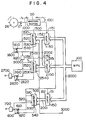
- FIG. 4 An embodiment of the fuel injection control system according to the present invention is shown in Fig. 4.
- numeral 26 designates a pulser having, for example, four protrusions on the outer periphery of a wheel for a four-cylinder engine.
- Numeral 27 designates a sensor for producing a signal indicative of the starting point of the fuel supply period of the rotor of the fuel pump as mentioned above.
- the timing signal 1000 as shown in (A) of Fig. 7a produced from the sensor 27 is shaped into a timing pulse 1001 as shown in (b) of Fig. 7a in the waveform shaping circuit 50.
- the timing pulse 1001 is applied to a data supply control terminal 1151 of a timing latch circuit 1150, a drive terminal 1510 of a counter 1500 and a set terminal 1610 of a flip-flop 1600.
- Data for the delay time in opening of the advance angle-control electromagnetic valve is computed by a microcomputer MPU 100 provided in the control unit 90 of Fig. 3 as mentioned in detail hereinafter is supplied through a data bus 2000 and stored in the latch circuit 1150, which sets the stored time delay data in the counter 1500 upon receipt of the timing pulse 1101 at the data supply control terminal 1151.
- the flip-flop 1600 Upon receipt of the timing pulse 1001 at the set terminal 1610, the flip-flop 1600 is set to make the output signal thereof applied to the reset terminal 1520 of the counter 1520 high level "1" thereby to make the counter ready for counting.
- the counter 1500 starts counting the clock pulses 3000 as shown in (C) of Fig. 7a applied to the clock terminal 1540.
- the counter 1500 Upon counting a number of the clock pulses corresponding to the delay time data, the counter 1500 produces an output signal from the output terminal 1530. This output signal is shaped into a pulse as shown in (F) of Fig.
- the shaped signal is applied as an opening start timing signal for the advance-control electromagnetic valve to the set terminal 2610 of the flip-flop 2000, the data supply control terminal 2151 of the valve open time length latch circuit 2150 and the drive terminal 2510 of the counter 2500.
- the output signal 1530 of the counter 1500 is applied to the reset terminal 1620 of the flip-flop 1600 thereby to change the output signal of the flip-flop 1600 applied to the reset terminal 1520 of the counter 1500, to the low level "0".
- the counter 1500 then stops its counting operation and the content thereof is reset to "0".
- the flip-flop 2600 When the valve opening timing signal derived from the multivibrator 5000 is applied to the set terminal 2610 of the flip-flop 2600, the flip-flop 2600 produces an output signal of high level "1", which makes the counter 2500 ready for counting and at the same time causes the drive circuit 2700 to energize the solenoid of the advance-control electromagnetic valve 15 thereby to open the electromagnetic valve.
- the latch circuit 2150 stores data for the open time interval of the advance control electromagnetic valve computed by the MPU 100 as mentioned later, and upon receipt of the valve opening timing signal at the control terminal 2151, sets the stored data in the counter 2500.
- the counter 2500 starts counting the clock pulses 3000 applied to the clock terminal 2540.
- an output signal is produced from the output terminal 2530.
- This output signal is applied to the reset terminal 2620 of the flip-flop 2600, which changes its output signal to low level "0", so that the drive circuit 2700 closes the advance-control electromagnetic valve.
- the signal applied to the terminal 2520 of the counter 2500 is changed to low level "0" and the counting operation of the counter 2500 is stopped thereby to reset the contents thereof to "0". In this manner, the start and end timings of the open time interval of the advance-control electromagnetic valve are controlled.
- the timing pulse 1001 is applied to the data supply control terminal 151 of the timing data latch circuit 150, the drive terminal 510 of the counter 500 and the set terminal 610 of the flip-flop 600.
- the latch circuit 150 receives through the data bus 2000 and stores data for the open time interval of the injection fuel amount control electromagnetic valve 16 computed by the MPU 100 as mentioned later, and upon receipt of the timing pulse 1001 at the control terminal 151, sets the particular data in the counter 500.
- the counter 500 upon receipt of the timing pulse 1001 at the drive terminal 510, begins to count the clock pulses 3000 applied to the clock terminal 540, and when the count thereof reaches a value corresponding to the set time interval data, produces an output signal from the output terminal 530.
- the flip-flop 600 In response to the timing pulse 1001 applied to the set terminal 610, the flip-flop 600 produces a signal of high level "1", and causes the drive circuit 700 to energize the solenoid of the fuel amount control electromagnetic valve 16 thereby to open the electromagnetic valve 16.
- an output signal of the counter 500 When an output signal of the counter 500 is applied to the reset terminal 620, on the other hand, the output signal is changed to low level "0", so that the drive circuit 700 closes the electromagnetic valve 16.
- the counter 500 stops counting the clock pulses and resets the contents thereof to "0". In this way, the start and end timings of the valve open time length of the injection amount control electromagnetic valve 16 are controlled.
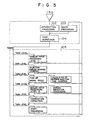
- FIG. 5 A flowchart of a general processing operation by the microcomputer MPU 100 is shown in Fig. 5.
- the microcomputer MPU 100 executes initializing process such as clearing the data in RAM, setting the initial values of the registers of the input-output interface circuit, and storing input data including the cooling water temperature and battery voltage for pre-processing required for engine control. Then, the microcomputer MPU 100 becomes ready for processing the various interruption demands IRQ 101.
- the flowchart for theintializing process is not shown in Fig. 5.
- the interruption processing program 102 receives various interruptions, analyzes the types of interruption, and applies a start demand for staring the required one of the tasks 105 to the task dispatcher 104.
- the types of interruption include an AID conversion interruption (ADC) generated after completion of the A/D conversion of input data, an initial interruption (INTL) generated in synchronism with the engine rotation, and an interval interruption (INTV) generated at a predetermined interval of, say, 10 ms.
- ADC AID conversion interruption
- INTL initial interruption
- INTV interval interruption
- a group of tasks 105 are assigned with task numbers representing the order of priority.
- the task dispatcher 104 determines the task to be processed by the MPU on the basis of the priority order assigned to the respective tasks corresponding to the interruption demands.
- the macro processing program 103 Upon completion of a task processing program determined by the task dispatcher, the macro processing program 103 transmits this information to the task dispatcher 104. On the basis of this information, the task dispatcher 104 determines the next processing task.
- the fuel injection amount is determined at step 201.
- the fuel injection amount is equal to the fuel amount supplied to the second pressure chamber 6 of the injection pump, which is determined by the open time interval of the second electromagnetic valve 15 (hereinafter called the injection time).
- This injection time is computed at step 201 and represented by the number of the clock pulses 3000.
- the injection time may be computed from a map providing a fuel injection amount as a function of the target rotational speed determined from the accelerator position data produced from the acceleration pedal position detector 81 and the actual engine rotational speed produced from the engine rotational speed detector 64.
- a calculating formula is determined on the basis of the control mode to be used such as proportional control for determining the fuel injection amount proportional to the difference signal based on the engine characteristics, differentiation control using the rate in change of the engine rotational speed or integration control using the integration of the difference signals during a predetermined time interval or a combination thereof.
- the calculation formula for determining the fuel injection amount is well known and is not described in detail herein. In this way, the fuel injection time is determined.
- step 202 decides whether or not the computed injection time is shorter than a time corresponding to the maximum allowable injection amount which is calculated and stored on the basis of the current operation condition according to the data stored in the memory. In the case where the comparison at step 202 shows that the computed injection time is longer than the maximum allowable injection time, the injection time is determined to the maximum allowable injection time in step 204. If it is decided at step 202 that the computed injection time is shorter than the maximum allowable injection time, on the other hand, the computed injection time is used as an injection time.
- the determined injection time T 1 is set at step 203.
- the advance T x is determined from the advance angle data for various rotational speeds stored in the memory at step 205 in a similar manner.
- the advance angle is determined by the total fuel supplied to the first pressure chamber 4 and the second pressure chamber 6, and the total fuel is determined by the sum of the valve open time interval of the first electromagnetic valve 15 and that of the second electromagnetic valve 16.
- the advance T x is given as the sum of the open time intervals of the two electromagnetic valves on the assumption that the valve characteristics in relation between the valve open time interval and the injection amount, are the same for the two electromagnetic valves. If the characteristics of the two electromagnetic valves are different from each other, by contrast, it is required to convert the value of the open time interval for one of the electromagnetic valves to an equivalent value of that for the other one.
- the open time T AT of the first electromagnetic valve 15 is calculated as at step 206.
- the fuel supply period T s corresponding to the prevailing engine rotational speed is calculated.
- the open time of the first and second electromagnetic valves 15, 16 are not overlapped.
- the step 208 decides whether or not the electromagnetic valves can be opened without overlap for the calculated open times T, and T AT respectively within the fuel supply period T s .
- margin times a and ⁇ are added to the open times T AT and T, respectively of the first and second electromagnetic valves.
- margin times a and ⁇ are determined taking into consideration the delay of mechanical operation of the electromagnetic valves and the change of the fuel supply period T s which may be caused by the change of the engine rotational speed during the period from the time point of execution of the program of task level 2 to the time point of actual operation of the electromagnetic valves.
- T s is compared with and if is is judged that the electromagnetic valves can be opened without any overlap of open times and the process proceeds to step 210 for calculating the delay To of the opening start time point of the first electromagnetic valve 15 from the opening start time point of the second electromagnetic valve 16 on the basis of as shown in (E) of Fig. 7a.
- step 209 where To is calculated from as shown in (E) of Fig. 7b so that the delay time To of the valve opening start of the first electromagnetic valve 15 is as large as possible to the extent that fuel supply by the first electromagnetic valve 15 is completed within the fuel supply period T s .
- the MPU calculates Tp, T AT and T, at task level 2. These valves are stored in the latch circuits 1150, 2150 and 150 in Fig. 5 respectively.
- Figs. 8a and 8b show an example of the values T x , T, and T AT in the form of linear and polygonal lines as determined from the characteristics of fuel injection amount and advance angle with respect to the engine rotational speed.
- the straight line A in Fig. 8a represents the values T 1 under no load
- the polygonal line B represents the value T 1 under maximum load.
- the polygonal lines C and D represent the values T AT corresponding to the lines A and B, respectively, obtained as the difference between the value T x determined from Fig. 8b and the corresponding value T, determined from the lines A and B.
- the aforementioned embodiment has assumed that the first and second electromagnetic valves have the same characteristics in relation between the valve open time and the fuel injection amount and that the fuel injection amount and the injection advance are determined in the term of open time intervals of the corresponding electromagnetic valve. It should be understood, however, modification can be made within the scope of the present invention such that the ⁇ fuel injection amount and the injection advance may be determined in terms of the amount of fuel supplied to the first and second pressure chambers of the injection pump and the open time of the first and second electromagnetic valves are determined from the. characteristics thereof.
- the above-mentioned calculation of the open time intervals gives equivalent values thereof applicable if the characteristics are the same and hence those calculated equivalent values are subjected to suitable conversion based on the respective characteristics of the valves before being applied thereto.
Landscapes
- Engineering & Computer Science (AREA)
- Chemical & Material Sciences (AREA)
- Combustion & Propulsion (AREA)
- Mechanical Engineering (AREA)
- General Engineering & Computer Science (AREA)
- Electrical Control Of Air Or Fuel Supplied To Internal-Combustion Engine (AREA)
- Fuel-Injection Apparatus (AREA)
Claims (8)


Applications Claiming Priority (2)
| Application Number | Priority Date | Filing Date | Title |
|---|---|---|---|
| JP56058515A JPS582435A (ja) | 1981-04-20 | 1981-04-20 | デイ−ゼル機関用電磁弁駆動タイミング制御装置 |
| JP58515/81 | 1981-04-20 |
Publications (3)
| Publication Number | Publication Date |
|---|---|
| EP0063375A2 EP0063375A2 (fr) | 1982-10-27 |
| EP0063375A3 EP0063375A3 (en) | 1985-08-07 |
| EP0063375B1 true EP0063375B1 (fr) | 1988-10-12 |
Family
ID=13086561
Family Applications (1)
| Application Number | Title | Priority Date | Filing Date |
|---|---|---|---|
| EP82103274A Expired EP0063375B1 (fr) | 1981-04-20 | 1982-04-19 | Système de commande d'injection pour pompe d'injection Diesel commandée par une valve électromagnétique |
Country Status (4)
| Country | Link |
|---|---|
| US (1) | US4401076A (fr) |
| EP (1) | EP0063375B1 (fr) |
| JP (1) | JPS582435A (fr) |
| DE (1) | DE3279107D1 (fr) |
Families Citing this family (16)
| Publication number | Priority date | Publication date | Assignee | Title |
|---|---|---|---|---|
| JPS58150047A (ja) * | 1982-03-03 | 1983-09-06 | Hitachi Ltd | 内燃機関の燃料噴射制御装置 |
| JPS58197466A (ja) * | 1982-05-14 | 1983-11-17 | Hitachi Ltd | 電磁弁制御燃料噴射ポンプ |
| JPS5965523A (ja) * | 1982-10-05 | 1984-04-13 | Nippon Denso Co Ltd | 燃料噴射装置 |
| EP0113553A1 (fr) * | 1982-12-13 | 1984-07-18 | Solex (U.K.) Limited | Appareil de commande électronique de l'alimentation en carburant d'un moteur à combustion interne |
| EP0118038A3 (fr) * | 1983-02-04 | 1986-03-12 | Hitachi, Ltd. | Pompe d'injection de combustible |
| JPS59190436A (ja) * | 1983-04-14 | 1984-10-29 | Yanmar Diesel Engine Co Ltd | 電子燃料噴射装置の制御装置 |
| DE3329800A1 (de) * | 1983-08-18 | 1985-02-28 | Robert Bosch Gmbh, 7000 Stuttgart | Drehzahlregelsystem fuer eine brennkraftmaschine mit selbstzuendung |
| JPS6053661A (ja) * | 1983-09-02 | 1985-03-27 | Hitachi Ltd | デイゼルエンジン用高圧燃料噴射装置 |
| JPS60111045A (ja) * | 1983-11-21 | 1985-06-17 | Hitachi Ltd | デイ−ゼル機関の燃料制御装置 |
| GB8420413D0 (en) * | 1984-08-10 | 1984-09-12 | Lucas Ind Plc | Fuel pumping apparatus |
| JPS6155344A (ja) * | 1984-08-27 | 1986-03-19 | Toyota Motor Corp | デイ−ゼルエンジンの燃料噴射時期制御方法 |
| US4884549A (en) * | 1986-04-21 | 1989-12-05 | Stanadyne Automotive Corp. | Method and apparatus for regulating fuel injection timing and quantity |
| JPH03258951A (ja) * | 1990-03-08 | 1991-11-19 | Toyota Motor Corp | 内燃機関の機関制御装置 |
| US6029628A (en) * | 1998-05-07 | 2000-02-29 | Navistar International Transportation Corp. | Electric-operated fuel injection having de-coupled supply and drain passages to and from an intensifier piston |
| CN103603759B (zh) * | 2013-11-15 | 2015-10-14 | 宁波富莱茵汽车部件有限公司 | 发动机喷油泵的相位差传动系统 |
| JP2017155699A (ja) * | 2016-03-03 | 2017-09-07 | 株式会社クボタ | 多目的車両 |
Citations (1)
| Publication number | Priority date | Publication date | Assignee | Title |
|---|---|---|---|---|
| GB2030222A (en) * | 1978-09-13 | 1980-04-02 | Bendix Corp | Fuel injector for an internal combustion engine for producing fuel injection pulses which have a time-variable flow rate |
Family Cites Families (9)
| Publication number | Priority date | Publication date | Assignee | Title |
|---|---|---|---|---|
| US3107661A (en) * | 1962-07-23 | 1963-10-22 | Cav Ltd | Liquid fuel pumps for internal combustion engines |
| DE1917927A1 (de) * | 1969-04-09 | 1970-10-29 | Bosch Gmbh Robert | Kraftstoffeinspritzpumpe fuer Brennkraftmaschinen |
| DE2011712C3 (de) * | 1970-03-12 | 1979-07-12 | Robert Bosch Gmbh, 7000 Stuttgart | Kraftstoff-Einspritzanlage einer Dieselbrennkraftmaschine |
| US4019478A (en) * | 1972-07-25 | 1977-04-26 | Nippondenso Co., Ltd. | Fuel injection timing control system for internal combustion engine |
| DE2653046A1 (de) * | 1976-11-23 | 1978-05-24 | Bosch Gmbh Robert | Elektronisches regelverfahren und regelsystem zur bestimmung des spritzbeginns bei dieselmotoren |
| JPS6032021B2 (ja) * | 1976-12-26 | 1985-07-25 | 株式会社デンソー | 噴射ポンプ制御装置 |
| GB2041577B (en) * | 1979-01-31 | 1983-04-13 | Lucas Industries Ltd | Fuel system for internal combustion engines |
| JPS5756660A (en) * | 1980-09-22 | 1982-04-05 | Hitachi Ltd | Fuel injection pump |
| US4368705A (en) * | 1981-03-03 | 1983-01-18 | Caterpillar Tractor Co. | Engine control system |
-
1981
- 1981-04-20 JP JP56058515A patent/JPS582435A/ja active Pending
-
1982
- 1982-04-16 US US06/369,028 patent/US4401076A/en not_active Expired - Fee Related
- 1982-04-19 DE DE8282103274T patent/DE3279107D1/de not_active Expired
- 1982-04-19 EP EP82103274A patent/EP0063375B1/fr not_active Expired
Patent Citations (1)
| Publication number | Priority date | Publication date | Assignee | Title |
|---|---|---|---|---|
| GB2030222A (en) * | 1978-09-13 | 1980-04-02 | Bendix Corp | Fuel injector for an internal combustion engine for producing fuel injection pulses which have a time-variable flow rate |
Also Published As
| Publication number | Publication date |
|---|---|
| DE3279107D1 (en) | 1988-11-17 |
| US4401076A (en) | 1983-08-30 |
| EP0063375A3 (en) | 1985-08-07 |
| EP0063375A2 (fr) | 1982-10-27 |
| JPS582435A (ja) | 1983-01-08 |
Similar Documents
| Publication | Publication Date | Title |
|---|---|---|
| US4401076A (en) | Fuel injection control system for electromagnetic valve-controlled fuel injection pump of diesel engine | |
| US4546749A (en) | Fuel injection apparatus | |
| EP0310289B1 (fr) | Système de commande de pompe distributrice d'injection de carburant à valve électromagnétique | |
| US4395905A (en) | Sensor trouble detecting method and apparatus | |
| US4438496A (en) | Electronic fuel injection feedback control method for internal combustion engines | |
| US5201296A (en) | Control system for an internal combustion engine | |
| US4265200A (en) | Method and apparatus for controlling the onset of fuel injection in diesel engines | |
| EP0206517B1 (fr) | Méthode de commande d'alimentation en carburant et appareil d'injection de carburant | |
| US5103792A (en) | Processor based fuel injection control system | |
| US4495915A (en) | Fuel injection device for internal combustion engine | |
| EP0073518B1 (fr) | Appareil de commande du nombre de cylindres en fonctionnement dans un moteur diesel | |
| US4140087A (en) | Method and apparatus for generating fuel injection valve control pulses | |
| EP0202813B1 (fr) | Dispositif de commande d'injection de carburant avec injection forcée durant la période de démarrage | |
| US4475507A (en) | Fuel injection amount control | |
| JPH0536628B2 (fr) | ||
| US4229793A (en) | Method and apparatus for controlling internal combustion engines | |
| US4800861A (en) | Fuel injection system electromagnetic-valve controlled type | |
| US4767288A (en) | Fuel injection pump | |
| US4450816A (en) | Method and apparatus for controlling the fuel injection amount of an internal combustion engine | |
| US4523569A (en) | Liquid fuel pumping apparatus | |
| GB1588935A (en) | Ignition advance system for an internal combustion engine | |
| EP0204220B1 (fr) | Système d'alimentation en carburant au démarrage pour un moteur à combustion comprenant un dispositif d'injection électronique | |
| JPS60135647A (ja) | デイ−ゼルエンジンの燃料噴射装置 | |
| US4590908A (en) | Fuel amount control system in an internal combustion engine | |
| US4566417A (en) | Fuel injection control apparatus for diesel engines |
Legal Events
| Date | Code | Title | Description |
|---|---|---|---|
| PUAI | Public reference made under article 153(3) epc to a published international application that has entered the european phase |
Free format text: ORIGINAL CODE: 0009012 |
|
| AK | Designated contracting states |
Designated state(s): CH DE FR GB IT NL SE |
|
| PUAL | Search report despatched |
Free format text: ORIGINAL CODE: 0009013 |
|
| AK | Designated contracting states |
Designated state(s): CH DE FR GB IT LI NL SE |
|
| 17P | Request for examination filed |
Effective date: 19851003 |
|
| 17Q | First examination report despatched |
Effective date: 19860801 |
|
| R17C | First examination report despatched (corrected) |
Effective date: 19870706 |
|
| GRAA | (expected) grant |
Free format text: ORIGINAL CODE: 0009210 |
|
| RBV | Designated contracting states (corrected) |
Designated state(s): DE FR GB |
|
| AK | Designated contracting states |
Kind code of ref document: B1 Designated state(s): DE FR GB |
|
| REF | Corresponds to: |
Ref document number: 3279107 Country of ref document: DE Date of ref document: 19881117 |
|
| ET | Fr: translation filed | ||
| PLBE | No opposition filed within time limit |
Free format text: ORIGINAL CODE: 0009261 |
|
| STAA | Information on the status of an ep patent application or granted ep patent |
Free format text: STATUS: NO OPPOSITION FILED WITHIN TIME LIMIT |
|
| 26N | No opposition filed | ||
| PGFP | Annual fee paid to national office [announced via postgrant information from national office to epo] |
Ref country code: FR Payment date: 19910314 Year of fee payment: 10 |
|
| PGFP | Annual fee paid to national office [announced via postgrant information from national office to epo] |
Ref country code: GB Payment date: 19910409 Year of fee payment: 10 |
|
| PGFP | Annual fee paid to national office [announced via postgrant information from national office to epo] |
Ref country code: DE Payment date: 19910524 Year of fee payment: 10 |
|
| PG25 | Lapsed in a contracting state [announced via postgrant information from national office to epo] |
Ref country code: GB Effective date: 19920419 |
|
| GBPC | Gb: european patent ceased through non-payment of renewal fee | ||
| PG25 | Lapsed in a contracting state [announced via postgrant information from national office to epo] |
Ref country code: FR Effective date: 19921230 |
|
| PG25 | Lapsed in a contracting state [announced via postgrant information from national office to epo] |
Ref country code: DE Effective date: 19930101 |
|
| REG | Reference to a national code |
Ref country code: FR Ref legal event code: ST |