EP0063400B1 - Verfahren und Apparat zum Überführen von gegärten Teigstücken auf ein Ofenband - Google Patents
Verfahren und Apparat zum Überführen von gegärten Teigstücken auf ein Ofenband Download PDFInfo
- Publication number
- EP0063400B1 EP0063400B1 EP82200462A EP82200462A EP0063400B1 EP 0063400 B1 EP0063400 B1 EP 0063400B1 EP 82200462 A EP82200462 A EP 82200462A EP 82200462 A EP82200462 A EP 82200462A EP 0063400 B1 EP0063400 B1 EP 0063400B1
- Authority
- EP
- European Patent Office
- Prior art keywords
- underlay
- oven
- transfer belt
- transport
- batch
- Prior art date
- Legal status (The legal status is an assumption and is not a legal conclusion. Google has not performed a legal analysis and makes no representation as to the accuracy of the status listed.)
- Expired
Links
- 238000000034 method Methods 0.000 title claims description 7
- 238000000151 deposition Methods 0.000 claims description 4
- 230000000977 initiatory effect Effects 0.000 claims description 3
- 235000008429 bread Nutrition 0.000 description 1
- 238000006073 displacement reaction Methods 0.000 description 1
- 230000000694 effects Effects 0.000 description 1
- 230000000284 resting effect Effects 0.000 description 1
- 239000000725 suspension Substances 0.000 description 1
Images



Classifications
-
- A—HUMAN NECESSITIES
- A21—BAKING; EDIBLE DOUGHS
- A21B—BAKERS' OVENS; MACHINES OR EQUIPMENT FOR BAKING
- A21B3/00—Parts or accessories of ovens
- A21B3/07—Charging or discharging ovens
-
- A—HUMAN NECESSITIES
- A21—BAKING; EDIBLE DOUGHS
- A21C—MACHINES OR EQUIPMENT FOR MAKING OR PROCESSING DOUGHS; HANDLING BAKED ARTICLES MADE FROM DOUGH
- A21C9/00—Other apparatus for handling dough or dough pieces
- A21C9/08—Depositing, arranging and conveying apparatus for handling pieces, e.g. sheets of dough
- A21C9/081—Charging of baking tins or forms with dough
Definitions
- the invention relates to a method of transferring proofed doughpieces from a proofer transport to a continuously moving oven underlay, in which a doughpiece batch from the proofer transport is picked up by a transfer belt in a pick-up zone by driving said transfer belt to pull said batch over a leading portion of said belt, said transfer belt, controlled by a sensor arranged adjacent the oven underlay, is advanced towards the underlay and the batch lying on the transfer belt is deposited on the oven underlay in a delivery zone by driving the transfer belt in an unloading sense and withdrawing the belt simultaneously over the oven underlay surface.
- the known method is not fit for solving the problem of transfer of doughpieces from a proofer transport to a continuously moving oven underlay, wherein the supply rate of the doughpieces is determined by the speed of the proofer transport, while the delivery rate of the doughpieces is determined by the, different, speed of the oven underlay.
- substantial spaces occur on the oven underlay, i.e. the filling of the oven is not optimal. It is the object of the invention to eliminate this drawback.
- the transfer belt signalled by the batch already present on the oven underlay, is advanced from a position on the other side of the proofer transport, over the proofer transport towards the oven underlay and concurrently therewith, thereby picks up a batch from the proofer transport, said transfer belt advance is continued over the oven underlay to catch up with the previous batch; the batch is deposited on the oven underlay consecutively to the previous batch on driving the transfer belt in supplying sense with simultaneous withdrawal of the transfer belt in a direction opposite to the transport direction of the oven underlay and so depositing the doughpiece batch over the same leading portion, over which the batch has been picked up before, which withdrawal of the transfer belt is continued until the starting position on the said other side of the proofer transport is reattained.
- the transfer belt itself is only driven in an amount sufficient to pick up a batch of doughpieces from the proofer transport and afterwards is driven in the reverse direction to deliver the batch on the oven underlay and since the bridging of the distance between the proofer transport and the depositing area on the oven underlay is effected by moving the entire transfer belt and not by driving the belt itself, any difference in supply rate and delivery rate is easily compensated without the need of driving the transfer belt carrying a batch of doughpieces at a high speed. Therefore different oven underlay speeds can be simply taken into account, which are determined by the baking times required for the different baking products. Independently of the underlay speed there is thus ensured an optimal occupation of the oven.
- the invention provides an apparatus having a reliable operation through a simple manner of driving.
- the apparatus according to the invention for transferring proofed doughpieces from a proofer transport to a continuously moving oven underlay provided with a single transfer belt drivable in two directions and furthermore being entirely translatable between a pick-up zone at the proofer transport to a delivery zone above the oven underlay and comprising a sensor, such as a photocell, for detecting the position of a preceding dough piece batch on the oven underlay and for initiating loading and advance of the transfer belt to the delivery zone above the underlay (US-A-3,603,271) is characterized by said transfer belt having a leading portion over which a batch is picked up as well as deposited and by a further sensor at the pick-up zone for doughpiece batches supplied by the proofer transport for positioning the doughpiece batches in such a way that, seen in the direction of the oven transport, the leading doughpieces of the batch on the transfer belt are always loaded at the same position relative to said loading edge.
- a sensor such as a photocell
- the leading doughpieces of each batch to be deposited on the oven underlay are always in the same position at the moment the batch is loaded onto the transfer belt. It is thus ensured that during the pick-up of the doughpiece batches, these always come to lie on a previously selected place on the transfer belt and during the delivery of the doughpiece batches on the oven underlay, these properly link up with the preceding batch.
- a simple control of the transfer belt is provided by the invention wherein the drive of the transfer belt is effected by means of a rack, said belt being movable along said rack for driving the belt, said rack being translatable over the proofer transport towards the oven underlay and back to a starting position behind the proofer transport.
- the rack and the belt are being held stationary in a position behind the proofer transport and after initiating by the sensors the transfer belt is drawn along the rack thereby picking up doughpieces from the proofer transport.
- the rack After the loading of the transfer belt the rack, so far stationary, is translated together with the transfer belt to the delivery position above the oven underlay and arrived at that position the rack is again arrested, while the transfer belt is displaced reversally along the rack for driving the belt in supplying sense and subsequently the assembly of rack and transfer belt is again translated towards the starting position.
- the transfer belt according to the invention can be driven in loading and unloading sense over one single leading end edge. This means that only a part of the length of the endless belt has a doughpiece-carrying function.
- a drawback of relatively short and wide endless conveyor belts namely difficult centering thereof, is eliminated by replacing according to the invention the non-carrying portion of the conveyor belt by a plurality of chains guided over chain wheels.
- the chain wheels are mounted on a common shaft which also carries a gear which coacts with the rack.
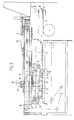
- proofed doughpieces 1 are supplied on pallets 2 from a proofer (not shown).
- the proofer transport is indicated by 3.
- Empty pallets are discharged on a conveyor 4.
- the doughpieces 1 are to be transferred to an oven conveyor belt (oven underlay) 5 which moves according to arrow T.
- the transfer is effected by means of a. t ransfer belt 6 of the nibbling belt type, i.e. provided with a flat self-supporting edge or nose 7 which can be brought exactly above the bearing area of a pallet 2 so that through relative movement of the nose 7 and the pallet 2 and simultaneous drive of the belt in pickup sense, doughpieces 1 can be drawn on the belt 6.
- a. t ransfer belt 6 of the nibbling belt type i.e. provided with a flat self-supporting edge or nose 7 which can be brought exactly above the bearing area of a pallet 2 so that through relative movement of the nose 7 and the pallet 2 and simultaneous drive of the belt in pickup sense, doughpieces 1 can be drawn on the belt 6.
- the belt is composed of a carrying portion formed by an underlay 8 and a non-carrying portion in which extend chains 10 applied over chain wheels 9.
- the chain wheels 9 are fixed on a shaft 11 on which is also secured a pinion 12 which is in engagement with a rack 13.
- the rack 13 is movable over a rod 14. By displacement of the pinion over the rack 13, the chain wheels 9 are rotated and thus belt 8, 10 is driven, while the underlay 8 is drawn about a flat frame 15 (see Fig. 2) for drawing (nibbling) doughpieces 1 on the underlay 8 or vice versa for unloading doughpieces.
- phase a transfer belt 6 and rack 13 are in the starting position, on the proofer transport 3 there is provided a pallet 2 with doughpieces 1 and on the oven underlay can be seen a preceding batch L which has not yet passed a photocell 16.
- phase b the batch L has just passed the photocell 16 so that the loading of the transfer belt 6 is initiated.
- the transfer belt 6 moves relative to the rack 13 so that the belt is driven in doughpieces-pickup sense and simultaneously the nose 7 moves over the pallet 2.
- the rack 13 is stationary.
- Phase c shows the situation in which the doughpieces 1 have been taken over from the pallet 2 on the belt 6. In this phase the rack 13 is still stationary in the starting position of phase a.
- phase d belt 6 and rack 13 in the relative position of phase c have been jointly moved to a position above the belt 5 wherein the nose 7 is present just behind the preceding batch L.
- the empty pallet 2 has been pushed on the discharge conveyor 4.
- the doughpieces 1 in phase e are deposited on the oven underlay 5 successively behind the preceding batch L by rearwardly displacing the belt 6 along the stationary rack 13 until phase fis attained, from which belt 6 and rack 13 are both moved rearwardly to the starting position of phase a, after which a new cycle can be initiated with the supply of a loaded pallet 2.
- the transfer belt 6 is mounted between side plates 17 slidable over rods 18 by means of drive chains 19.
- the rack 13 is slidable over the rods 14 by means of a pawl drive an element 20 of which is shown.
- an auxiliary roller 21 can contribute to a reliable guide of small doughpieces on and off the belt 6.
- the auxiliary roller 21 is mounted parallel to the nose 7 in arms 22 the position of which can be influenced by suspension from rods 23, rollers 24 and cam tracks 25 a portion 26 of which can be swivelled away upwardly. Through a lever 24' the relative position of the auxiliary roller 21 relative to the cam tracks 25 can be determined.
- the transfer belt 6 with the nose 7 can be steered in different height positions, on the one hand for bridging differences in height between pickup and delivery level of doughpieces and on the other hand to have the possibility of dropping at such a high level that the doughpieces are deposited upside-down.
- the differences in height of the nose 7 are indicated in Fig. 3 at the righthand side in the Figure.
- rods 27 and rollers 28 riding on the cam tracks 25, 26.
- Fig. 3 shows besides the photocell 16 at the delivery position for doughpieces 1 on the oven underlay 5, also photocells 29 and 30 for controlling the position of the pallets 2 in such a way that a doughpieces batch resting thereon is accurately positioned prior to the pickup by the transfer belt 6 so that also the position of the batch on the transfer belt 6 and the depositing position on the underlay 5 is fixed and furthermore also the discharge of the empty pallets is automatically controlled.
Landscapes
- Life Sciences & Earth Sciences (AREA)
- Engineering & Computer Science (AREA)
- Food Science & Technology (AREA)
- Manufacturing And Processing Devices For Dough (AREA)
- Intermediate Stations On Conveyors (AREA)
- Processing And Handling Of Plastics And Other Materials For Molding In General (AREA)
- Heating, Cooling, Or Curing Plastics Or The Like In General (AREA)
Claims (5)
dadurch gekennzeichnet, daß gemäß einem Signal von dem bereits aud der Ofenunterlage (5) befindlichen Schub (L) das Überführungsband (6) aus einer Stellung auf der anderen Seite des Gärtransports (3) über den Gärtransport (3) auf die Ofenunterlage (5) zu bewegt wird und gleichzeitig einen Schub (1) von dem Gärtransport (3) aufnimmt, wobei die Vorwärtsbewegung des Überführungsbandes (6) über die Ofenunterlage (5) fortgesetzt wird, um den vorhergehenden Schub (L) einzuholen;
daß der Schub (1) auf der Ofenunterlage (5) an den vorhergehenden Schub (L) anschließend abgelegt wird, wobei das Überführungsband im Zuführungssinn bei gleichzeitigem Zurückziehen des Überführungsbandes (6) in eine zur Transportrichtung des Ofenbandes (5) entgegengesetzte Richtung angetrieben wird und so der Schub (1) von Teigstücken über denselben Vorderabschnitt (7) abgelegt wird, über den der Schub (1) zuvor aufgenommen wurde, und wobei das Zurückziehen des Überführungsbandes fortgesetzt wird, bis die Anfangsstellung auf der anderen Seite des Gärtransports (3) wieder erreicht ist.
Priority Applications (1)
| Application Number | Priority Date | Filing Date | Title |
|---|---|---|---|
| AT82200462T ATE15433T1 (de) | 1981-04-16 | 1982-04-15 | Verfahren und apparat zum ueberfuehren von gegaerten teigstuecken auf ein ofenband. |
Applications Claiming Priority (2)
| Application Number | Priority Date | Filing Date | Title |
|---|---|---|---|
| NL8101904A NL8101904A (nl) | 1981-04-16 | 1981-04-16 | Overzetinrichting. |
| NL8101904 | 1981-04-16 |
Publications (2)
| Publication Number | Publication Date |
|---|---|
| EP0063400A1 EP0063400A1 (de) | 1982-10-27 |
| EP0063400B1 true EP0063400B1 (de) | 1985-09-11 |
Family
ID=19837375
Family Applications (1)
| Application Number | Title | Priority Date | Filing Date |
|---|---|---|---|
| EP82200462A Expired EP0063400B1 (de) | 1981-04-16 | 1982-04-15 | Verfahren und Apparat zum Überführen von gegärten Teigstücken auf ein Ofenband |
Country Status (6)
| Country | Link |
|---|---|
| EP (1) | EP0063400B1 (de) |
| JP (1) | JPH0376891B2 (de) |
| AT (1) | ATE15433T1 (de) |
| CA (1) | CA1190437A (de) |
| DE (1) | DE3266127D1 (de) |
| NL (1) | NL8101904A (de) |
Cited By (1)
| Publication number | Priority date | Publication date | Assignee | Title |
|---|---|---|---|---|
| DE102011109967A1 (de) | 2011-08-02 | 2013-02-07 | Multivac Sepp Haggenmüller Gmbh & Co. Kg | Greifersystem |
Families Citing this family (17)
| Publication number | Priority date | Publication date | Assignee | Title |
|---|---|---|---|---|
| FI860352L (fi) * | 1986-01-24 | 1987-07-25 | Jukka Joukainen | Foerfarande foer automatisk transport av produkter i en bagerilinje som innefattar en ugn med fast rost. |
| US4668524A (en) * | 1986-01-29 | 1987-05-26 | Lawrence Equipment Inc. | Dough ball conveyor loader apparatus and method |
| GB2188601B (en) * | 1986-02-25 | 1990-07-11 | Molins Plc | Conveyor system for rod-like articles |
| US5190428A (en) * | 1986-02-25 | 1993-03-02 | Molins Machine Company, Inc. | Conveyor system for rod-like articles |
| JPH01150619A (ja) * | 1987-12-07 | 1989-06-13 | Nippon Ham Kk | 移載用すくい取り機構 |
| NL8801525A (nl) * | 1988-06-15 | 1990-01-02 | Werner & Pfleiderer Haton Bv | Inrichting voor het overbrengen van voorwerpen vanaf een afleverinrichting naar een opneeminrichting. |
| DE4214484A1 (de) * | 1992-05-07 | 1993-11-11 | Werner & Pfleiderer | Verfahren und Vorrichtung zum Überführen von gegärten Teiglingen |
| NL9301112A (nl) * | 1993-06-25 | 1995-01-16 | Ambaco B V | Werkwijze en inrichting voor het overbrengen van deegprodukten vanaf de plaat waarop ze zijn gevormd op een transportband. |
| NL1004935C2 (nl) * | 1997-01-06 | 1998-07-08 | Kaak Johan H B | Inrichting voor het toevoeren van deegstukken aan deegbakken van een voorrijskast. |
| JP4941866B2 (ja) * | 2006-01-30 | 2012-05-30 | 古川機工株式会社 | 移載方法及びその装置 |
| GB0603002D0 (en) | 2006-02-15 | 2006-03-29 | Aew Delford Group Ltd | Improved pick and place handling device |
| JP4889514B2 (ja) * | 2007-01-29 | 2012-03-07 | 古川機工株式会社 | 物品のせ降ろし方法と物品のせ降ろし装置 |
| JP4902397B2 (ja) * | 2007-03-12 | 2012-03-21 | 古川機工株式会社 | 物品自動移動装置 |
| FR2978436B1 (fr) * | 2011-07-29 | 2015-12-04 | Vendee Concept | Installation pour la manutention de produits, en particulier de tranches de denrees alimentaires |
| JP6742944B2 (ja) * | 2017-04-21 | 2020-08-19 | 株式会社ケイズベルテック | 移載装置 |
| CN107324006B (zh) * | 2017-08-16 | 2022-10-21 | 吕明芳 | 自动落板叠合传输装置 |
| JP7105676B2 (ja) * | 2018-11-09 | 2022-07-25 | Pacraft株式会社 | 物品搬送システム |
Family Cites Families (2)
| Publication number | Priority date | Publication date | Assignee | Title |
|---|---|---|---|---|
| US3603271A (en) * | 1968-02-09 | 1971-09-07 | Fr Windler Kg | Equipment for transferring pieces of dough |
| GB1273510A (en) * | 1969-02-18 | 1972-05-10 | Antonio Dominici | Distributing device |
-
1981
- 1981-04-16 NL NL8101904A patent/NL8101904A/nl not_active Application Discontinuation
-
1982
- 1982-04-15 CA CA000401080A patent/CA1190437A/en not_active Expired
- 1982-04-15 EP EP82200462A patent/EP0063400B1/de not_active Expired
- 1982-04-15 DE DE8282200462T patent/DE3266127D1/de not_active Expired
- 1982-04-15 AT AT82200462T patent/ATE15433T1/de not_active IP Right Cessation
- 1982-04-16 JP JP57063800A patent/JPH0376891B2/ja not_active Expired - Lifetime
Cited By (3)
| Publication number | Priority date | Publication date | Assignee | Title |
|---|---|---|---|---|
| DE102011109967A1 (de) | 2011-08-02 | 2013-02-07 | Multivac Sepp Haggenmüller Gmbh & Co. Kg | Greifersystem |
| US8628131B2 (en) | 2011-08-02 | 2014-01-14 | Multivac Sepp Haggenmueller Gmbh & Co. Kg | Product gripper system |
| DE102011109967B4 (de) * | 2011-08-02 | 2016-12-01 | Multivac Sepp Haggenmüller Se & Co. Kg | Greifersystem |
Also Published As
| Publication number | Publication date |
|---|---|
| EP0063400A1 (de) | 1982-10-27 |
| DE3266127D1 (en) | 1985-10-17 |
| JPH0376891B2 (en) | 1991-12-06 |
| CA1190437A (en) | 1985-07-16 |
| NL8101904A (nl) | 1982-11-16 |
| JPS57181631A (en) | 1982-11-09 |
| ATE15433T1 (de) | 1985-09-15 |
Similar Documents
| Publication | Publication Date | Title |
|---|---|---|
| EP0063400A1 (de) | Verfahren und Apparat zum Überführen von gegärten Teigstücken auf ein Ofenband | |
| EP0659664B1 (de) | Vorrichtung und Verfahren zum Palettieren von instabilen Gegenständen | |
| US3343504A (en) | Apparatus for placing pastries in pairs one on top of the other | |
| US3737021A (en) | Device for transferring groups of rods from a rake-type cooling bed to a series of rollers for charging a cooling bed cold shears | |
| US4306646A (en) | Conveyor apparatus | |
| US4067458A (en) | Apparatus for the unstacking and transportation of blanks | |
| US5044876A (en) | Apparatus for forming and transferring groups of articles | |
| US3783772A (en) | Sandwich machine | |
| US6220424B1 (en) | Method and apparatus for transferring items from a conveyor | |
| US5096041A (en) | Method and apparatus for receiving and delivering articles with differing motion characteristics | |
| GB2060571A (en) | Device for stacking flat articles such as box blanks | |
| US4274532A (en) | Can handling system | |
| US7581637B2 (en) | Feeding device for a packaging machine | |
| US5687454A (en) | Coiler can transport system between two drawing frames | |
| US4090618A (en) | Device for inserting spacing strips between boards to be stacked | |
| US4503965A (en) | Apparatus for handling rod-like articles | |
| JPH0129605B2 (de) | ||
| EP0659665A1 (de) | Vorrichtung zum kontinuierlichen Zuführen von Stückgutteilen von einem Hauptförderer zu Zwischenabführkanälen, Schräg angestellt in Bezug auf den Hauptförderer | |
| US3637093A (en) | Palleting apparatus | |
| USRE31945E (en) | Conveyor apparatus | |
| US4201506A (en) | Lumber-stacking method and apparatus | |
| GB2062567A (en) | Apparatus for handling rod-like articles | |
| EP0066907B1 (de) | Wagen zum automatischen Beschicken von Brotlaiben auf Trägern | |
| US4059261A (en) | Machine and method for successively feeding stacked blanks | |
| JP3591891B2 (ja) | ネスティング対象コンテナの搬送装置 |
Legal Events
| Date | Code | Title | Description |
|---|---|---|---|
| PUAI | Public reference made under article 153(3) epc to a published international application that has entered the european phase |
Free format text: ORIGINAL CODE: 0009012 |
|
| AK | Designated contracting states |
Designated state(s): AT BE CH DE GB IT NL SE |
|
| 17P | Request for examination filed |
Effective date: 19821018 |
|
| ITF | It: translation for a ep patent filed | ||
| GRAA | (expected) grant |
Free format text: ORIGINAL CODE: 0009210 |
|
| AK | Designated contracting states |
Designated state(s): AT BE CH DE GB IT LI NL SE |
|
| REF | Corresponds to: |
Ref document number: 15433 Country of ref document: AT Date of ref document: 19850915 Kind code of ref document: T |
|
| REF | Corresponds to: |
Ref document number: 3266127 Country of ref document: DE Date of ref document: 19851017 |
|
| PLBE | No opposition filed within time limit |
Free format text: ORIGINAL CODE: 0009261 |
|
| STAA | Information on the status of an ep patent application or granted ep patent |
Free format text: STATUS: NO OPPOSITION FILED WITHIN TIME LIMIT |
|
| 26N | No opposition filed | ||
| ITTA | It: last paid annual fee | ||
| PGFP | Annual fee paid to national office [announced via postgrant information from national office to epo] |
Ref country code: SE Payment date: 19930416 Year of fee payment: 12 |
|
| PGFP | Annual fee paid to national office [announced via postgrant information from national office to epo] |
Ref country code: CH Payment date: 19930422 Year of fee payment: 12 |
|
| PGFP | Annual fee paid to national office [announced via postgrant information from national office to epo] |
Ref country code: DE Payment date: 19930427 Year of fee payment: 12 |
|
| PGFP | Annual fee paid to national office [announced via postgrant information from national office to epo] |
Ref country code: AT Payment date: 19930428 Year of fee payment: 12 |
|
| PGFP | Annual fee paid to national office [announced via postgrant information from national office to epo] |
Ref country code: NL Payment date: 19930430 Year of fee payment: 12 |
|
| PGFP | Annual fee paid to national office [announced via postgrant information from national office to epo] |
Ref country code: BE Payment date: 19930507 Year of fee payment: 12 |
|
| PG25 | Lapsed in a contracting state [announced via postgrant information from national office to epo] |
Ref country code: AT Effective date: 19940415 |
|
| PG25 | Lapsed in a contracting state [announced via postgrant information from national office to epo] |
Ref country code: SE Effective date: 19940416 |
|
| PG25 | Lapsed in a contracting state [announced via postgrant information from national office to epo] |
Ref country code: LI Effective date: 19940430 Ref country code: CH Effective date: 19940430 Ref country code: BE Effective date: 19940430 |
|
| PGFP | Annual fee paid to national office [announced via postgrant information from national office to epo] |
Ref country code: GB Payment date: 19940506 Year of fee payment: 13 |
|
| BERE | Be: lapsed |
Owner name: GEBR. VAN CAPELLEVEEN B.V. Effective date: 19940430 |
|
| PG25 | Lapsed in a contracting state [announced via postgrant information from national office to epo] |
Ref country code: NL Effective date: 19941101 |
|
| NLV4 | Nl: lapsed or anulled due to non-payment of the annual fee | ||
| REG | Reference to a national code |
Ref country code: CH Ref legal event code: PL |
|
| PG25 | Lapsed in a contracting state [announced via postgrant information from national office to epo] |
Ref country code: DE Effective date: 19950103 |
|
| EUG | Se: european patent has lapsed |
Ref document number: 82200462.8 Effective date: 19941110 |
|
| PG25 | Lapsed in a contracting state [announced via postgrant information from national office to epo] |
Ref country code: GB Effective date: 19950415 |
|
| GBPC | Gb: european patent ceased through non-payment of renewal fee |
Effective date: 19950415 |