EP0063488B1 - Ankerhalterung - Google Patents
Ankerhalterung Download PDFInfo
- Publication number
- EP0063488B1 EP0063488B1 EP19820301985 EP82301985A EP0063488B1 EP 0063488 B1 EP0063488 B1 EP 0063488B1 EP 19820301985 EP19820301985 EP 19820301985 EP 82301985 A EP82301985 A EP 82301985A EP 0063488 B1 EP0063488 B1 EP 0063488B1
- Authority
- EP
- European Patent Office
- Prior art keywords
- armature
- yoke
- spring
- portions
- wire
- Prior art date
- Legal status (The legal status is an assumption and is not a legal conclusion. Google has not performed a legal analysis and makes no representation as to the accuracy of the status listed.)
- Expired
Links
Images


Classifications
-
- H—ELECTRICITY
- H01—ELECTRIC ELEMENTS
- H01F—MAGNETS; INDUCTANCES; TRANSFORMERS; SELECTION OF MATERIALS FOR THEIR MAGNETIC PROPERTIES
- H01F7/00—Magnets
- H01F7/06—Electromagnets; Actuators including electromagnets
- H01F7/08—Electromagnets; Actuators including electromagnets with armatures
-
- H—ELECTRICITY
- H01—ELECTRIC ELEMENTS
- H01H—ELECTRIC SWITCHES; RELAYS; SELECTORS; EMERGENCY PROTECTIVE DEVICES
- H01H50/00—Details of electromagnetic relays
- H01H50/02—Bases; Casings; Covers
- H01H50/04—Mounting complete relay or separate parts of relay on a base or inside a case
- H01H50/041—Details concerning assembly of relays
- H01H50/042—Different parts are assembled by insertion without extra mounting facilities like screws, in an isolated mounting part, e.g. stack mounting on a coil-support
-
- H—ELECTRICITY
- H01—ELECTRIC ELEMENTS
- H01H—ELECTRIC SWITCHES; RELAYS; SELECTORS; EMERGENCY PROTECTIVE DEVICES
- H01H50/00—Details of electromagnetic relays
- H01H50/16—Magnetic circuit arrangements
- H01H50/18—Movable parts of magnetic circuits, e.g. armature
- H01H50/24—Parts rotatable or rockable outside coil
- H01H50/26—Parts movable about a knife edge
-
- H—ELECTRICITY
- H01—ELECTRIC ELEMENTS
- H01H—ELECTRIC SWITCHES; RELAYS; SELECTORS; EMERGENCY PROTECTIVE DEVICES
- H01H50/00—Details of electromagnetic relays
- H01H50/64—Driving arrangements between movable part of magnetic circuit and contact
- H01H50/641—Driving arrangements between movable part of magnetic circuit and contact intermediate part performing a rectilinear movement
- H01H50/642—Driving arrangements between movable part of magnetic circuit and contact intermediate part performing a rectilinear movement intermediate part being generally a slide plate, e.g. a card
Definitions
- the present invention relates to an armature holding structure in an electromagnetic relay comprising an electromagnet having a core, a coil and a yoke, an armature and a wire hinge-spring coupled to both the yoke and the armature and pivoting the armature at the end of the yoke.
- an armature holding structure is used in order to support an armature rotatably on one end portion of the yoke of the electromagnet.
- FIGs. 1A, 1B, 2A and 2B Examples of the prior art armature holding structure in an electromagnetic relay are illustrated in Figs. 1A, 1B, 2A and 2B.
- the armature 2' having a rectangular aperture 23' and a groove 22', rides on one end of the yoke 13', having a rectangular aperture 132', of the electromagnetic 1'.
- a hinge plate-spring 3' having the ends partly rolled under (Figs. 1A, 1B) or a hinge plate-spring 3" having several bent portions (Figs.
- Such hinge plate-spring 3' or 3" is manufactured by the process of punching a planar plate having a predetermined size from a sheet and then working such punched planar plate to give either a shape in which the ends are partly rolled under (Figs. 1A, 1B) or a shape having several bent portions (Figs. 2A, 2B).
- the process of attaching the hinge plate-spring 3' or 3" to the groove 22' and the rectangular aperture 132' requires specially skillful work, without which the preliminary stored resilient force of the hinge plate-spring 3' or 3" are likely to be departed from so that uniformity of the operating characteristics of the produced electromagnetic relays cannot be achieved.
- the hinge plate-spring 3' or 3" is manufactured by punching a planar plate from a sheet having a large size in the longitudinal direction, which sheet has been manufactured by the rolling process, the degree of utilization of the sheet as a material for such punched planar plate cannot be increased. This is because the punching of the planar plate should be carried out so that the longitudinal direction of the hinge plate-spring coincides with the longitudinal direction of the sheet in order to ensure the metallurgical strength of the hinge plate-spring.
- Figs. 2A, 2B The structure of Figs. 2A, 2B is disclosed in Japanese utility model application laid-open No. 53-89541.
- GB-A-1224151 describes a structure for a small electromagnetic relay in which the armature is a knee piece pivoting on the end of the yoke and retained by a generally M-shaped wire return spring lying between the yoke and the winding, which is encapsulated, and lodging between two projections projecting from the yoke, the end of the two sides of the M being bent inwardly through more than 90° to engage in depressions in the region of the outer angle of the knee piece.
- This arrangement of the armature return and retaining spring which acts as a tension spring and is arranged freely between the yoke and the encapsulated winding so as to balance the forces, requires that the winding be enclosed.
- the projections, for example studs, necessary on the yoke add to the cost and processing required to produce the structure. Further, the M shape of the wire spring makes it difficult to- install.
- DE-U-1940185 describes a structure in which the armature is formed of two bent plates, one providing a pair of spaced actuating arms and the other a stop member which is disposed between the two actuating arms and arranged so as to limit rotation of the armature away from the core of the electromagnet by coming into contact with the outer surface of the yoke.
- a wire spring has each end caught in a respective recess in the inner surface of the yoke relative to the winding, and a mid-portion lodged against a projection formed on the armature plate providing the stop member.
- the spring is substantially in the form of two hooks connected at the ends of the longer limbs by the mid-portion which is straight and is parallel to the pivot axis of the armature on the yoke, the spring holding the armature against one end of the yoke.
- the ends of the spring are bent to extend perpendicularly to the planes of the two hook portions and extend towards one another.
- the spring is thus shaped to cooperate with the two part structure of the armature, and is difficult to install.
- the structure of the armature is relatively complex, and therefore more costly and time consuming to manufacture, and furthermore is liable to provide a higher reluctance.
- an armature holding structure of the kind defined hereinbefore is characterised in that one end of the wire spring is held in a hole in the yoke, and the other end of the wire spring is held in a recess in the armature, in that the intermediate portion of the wire spring passes through a groove in a member of the relay, along the side surfaces of the yoke and the armature and over the outer surface of the armature, in that the relay includes a base block to which the yoke is fixed, the base block having a shelf formed perpendicular thereto which projects into the space between the yoke and the coil, and in that the said member is the said shelf or the yoke.
- the wire spring consists of first, second third, fourth and fifth portions, each of the first to fifth portions being arranged to form a predetermined angle with respect to the adjacent portion, the first and the fifth portions being adapted to be inserted respectively into the hole in the yoke and the recess in the armature, and the second and the fourth portions lying in the same plane.
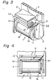
- FIG. 3 An electromagnetic relay using a wire hinge-spring for holding an armature in accordance with an embodiment of the present invention is illustrated in a perspective view in Fig. 3.
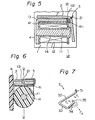
- the detailed structures of the device of Fig. 3 are illustrated in Figs. 4, 5, 6 and 7.
- the important portion of the device of Fig. 3 comprises an electromagnet 1 consisting of a core 11, a coil 12, a bobbin 14, a yoke 13, an armature 2, a wire hinge-spring 3 and a base block 4 having a shelf 41 projecting from the base block 4.
- other elements of the electromagnetic relay are provided, such as a card, a movable contact spring, a fixed contact spring and a restoring spring to form a complete assembly of the elements of the electromagnetic relay.
- the motion of the armature 2 causes, via the card, the movement of the movable contact spring to cause the movable contact to come in contact with the fixed contact.
- Such complete assembly of the elements is encased in a housing consisting of the base block 4 and a cover (not shown).
- the yoke 13 of the electromagnet 1 is fixed to the base block 4.
- the shelf 41 is provided for determining the position of the electromagnet 1 with respect to the base block 4.
- the armature 2 is pivoted at the inner corner thereof on the edge of the yoke 13.
- the wire hinge-spring 3 is provided to combine the armature 2 and the end portion of the yoke 13.
- the wire hinge-spring 3 consists of a first 31, second 32, third 33, fourth 34 and fifth portion 35.
- the first portion 31 is held in a hole 131 in the yoke 13.
- the second portion 32 is held in a groove 411 in the shelf 41.
- the third portion 33 lies on the side surfaces of the shelf 41, the yoke 13 and the armature 2.
- the fourth portion 34 lies along the ridge 21 of the armature 2.
- the fifth portion 35 is held in a recess 22 in the ridge 21 of the armature 2.
- the wire hinge-spring 3 is made of, for example, stainless steel.
- the shape of the wire . hinge-spring 3 is as shown in Fig. 7, wherein the second portion 32 and the fifth portion 35 lie in the same plane.
- the resilient force F which is exerted in the direction parallel to the direction of the third portion 33, causes the fourth and the fifth portions 34, 35 to be pressed inwardly toward the second portion 32.
- This resilient force F acts as a combining force between the ridge 21 of the armature 2 and the end portion of the yoke 13.
- the armature 2 is mounted at the inner corner thereof on the edge of the yoke 13. Then, the first and the second portions 31, 32 are inserted into the groove 411 and the shelf 41 until the first portion 31 is inserted into the hole 131 in the yoke 13.
- the third portion 33 is moved clockwise along the side surfaces of the shelf 41, the yoke 13 and the armature 2, with the fourth and the fifth portions 34, 35 being simultaneously pressed outwardly by the force F 2 , thereby enabling the fourth and the fifth portions 34, 35 to go over the ridge 21 of the armature 21, until finally the fifth portion 35 is inserted into the hole 22 in the armature 2.
- the resilient force F maintains the pivot relationship between the armature 2 and the yoke 13.
Landscapes
- Physics & Mathematics (AREA)
- Electromagnetism (AREA)
- Engineering & Computer Science (AREA)
- Power Engineering (AREA)
- Electromagnets (AREA)
Claims (2)
Applications Claiming Priority (4)
| Application Number | Priority Date | Filing Date | Title |
|---|---|---|---|
| JP1981054587U JPS57168152U (de) | 1981-04-17 | 1981-04-17 | |
| JP54587/81U | 1981-04-17 | ||
| JP1981056634U JPS6348925Y2 (de) | 1981-04-21 | 1981-04-21 | |
| JP56634/81U | 1981-04-21 |
Publications (3)
| Publication Number | Publication Date |
|---|---|
| EP0063488A2 EP0063488A2 (de) | 1982-10-27 |
| EP0063488A3 EP0063488A3 (en) | 1983-09-07 |
| EP0063488B1 true EP0063488B1 (de) | 1986-08-20 |
Family
ID=26395357
Family Applications (1)
| Application Number | Title | Priority Date | Filing Date |
|---|---|---|---|
| EP19820301985 Expired EP0063488B1 (de) | 1981-04-17 | 1982-04-16 | Ankerhalterung |
Country Status (2)
| Country | Link |
|---|---|
| EP (1) | EP0063488B1 (de) |
| DE (1) | DE3272679D1 (de) |
Families Citing this family (2)
| Publication number | Priority date | Publication date | Assignee | Title |
|---|---|---|---|---|
| DE102018109856B3 (de) * | 2018-04-24 | 2019-08-01 | Phoenix Contact Gmbh & Co. Kg | Relais |
| JP7532078B2 (ja) * | 2020-04-30 | 2024-08-13 | イーグル工業株式会社 | 電磁弁 |
Family Cites Families (4)
| Publication number | Priority date | Publication date | Assignee | Title |
|---|---|---|---|---|
| DE1940185U (de) * | 1965-11-04 | 1966-06-08 | Siemens Ag | Relaisanker mit einstellbarem anschlag. |
| FR1602839A (de) * | 1968-04-26 | 1971-02-01 | ||
| DE2558065C3 (de) * | 1975-12-22 | 1981-01-15 | Siemens Ag, 1000 Berlin Und 8000 Muenchen | Ankerlagerung für ein elektromagnetisches Relais |
| DE8105545U1 (de) * | 1981-02-27 | 1981-09-17 | Eberle & Co GmbH, 8500 Nürnberg | Ankerhaltefeder für eine Klappanker-Lagerung für Kleinrelais |
-
1982
- 1982-04-16 DE DE8282301985T patent/DE3272679D1/de not_active Expired
- 1982-04-16 EP EP19820301985 patent/EP0063488B1/de not_active Expired
Also Published As
| Publication number | Publication date |
|---|---|
| EP0063488A3 (en) | 1983-09-07 |
| EP0063488A2 (de) | 1982-10-27 |
| DE3272679D1 (en) | 1986-09-25 |
Similar Documents
| Publication | Publication Date | Title |
|---|---|---|
| EP0303054B1 (de) | Elektromagnetischer Antrieb und polarisiertes Relais | |
| US5608366A (en) | Electronmagnetic device | |
| EP0817230B1 (de) | Elektromagnetischer Schalter | |
| US4439750A (en) | Armature holding structure and hinge wire spring used therein | |
| GB1586678A (en) | Miniature relay | |
| US4388757A (en) | Method for manufacturing electric switching block of electromagnetic relay | |
| EP0063488B1 (de) | Ankerhalterung | |
| JP2518853B2 (ja) | 電磁式の継電器 | |
| US3051804A (en) | Electromagnetic relays | |
| EP0062332B1 (de) | Elektromagnetisches Relais | |
| JP2892230B2 (ja) | 電磁継電器 | |
| US4599589A (en) | Polarized electromagnetic relay with a single-break switch | |
| JPS59111221A (ja) | 電磁継電器 | |
| US2908785A (en) | Electromagnetic device | |
| US4520333A (en) | M.B.B. type contact arrangement for an electromagnetic relay | |
| JP3799622B2 (ja) | 電磁リレー | |
| JP2543903Y2 (ja) | 電磁継電器 | |
| JPH03230472A (ja) | 電池接点 | |
| JPS645809Y2 (de) | ||
| JPH051884Y2 (de) | ||
| JPH041695Y2 (de) | ||
| EP0167131B1 (de) | Elektromagnetisches Relais | |
| JP2773236B2 (ja) | 電磁継電器 | |
| WO1998013843A1 (en) | Improved relay and relay terminal | |
| JPS6237319Y2 (de) |
Legal Events
| Date | Code | Title | Description |
|---|---|---|---|
| PUAI | Public reference made under article 153(3) epc to a published international application that has entered the european phase |
Free format text: ORIGINAL CODE: 0009012 |
|
| 17P | Request for examination filed |
Effective date: 19820506 |
|
| AK | Designated contracting states |
Designated state(s): BE DE FR GB IT NL |
|
| PUAL | Search report despatched |
Free format text: ORIGINAL CODE: 0009013 |
|
| AK | Designated contracting states |
Designated state(s): BE DE FR GB IT NL |
|
| GRAA | (expected) grant |
Free format text: ORIGINAL CODE: 0009210 |
|
| ITF | It: translation for a ep patent filed | ||
| AK | Designated contracting states |
Kind code of ref document: B1 Designated state(s): BE DE FR GB IT NL |
|
| ET | Fr: translation filed | ||
| REF | Corresponds to: |
Ref document number: 3272679 Country of ref document: DE Date of ref document: 19860925 |
|
| PLBE | No opposition filed within time limit |
Free format text: ORIGINAL CODE: 0009261 |
|
| STAA | Information on the status of an ep patent application or granted ep patent |
Free format text: STATUS: NO OPPOSITION FILED WITHIN TIME LIMIT |
|
| 26N | No opposition filed | ||
| ITTA | It: last paid annual fee | ||
| PGFP | Annual fee paid to national office [announced via postgrant information from national office to epo] |
Ref country code: FR Payment date: 20010308 Year of fee payment: 20 |
|
| PGFP | Annual fee paid to national office [announced via postgrant information from national office to epo] |
Ref country code: BE Payment date: 20010313 Year of fee payment: 20 |
|
| PGFP | Annual fee paid to national office [announced via postgrant information from national office to epo] |
Ref country code: GB Payment date: 20010411 Year of fee payment: 20 |
|
| PGFP | Annual fee paid to national office [announced via postgrant information from national office to epo] |
Ref country code: DE Payment date: 20010427 Year of fee payment: 20 |
|
| PGFP | Annual fee paid to national office [announced via postgrant information from national office to epo] |
Ref country code: NL Payment date: 20010430 Year of fee payment: 20 |
|
| BE20 | Be: patent expired |
Free format text: 20020416 *TAKAMISAWA ELECTRIC CO. LTD |
|
| REG | Reference to a national code |
Ref country code: GB Ref legal event code: IF02 |
|
| PG25 | Lapsed in a contracting state [announced via postgrant information from national office to epo] |
Ref country code: GB Free format text: LAPSE BECAUSE OF EXPIRATION OF PROTECTION Effective date: 20020415 |
|
| PG25 | Lapsed in a contracting state [announced via postgrant information from national office to epo] |
Ref country code: NL Free format text: LAPSE BECAUSE OF EXPIRATION OF PROTECTION Effective date: 20020416 |
|
| REG | Reference to a national code |
Ref country code: GB Ref legal event code: PE20 Effective date: 20020415 |
|
| NLV7 | Nl: ceased due to reaching the maximum lifetime of a patent |
Effective date: 20020416 |