EP0063501A1 - Schwingungsübertrager und Bearbeitungsmaschine mit solch einem Übertrager - Google Patents
Schwingungsübertrager und Bearbeitungsmaschine mit solch einem Übertrager Download PDFInfo
- Publication number
- EP0063501A1 EP0063501A1 EP82400260A EP82400260A EP0063501A1 EP 0063501 A1 EP0063501 A1 EP 0063501A1 EP 82400260 A EP82400260 A EP 82400260A EP 82400260 A EP82400260 A EP 82400260A EP 0063501 A1 EP0063501 A1 EP 0063501A1
- Authority
- EP
- European Patent Office
- Prior art keywords
- housing
- core
- transmission member
- arms
- member according
- Prior art date
- Legal status (The legal status is an assumption and is not a legal conclusion. Google has not performed a legal analysis and makes no representation as to the accuracy of the status listed.)
- Granted
Links
- 230000005540 biological transmission Effects 0.000 title claims abstract description 53
- 238000003754 machining Methods 0.000 claims abstract description 40
- 239000012530 fluid Substances 0.000 claims abstract description 22
- 238000004891 communication Methods 0.000 claims abstract description 7
- 238000007667 floating Methods 0.000 claims abstract description 6
- 230000005518 electrochemistry Effects 0.000 abstract description 9
- 210000000056 organ Anatomy 0.000 abstract description 9
- 238000002604 ultrasonography Methods 0.000 abstract description 3
- 230000008878 coupling Effects 0.000 description 6
- 238000010168 coupling process Methods 0.000 description 6
- 238000005859 coupling reaction Methods 0.000 description 6
- 229910052782 aluminium Inorganic materials 0.000 description 3
- XAGFODPZIPBFFR-UHFFFAOYSA-N aluminium Chemical compound [Al] XAGFODPZIPBFFR-UHFFFAOYSA-N 0.000 description 3
- 238000005553 drilling Methods 0.000 description 3
- 238000010292 electrical insulation Methods 0.000 description 2
- 238000002347 injection Methods 0.000 description 2
- 239000007924 injection Substances 0.000 description 2
- 238000002955 isolation Methods 0.000 description 2
- 229910052751 metal Inorganic materials 0.000 description 2
- 239000002184 metal Substances 0.000 description 2
- 230000035939 shock Effects 0.000 description 2
- 239000000126 substance Substances 0.000 description 2
- 239000000725 suspension Substances 0.000 description 2
- OKTJSMMVPCPJKN-UHFFFAOYSA-N Carbon Chemical compound [C] OKTJSMMVPCPJKN-UHFFFAOYSA-N 0.000 description 1
- 239000006096 absorbing agent Substances 0.000 description 1
- 230000006978 adaptation Effects 0.000 description 1
- 238000003287 bathing Methods 0.000 description 1
- 230000015572 biosynthetic process Effects 0.000 description 1
- 238000007664 blowing Methods 0.000 description 1
- 210000004027 cell Anatomy 0.000 description 1
- 239000000919 ceramic Substances 0.000 description 1
- 230000000295 complement effect Effects 0.000 description 1
- 238000000151 deposition Methods 0.000 description 1
- 238000006073 displacement reaction Methods 0.000 description 1
- 239000013013 elastic material Substances 0.000 description 1
- 239000003792 electrolyte Substances 0.000 description 1
- 230000002349 favourable effect Effects 0.000 description 1
- 238000009432 framing Methods 0.000 description 1
- ZZUFCTLCJUWOSV-UHFFFAOYSA-N furosemide Chemical compound C1=C(Cl)C(S(=O)(=O)N)=CC(C(O)=O)=C1NCC1=CC=CO1 ZZUFCTLCJUWOSV-UHFFFAOYSA-N 0.000 description 1
- 229910002804 graphite Inorganic materials 0.000 description 1
- 239000010439 graphite Substances 0.000 description 1
- 238000002513 implantation Methods 0.000 description 1
- 238000009413 insulation Methods 0.000 description 1
- 239000007788 liquid Substances 0.000 description 1
- 230000003071 parasitic effect Effects 0.000 description 1
- 239000007787 solid Substances 0.000 description 1
- 229920002994 synthetic fiber Polymers 0.000 description 1
- 230000003313 weakening effect Effects 0.000 description 1
Images

Classifications
-
- B—PERFORMING OPERATIONS; TRANSPORTING
- B06—GENERATING OR TRANSMITTING MECHANICAL VIBRATIONS IN GENERAL
- B06B—METHODS OR APPARATUS FOR GENERATING OR TRANSMITTING MECHANICAL VIBRATIONS OF INFRASONIC, SONIC, OR ULTRASONIC FREQUENCY, e.g. FOR PERFORMING MECHANICAL WORK IN GENERAL
- B06B3/00—Methods or apparatus specially adapted for transmitting mechanical vibrations of infrasonic, sonic, or ultrasonic frequency
-
- G—PHYSICS
- G10—MUSICAL INSTRUMENTS; ACOUSTICS
- G10K—SOUND-PRODUCING DEVICES; METHODS OR DEVICES FOR PROTECTING AGAINST, OR FOR DAMPING, NOISE OR OTHER ACOUSTIC WAVES IN GENERAL; ACOUSTICS NOT OTHERWISE PROVIDED FOR
- G10K3/00—Rattles or like noise-producing devices, e.g. door-knockers
Definitions
- the present invention relates generally to the transmission members, or bearings, intended to be interposed between a first member, said here for convenience driving member, and a second member, said here for convenience driven member, and is for example the case where the driven member constitutes by itself a vibrating machining tool or is associated with such a tool.
- the transmission components proposed to date for this purpose can for example constitute bearings comprising shock absorbers made of elastic material, bearings using elastic diaphragms, or bearings with hydro or aerodynamic suspension.
- At least some of them comprise, on the one hand a hollow housing, for fixing to the frame forming a reference support, and on the other hand, a core mounted floating in all directions in said housing, said core comprising at least two arms. , which both open to the outside of the housing, and to each of which any driving or driven member is liable to be subjected.
- the two arms of the floating core are always in practice arranged in alignment with one another.
- the driving member and the driven member are both inevitably interposed between the head of the machine frame carrying the assembly and the work table of this frame on which the workpiece is placed. to work.
- the driving member and the driven member necessarily have a length at least equal to the half-wavelength of these vibrations, which is generally appreciable.
- the power capable of being brought into play is limited to that of the single driving member capable of being used.
- the positioning provided for the tool forming the driven member lacks precision.
- the subject of the present invention is in particular a transmission member or bearing with suspension by fluid suitable for avoiding these drawbacks and also having other advantages; it also relates to a machining machine using such a transmission member.
- the transmission member according to the invention which, in general, is therefore intended to be interposed between a first member, said here for convenience, driving member, and a second member, said here for convenience, driven member, and which is of the type comprising a hollow housing and a core mounted floating in all directions in said housing, said core itself comprising at least two arms which both open out of the housing, and to each of which a any driving or driven member is liable to be secured, is characterized in that the arms of said core form an angle between them, the housing internally comprises a housing whose configuration is a homothetic replica of that of the core, a clearance being provided in any direction between said core and said housing, and at least part of each of the walls of said housing which are opposite the arms of the core comprises at least one recess, which, by a network of pipes internal to the housing, is susceptible ble to be put in communication with a source of pressurized lifting fluid.
- the angle between the arms of the core is 90 °.
- the arrangement according to the invention which is therefore characterized, according to this aspect, by the fact that the arm to which the driving member is coupled and that to which the driven member is subjected are not necessarily in alignment of each other, and which takes advantage of the experimental fact that a piece of which one arm is subjected to vibrations similarly pass on these vibrations to the other arms that it may comprise, whatever the orientation of the latter relative to the arm subjected to said vibrations, advantageously allows a significant reduction in the size of the assembly.
- the vibration generator forming the driving member is not necessarily interposed axially between the frame head to be fitted and the corresponding work table.
- the core comprises four arms, in practice arranged in a cross.
- the lifting fluid used is preferably elastically compressible, so as not to transmit vibrations between the core and the housing.
- a transmission member in a machining machine implementing a transmission member according to the invention, interposed between a frame head of this machine and a driven member, which can be a tool or machining member, the member or workpiece then being suitably secured to any support, a work table for example, facing the frame head, or which, in reverse arrangement, may be the member or workpiece, the tool or member machining then being subject to said support, said transmission member advantageously allows a reduction in the space between the frame head and support, since the vibration generator can then extend laterally, which facilitates the implementation of a such a vibration generator.
- the shock wave following such a mechanical incident does not propagate laterally, and therefore does not reach the vibration generator (s) used, while the useful vibrations propagate on the contrary in all directions.
- the machining machine concerned can be a simple ultrasonic machining machine.
- this lifting fluid advantageously ensures not only mechanical isolation of the core from the housing, by bathing this core over its entire surface, but also electrical insulation of said core from said housing.
- such a core can be in connection with any member driven under voltage, an electrode of a machine for machining by electro-erosion or electro-chemistry for example.
- the transmission member according to the invention advantageously allows the continuous application of vibrations to such a driven member, even when it is in the course of work, and therefore under load .
- the driven member, machining tool or workpiece being on the one hand subjected to the generator of vibrations and on the other hand connected to an electric generator, there is the simultaneous application, to this driven organ, of mechanical vibrations and of an electric voltage, pulsed or not.
- the transmission member according to the invention advantageously allows real ultrasonic assistance for machining by electro-erosion or electro-chemistry.
- This ultrasonic assistance advantageously leads, in such a case, to machining stability and to a reduction in the formation of arcs between tool and workpiece, the elements dissociated from the mass being mechanically prevented from depositing on that at less of these parts which form the driven member, as well as an increase in the flow rate and a reduction in the deformations of electrodes usually observed.
- the transmission member housing comprising, on either side of the core, in the central zone of the housing thereof, at least one discharge passage suitable for placing this housing in communication with a discharge, for example the atmosphere, for local escape of the lifting fluid injected under pressure in the interval between core and shell, there is provided, according to the invention, on at least one of said evacuation passages, a pressure detector to which the leading organ.
- This pressure detector intervenes as soon as the pressure of the lifting fluid drops below a determined threshold, which, by stopping the vibration generator (s) forming the driving member, advantageously makes it possible to prevent the core from button in charge of the box.
- this security can also intervene on the possible electrical supply of the driven member, to cut this supply.
- the boot of the transmission member according to the invention is externally in the form of a generally parallelepipedal block.
- this configuration advantageously facilitates the fixing of this boot by any of its faces on the frame head of a machine
- this fixing can for example be done, as mentioned above, using an adapter or usual coupling device which, suitably attached to such a case, on one of the faces thereof, is able to cooperate with the fixing device usually provided on such a frame head for mounting a tool.
- the transmission member according to the invention advantageously lends itself, by stacking, to setting up a battery with several similar transmission members, for simultaneous work, in parallel, of a plurality of separate parts on the same machine.
- the transmission member according to the invention is therefore, in summary, advantageously favorable for obtaining good productivity on the machining machines which it equips.
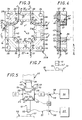
- the transmission member 10 which is intended to be interposed between a first member 11, said here for convenience, driving member, and a second member 12, said here for convenience, driven member , Figure 5, comprises a hollow housing 13, and a core 14 mounted floating in all directions in said housing 13, Figures 1 and 2, said core comprising at least two arms 16, which open one and the other at the outside of the housing 13, and to each of which a driving or driven member is liable to be subjected.
- the arms 16 form an angle between them.
- four arms 16 are provided, which are arranged generally in a cross, and which form two by two between them an angle of 90 °.
- each arm 16 forms for it a straight cross section 18, and this end cross section 18 of each arm 16 is quadrangular.
- This end cross section 18 is for example square.
- the arms 16 of the core 14 are all identical to each other, and, in particular, their end cross sections 18 have the same surface.
- these arms 16 are, at their roots, linked in pairs by cylindrical connecting surfaces 19 with a large radius of curvature.
- the core 14 is generally in the form of a simple solid plate, with parallel faces, from which the arms 16 which it comprises are cut in one piece.
- Such a core 14 can, for example, be made of metal, in particular aluminum, or ceramic.
- the housing 13 is externally in the form of a generally parallelepipedal block.
- a housing 20 Internally, it comprises, for the core 14, a housing 20, the configuration of which is a homothetic replica of that of the core 14, a clearance J being provided in all directions between said core 14 and said housing 20.
- the housing 20 opens on the outside, on four opposite faces two by two of the housing 13, by quadrangular openings 21 homothetic of the end cross sections 18 of the arms 16 of the core 14.
- This clearance J is, for example, less than 0.5 tenths of a mm and preferably less than 2 hundredths of a mm
- such a clearance existing on either side of the core 14, for both directions in any direction it is in total, in any direction, for the two directions combined in such a direction, less than 1 tenth of a mm, and preferably less than 4 hundredths of a mm.
- end cross sections 18 of the arms 16 of the core 14 are flush with the corresponding faces of the housing 13.
- the housing 13 comprises, for defining the housing 20 of the core 14, two flanges 22A, 22B suitably facing one another.
- these flanges 22A, 22B are identical to each other, and, facing one another along a flat median surface 23, they each participate for half, at mid-thickness, in the definition of the housing 20 of the core 14 .
- Each flange 22A, 22B therefore comprises a sole 24 on which protrude, in the corners, four lateral bosses 26.
- the housing 13 further comprises two covers 28A, 28B which are each respectively superposed on the flanges 22A, 22B.
- the flanges 22A, 22B and the covers 28A, 28B which all have the same quadrangular contour, are joined together by threaded tie rods 29, arranged in their angles, parallel to the corresponding edges of the block which they form.
- each of the walls of the housing 20 which are opposite the arms 16 of the core 14 comprises at least one recess, which, by a network of pipes internal to the housing 13, detailed below, is likely to be placed in communication with a source of pressurized lifting fluid.
- said part of the walls of the housing 20 thus comprising nozzles 37 extends from the outlets outside 21 of this housing 20.
- nozzles 37 affect both the sole 24 of the flanges 22A, 22B and the side blocks 26 thereof.
- they extend in two rows in depth, towards the center of the housing 20, and, for each row, they are established in regular steps.
- the pipes provided in the housing 13 for serving the nozzles 37 affecting the side blocks 26 of the flanges 22A, 22B have holes 39 established parallel to each other in these side blocks 26, perpendicular to the corresponding flange 24, said nozzles 37 emerging directly in said holes 39.
- These pipes further comprise grooves 40, which are formed on the surfaces of the flanges 22A, 22B opposite the housing 20, and into which the preceding holes 39 open on the one hand, and, on the other hand, directly, the nozzles 37 of the sole 24 of these flanges 22A, 22B : in practice, in the embodiment shown, two annular grooves 40 concentric are provided, and these communicate transversely with each other by a passage 38.
- the pipes provided for serving the nozzles 37 finally comprise a bore 41 provided in the cover 28A, in line with one of the grooves 40 in the underlying flange 22A.
- this bore 41 of the cover 28A can be connected to a source of pressurized lifting fluid.
- the housing 13 comprises, in the central zone of the housing 20 provided for this core 14, at least one discharge passage 42 suitable for placing said housing in communication with a discharge, for example the atmosphere.
- a single discharge passage 42 is provided on either side of the core 14, and it successively comprises a bore 43 formed in the center of each flange 22A, 22B and a bore 44 formed, in the alignment of the previous one, in the center of each cover 28A, 28B.
- the housing 13 thus formed can be made of metal, for example aluminum, or of synthetic material; its nozzles 37 may for example be cylindrical and have a diameter of the order of 1 mm, and preferably of the order of 0.8 mm.
- the lifting fluid used is injected in the gap between the core 14 and the housing 20 of the housing 13, by the multiplicity of nozzles 37 provided for this purpose in this housing near the outlets outside that these arms 16 of the core 14, and it escapes therefrom through the exhaust section resulting on the one hand from the clearance J existing around said arms 16, at the outlets 21 outside the housing 20, and on the other part of the evacuation passages 42.
- the injection pressure of the lifting fluid is chosen according to the number and the diameter of the nozzles 37, of the exhaust section offered to said fluid, as described above, of the power to be brought into play between the driving member and the driven member concerned, and the amplitude of the vibrations likely to be applied to the core 14 by this driving member.
- this injection pressure is chosen to be sufficient so that, in any event, the core 14 floats, in service, inside the housing 13, without any contact therewith.
- the core 14 is mechanically and electrically isolated from the housing 13 by the cushion of lifting fluid interposed at all points between it and this housing 13, this lifting fluid having been chosen to be elastically compressible so as not to not transmit vibrations and being by itself electrically insulating.
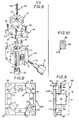
- the transmission member 10 can, for example, be fixed to the frame head 45 of any machining machine, and in particular of a machine for machining by electro-erosion or electro-chemistry, facing any support, work table 55 for example, suitable for holding, for example, the workpiece 57.
- the transmission member 10 For fixing the transmission member 10 according to the invention to the frame head 45, it is attached, for example by screws 46, on one of the faces of its housing 13 comprising at the outlet 21 of the housing 20, tapped holes 75 being provided for this purpose at the corners of this housing 13, an intermediate plate 49, and, the latter by screws 61 implemented by means of recesses 62 formed for this purpose on its underside in the form of embodiment shown in solid lines in Figure 6, is itself reported on an adapter or coupling device 47 suitable for allow connection to the fixing device 48 usually fitted to such a frame head 48.
- Two screws 61 may suffice.
- two screws 46 also may suffice for fixing the intermediate plate 49 to the housing 13; as shown, recesses 62 'can be provided at the upper part thereof for screws.
- the adapter or coupling device 47 may for example be of the type described in US Patent No. 3,271,848, such as those sold under the trade designation "IMEA t '.
- the electrode 12 to be used On the opposite face of the housing 13, it is then attached, at the end of the arm 16 corresponding to the core 14, on the transverse end surface 18 of such an arm 16, the electrode 12 to be used, which, in is a mixed electrode, only the end 50 of this electrode being made of graphite and constituting a machining tool, and said end 50 of this electrode 12 is, by a wire 51, connected to an electric generator 60 capable to charge her.
- the electrode 12 is attached to the core 14 by a threaded tie rod 65, which passes through the female part 63 of the coupling device 47 and the core 14, by means of a bore 66 thereof, for cooperation with a threaded bore 67 of said electrode 12, and which, by its head 68, bears on the opposite face of said core 14.
- the intermediate plate 49 In its central zone, the intermediate plate 49 has a recess 69, serving as a housing for the head 68 of the threaded tie rod 65, without contact with the latter.
- the intermediate plate 49 therefore makes it possible to prevent the vibrations do not propagate towards the coupling device 47.
- the electrode 12 can, for example, as shown in FIG. 6, project, on either side of its threaded bore 67, two pins 71 suitable for cooperating in engagement with complementary housings provided for this purpose on said core 14 (not visible in the figures).
- the vibration generator 11, or transducer is attached by any suitable means to the corresponding arm 16 of the core 14, on the transverse end surface 18 of this arm 16, and a wiring 53 connects it to a generator. impulses 54 appropriate.
- the vibration generator 11 which may for example be of the type sold by the company BRANSON, is attached to the core 14 by means of a threaded captive stud 72, which, on the one hand, cooperates with a threaded bore 73 of said core 14, and which, on the other hand, cooperates with a threaded bore, not visible in the figures, of said vibration generator 11.
- a second vibration generator 11 can, according to the invention, be attached to the arm 16 opposite the core 14, according to provisions similar to those described above.
- the adapter 47 can have any dimension, this dimension not necessarily having to be given to the half-wavelength of the vibrations used.
- the size of the transmission member 10 according to the invention can advantageously be reduced than if a vibration generator 11 was in line with the electrode 12, which facilitates implantation.
- a pressure detector 56 is preferably connected to one of the discharge passages 42 which the housing 13 includes, and, to this pressure detector 56, is controlled the driving member which constitutes the vibration generator 11, the pressure detector 56 controlling for example a switch 59 interposed on the wiring 53 controlling this vibration generator 11.
- a switch 58 also controlled by the pressure detector 56.
- the supply of the vibration generator 11, and possibly also that of the electrode 12, are systematically interrupted, in order to d 'prevent the core 14' from touching the casing 13.
- the pressure detector thus implemented can for example be a simple vacuum flap.
- the usual arrangements are also made so that the machining tool 50 and the workpiece 57 are immersed in an electrolyte.
- the machining tool 50 is carried by the electrode 12 and thus forms the driven member for the transmission member 10 according to the invention, while the member or part to be machined 57 was fixed on the work table 65 of the machine concerned or any other support integral with the frame thereof.
- machining tool 50 which, as before, can be connected by a wire 51 to the electric generator 60.
- the essential is, in the case of a machine for machining by electro-erosion or electro-chemistry, that the establishment of an electrical voltage between the machining tool 50 and the workpiece is ensured. to be machined 57.
- EDM machine As an EDM machine, it is pulsed; being an electro-chemical machining machine, it is pulsed or continuous.
- FIGS. 8 to 10 which relate in solid lines, by way of example, to the single flange 22B of the housing 13, it being understood that the flange 22A, shown diagrammatically in broken lines in FIG. 9, then jointly has an identical constitution, for each of the walls of the housing 20 provided for the core 14, the recess 77 necessary for blowing a lifting fluid extends over the entire width of such a wall.
- such a recess 77 extends, for each of said walls, from one of the bosses 26 framing the latter to the other, and, each of said bosses being affected by a similar recess 77, it belongs, like those here, an annular recess 78 continuously surrounding the arm 16 corresponding to the core 14, in the vicinity of the end of the latter.
- the pipes provided in the corresponding housing 13 for serving the recesses 78 thus formed in the housing 20 thereof comprise, from one recess 78 to another, at least one groove 80, which is formed on the surface of at least one of the flanges 22A, 22B facing said housing 20, and, in practice on the surface in question of each of these flanges 22A, 22B o
- This groove 80 affects each of the studs 26, extending, for example in a curve, as shown, from a recess 77 corresponding to another.
- the feed hole 41 is made in line with one of the recesses 77, and no cover 28A, 28B is necessary.
- the block forming the transmission member according to the invention advantageously has at least three orthogonal faces two by two capable of facilitating its implementation, namely a fixing face , for its adaptation to a machine frame, a power face, for setting up a driving member, and an outlet face, for setting up a driven member.
- one and / or the other of the covers that its housing optionally includes, or one and / or the other of the flanges thereof in the absence of such covers, may be replaced by an intermediate plate which, by a lateral drilling opening on its edge, allows, said drilling intersecting the transverse drilling normally provided for this purpose, a simultaneous supply of lifting fluid from two adjoining bootmakers.
- the core used comprises four arms.
- it may be greater than four, arms extending transversely on either side of a common sill, parallel to one another.
- this core has four cross arms, it is not necessary that from one branch of such a cross to the other said arms have the same length.
- the arms of the core could for example be tuned to the half-wavelength of the vibrations to be implemented, while, for the other branch of said cross, they could be tuned on a multiple of this half wavelength.
- the field of application of the invention is obviously not limited to that of machines for machining by ultrasound, electro-erosion or electro-chemistry, but extends more generally to that of any organ led to subject to vibrations on the part of a leading organ, or even to other actions on the part of such a leading organ, or to that of any driven member subjected to parasitic vibrations, said vibrations not having to be transmitted to the support frame, for example when the driven member is a tool for machining rotating parts.
Landscapes
- Engineering & Computer Science (AREA)
- Mechanical Engineering (AREA)
- Physics & Mathematics (AREA)
- Acoustics & Sound (AREA)
- Multimedia (AREA)
- Electrical Discharge Machining, Electrochemical Machining, And Combined Machining (AREA)
- Grinding And Polishing Of Tertiary Curved Surfaces And Surfaces With Complex Shapes (AREA)
- Apparatuses For Generation Of Mechanical Vibrations (AREA)
- Vibration Prevention Devices (AREA)
Applications Claiming Priority (2)
| Application Number | Priority Date | Filing Date | Title |
|---|---|---|---|
| FR8103511 | 1981-02-23 | ||
| FR8103511A FR2500336A1 (fr) | 1981-02-23 | 1981-02-23 | Organe de transmission a interposer entre un organe menant et un organe mene, en particulier outil vibrant |
Publications (2)
| Publication Number | Publication Date |
|---|---|
| EP0063501A1 true EP0063501A1 (de) | 1982-10-27 |
| EP0063501B1 EP0063501B1 (de) | 1984-07-04 |
Family
ID=9255508
Family Applications (1)
| Application Number | Title | Priority Date | Filing Date |
|---|---|---|---|
| EP82400260A Expired EP0063501B1 (de) | 1981-02-23 | 1982-02-15 | Schwingungsübertrager und Bearbeitungsmaschine mit solch einem Übertrager |
Country Status (6)
| Country | Link |
|---|---|
| US (1) | US4404449A (de) |
| EP (1) | EP0063501B1 (de) |
| JP (1) | JPS6051975B2 (de) |
| DE (1) | DE3260312D1 (de) |
| ES (1) | ES8306446A1 (de) |
| FR (1) | FR2500336A1 (de) |
Families Citing this family (4)
| Publication number | Priority date | Publication date | Assignee | Title |
|---|---|---|---|---|
| FR2526335A1 (fr) * | 1982-05-04 | 1983-11-10 | Legrand Sa | Organe de transmission a noyau flottant propre notamment a l'assistance ultrasonique d'un quelconque traitement, et application en particulier au compactage et au trefilage |
| US4670635A (en) * | 1984-08-10 | 1987-06-02 | Ex-Cell-O Corporation | Multi-electrode electrical discharge machining apparatus |
| DE3432942A1 (de) * | 1984-09-07 | 1986-03-20 | Manfred 7208 Spaichingen Sohmer | Haltevorrichtung fuer elektroden an funkenerosionsmaschinen |
| DE19653458A1 (de) * | 1996-12-20 | 1998-06-25 | Karlsruhe Forschzent | Verfahren zur Herstellung von Verformungsproben aus festen Einkristallen |
Citations (3)
| Publication number | Priority date | Publication date | Assignee | Title |
|---|---|---|---|---|
| US3390244A (en) * | 1965-07-06 | 1968-06-25 | Elox Inc | Machining apparatus of the electroerosive type |
| FR1599285A (de) * | 1967-12-25 | 1970-07-15 | ||
| BE820506A (fr) * | 1974-09-30 | 1975-01-16 | Generateur de vibrations. |
Family Cites Families (2)
| Publication number | Priority date | Publication date | Assignee | Title |
|---|---|---|---|---|
| US3072777A (en) * | 1960-03-25 | 1963-01-08 | Elox Corp Michigan | High frequency electrode vibration |
| US4336917A (en) * | 1979-10-11 | 1982-06-29 | Optimetrix Corporation | Shock and vibration isolation system |
-
1981
- 1981-02-23 FR FR8103511A patent/FR2500336A1/fr active Granted
-
1982
- 1982-02-15 EP EP82400260A patent/EP0063501B1/de not_active Expired
- 1982-02-15 DE DE8282400260T patent/DE3260312D1/de not_active Expired
- 1982-02-22 ES ES509809A patent/ES8306446A1/es not_active Expired
- 1982-02-23 JP JP57028021A patent/JPS6051975B2/ja not_active Expired
- 1982-03-19 US US06/350,238 patent/US4404449A/en not_active Expired - Fee Related
Patent Citations (3)
| Publication number | Priority date | Publication date | Assignee | Title |
|---|---|---|---|---|
| US3390244A (en) * | 1965-07-06 | 1968-06-25 | Elox Inc | Machining apparatus of the electroerosive type |
| FR1599285A (de) * | 1967-12-25 | 1970-07-15 | ||
| BE820506A (fr) * | 1974-09-30 | 1975-01-16 | Generateur de vibrations. |
Also Published As
| Publication number | Publication date |
|---|---|
| FR2500336A1 (fr) | 1982-08-27 |
| US4404449A (en) | 1983-09-13 |
| JPS57189729A (en) | 1982-11-22 |
| JPS6051975B2 (ja) | 1985-11-16 |
| FR2500336B1 (de) | 1984-04-06 |
| EP0063501B1 (de) | 1984-07-04 |
| ES509809A0 (es) | 1983-06-01 |
| ES8306446A1 (es) | 1983-06-01 |
| DE3260312D1 (en) | 1984-08-09 |
Similar Documents
| Publication | Publication Date | Title |
|---|---|---|
| EP0437839B1 (de) | Gehäuse für tauchfähige elektronische Schaltungen | |
| EP0462037B1 (de) | Elektroakustischer Unterwasserwandler | |
| FR2527118A1 (fr) | Machine a decouper par fil a decharges electriques | |
| CA1138024A (fr) | Generateur de gouttelettes d'encre pour imprimante a jet d'encre | |
| EP0063501B1 (de) | Schwingungsübertrager und Bearbeitungsmaschine mit solch einem Übertrager | |
| EP0308662B1 (de) | Zahnsteinentferner | |
| FR2541159A1 (fr) | Perfectionnements apportes aux outils de soudure par ultra-sons | |
| FR2695767A1 (fr) | Moteur piézo-électrique rotatif présentant une liaison stator-boîtier améliorée. | |
| EP0098756B1 (de) | Schwingungsübertragungsstück mit schwimmendem Kern | |
| FR2631457A1 (fr) | Recepteur de lasers tournants utilises pour le guidage d'engins, de travaux publics notamment | |
| FR2818180A1 (fr) | Dispositif de prehension destine a etre monte sur un bras de robot | |
| FR2577838A1 (fr) | Appareil de preparation et/ou de prereglage d'un outil pour machine d'usinage | |
| FR2647904A2 (fr) | Tete de controle par ultrasons | |
| FR2597826A1 (fr) | Flotteur modulaire et procede d'assemblage d'une pluralite de tels flotteurs pour constituer un engin flottant | |
| EP0449694B1 (de) | Elektrodenhaltervorrichtung zur elektroerosiven Bearbeitung | |
| FR2766053A1 (fr) | Fixation amelioree et rapide pour outils de travail d'une machine agricole | |
| EP0176452B1 (de) | Vorrichtung zum Tragen und zur verstellbaren Orientierung von verschiedenen Elementen bezüglich einer Referenzebene | |
| FR2688590A1 (fr) | Eprouvette de traction/compression triaxiale. | |
| EP1594647A1 (de) | Schneidplatte | |
| FR3134531A1 (fr) | Caisson d’aspiration apte à être désassemblé pour un préhenseur | |
| WO1994028853A1 (fr) | Appareil de massage et de nettoyage portatif a vibration ultrasonore | |
| EP0026688A1 (de) | Schwingungsvorrichtung mit piezoelektrischem Element für eine Flüssigkeitskanone, die für den Spritzkopf einer zerlegten Flüssigkeit bestimmt ist | |
| EP0987533B1 (de) | Verfahren zur Herstellung von Dehnungsaufnehmern | |
| FR2643771A1 (fr) | Capsule piezoelectrique a organes de maintien elastiques conducteurs | |
| FR2468431A1 (fr) | Appareil d'usinage electrique |
Legal Events
| Date | Code | Title | Description |
|---|---|---|---|
| PUAI | Public reference made under article 153(3) epc to a published international application that has entered the european phase |
Free format text: ORIGINAL CODE: 0009012 |
|
| AK | Designated contracting states |
Designated state(s): CH DE FR GB IT |
|
| 17P | Request for examination filed |
Effective date: 19821004 |
|
| ITF | It: translation for a ep patent filed | ||
| GRAA | (expected) grant |
Free format text: ORIGINAL CODE: 0009210 |
|
| AK | Designated contracting states |
Designated state(s): CH DE FR GB IT LI |
|
| REF | Corresponds to: |
Ref document number: 3260312 Country of ref document: DE Date of ref document: 19840809 |
|
| PLBE | No opposition filed within time limit |
Free format text: ORIGINAL CODE: 0009261 |
|
| STAA | Information on the status of an ep patent application or granted ep patent |
Free format text: STATUS: NO OPPOSITION FILED WITHIN TIME LIMIT |
|
| 26N | No opposition filed | ||
| PGFP | Annual fee paid to national office [announced via postgrant information from national office to epo] |
Ref country code: FR Payment date: 19920117 Year of fee payment: 11 |
|
| PGFP | Annual fee paid to national office [announced via postgrant information from national office to epo] |
Ref country code: GB Payment date: 19920207 Year of fee payment: 11 |
|
| PGFP | Annual fee paid to national office [announced via postgrant information from national office to epo] |
Ref country code: CH Payment date: 19920212 Year of fee payment: 11 |
|
| PGFP | Annual fee paid to national office [announced via postgrant information from national office to epo] |
Ref country code: DE Payment date: 19920221 Year of fee payment: 11 |
|
| ITTA | It: last paid annual fee | ||
| PG25 | Lapsed in a contracting state [announced via postgrant information from national office to epo] |
Ref country code: GB Effective date: 19930215 |
|
| PG25 | Lapsed in a contracting state [announced via postgrant information from national office to epo] |
Ref country code: LI Effective date: 19930228 Ref country code: CH Effective date: 19930228 |
|
| GBPC | Gb: european patent ceased through non-payment of renewal fee |
Effective date: 19930215 |
|
| PG25 | Lapsed in a contracting state [announced via postgrant information from national office to epo] |
Ref country code: FR Effective date: 19931029 |
|
| REG | Reference to a national code |
Ref country code: CH Ref legal event code: PL |
|
| PG25 | Lapsed in a contracting state [announced via postgrant information from national office to epo] |
Ref country code: DE Effective date: 19931103 |
|
| REG | Reference to a national code |
Ref country code: FR Ref legal event code: ST |