EP0063577B1 - Laser a recombinaison - Google Patents
Laser a recombinaison Download PDFInfo
- Publication number
- EP0063577B1 EP0063577B1 EP81902905A EP81902905A EP0063577B1 EP 0063577 B1 EP0063577 B1 EP 0063577B1 EP 81902905 A EP81902905 A EP 81902905A EP 81902905 A EP81902905 A EP 81902905A EP 0063577 B1 EP0063577 B1 EP 0063577B1
- Authority
- EP
- European Patent Office
- Prior art keywords
- laser
- recombination
- plasma
- excitation
- pin
- Prior art date
- Legal status (The legal status is an assumption and is not a legal conclusion. Google has not performed a legal analysis and makes no representation as to the accuracy of the status listed.)
- Expired
Links
- 238000005215 recombination Methods 0.000 title claims description 60
- 230000006798 recombination Effects 0.000 title claims description 57
- 230000005284 excitation Effects 0.000 claims description 27
- 239000000463 material Substances 0.000 claims description 26
- 150000002500 ions Chemical class 0.000 claims description 24
- 230000005855 radiation Effects 0.000 claims description 15
- 238000001816 cooling Methods 0.000 claims description 13
- 239000012212 insulator Substances 0.000 claims description 11
- 239000002245 particle Substances 0.000 claims description 8
- 239000002184 metal Substances 0.000 claims description 7
- 229910052751 metal Inorganic materials 0.000 claims description 7
- 230000009471 action Effects 0.000 claims description 6
- 239000007789 gas Substances 0.000 description 59
- 210000002381 plasma Anatomy 0.000 description 59
- 125000004429 atom Chemical group 0.000 description 21
- 239000000872 buffer Substances 0.000 description 19
- 230000007246 mechanism Effects 0.000 description 18
- 210000004027 cell Anatomy 0.000 description 17
- 241000894007 species Species 0.000 description 14
- 230000007704 transition Effects 0.000 description 14
- 230000005281 excited state Effects 0.000 description 12
- 230000007935 neutral effect Effects 0.000 description 11
- 238000009792 diffusion process Methods 0.000 description 8
- 238000000034 method Methods 0.000 description 6
- 230000000694 effects Effects 0.000 description 5
- 230000005283 ground state Effects 0.000 description 5
- 238000010438 heat treatment Methods 0.000 description 5
- 238000004519 manufacturing process Methods 0.000 description 5
- RYGMFSIKBFXOCR-UHFFFAOYSA-N Copper Chemical compound [Cu] RYGMFSIKBFXOCR-UHFFFAOYSA-N 0.000 description 4
- 239000010949 copper Substances 0.000 description 4
- 239000000203 mixture Substances 0.000 description 4
- 230000015572 biosynthetic process Effects 0.000 description 3
- 229910052802 copper Inorganic materials 0.000 description 3
- 239000003574 free electron Substances 0.000 description 3
- 230000033001 locomotion Effects 0.000 description 3
- 230000008569 process Effects 0.000 description 3
- OKTJSMMVPCPJKN-UHFFFAOYSA-N Carbon Chemical compound [C] OKTJSMMVPCPJKN-UHFFFAOYSA-N 0.000 description 2
- 239000003990 capacitor Substances 0.000 description 2
- 238000010586 diagram Methods 0.000 description 2
- 239000001307 helium Substances 0.000 description 2
- 229910052734 helium Inorganic materials 0.000 description 2
- SWQJXJOGLNCZEY-UHFFFAOYSA-N helium atom Chemical compound [He] SWQJXJOGLNCZEY-UHFFFAOYSA-N 0.000 description 2
- 230000003993 interaction Effects 0.000 description 2
- 230000009467 reduction Effects 0.000 description 2
- 230000035939 shock Effects 0.000 description 2
- 230000006641 stabilisation Effects 0.000 description 2
- 238000011105 stabilization Methods 0.000 description 2
- RZVAJINKPMORJF-UHFFFAOYSA-N Acetaminophen Chemical compound CC(=O)NC1=CC=C(O)C=C1 RZVAJINKPMORJF-UHFFFAOYSA-N 0.000 description 1
- 239000006173 Good's buffer Substances 0.000 description 1
- 238000010521 absorption reaction Methods 0.000 description 1
- 229910052799 carbon Inorganic materials 0.000 description 1
- 230000015556 catabolic process Effects 0.000 description 1
- 210000002421 cell wall Anatomy 0.000 description 1
- 239000000919 ceramic Substances 0.000 description 1
- 238000006243 chemical reaction Methods 0.000 description 1
- 230000008878 coupling Effects 0.000 description 1
- 238000010168 coupling process Methods 0.000 description 1
- 238000005859 coupling reaction Methods 0.000 description 1
- 230000006378 damage Effects 0.000 description 1
- 230000003111 delayed effect Effects 0.000 description 1
- 238000007599 discharging Methods 0.000 description 1
- 238000006073 displacement reaction Methods 0.000 description 1
- 238000010494 dissociation reaction Methods 0.000 description 1
- 230000005593 dissociations Effects 0.000 description 1
- 238000009826 distribution Methods 0.000 description 1
- 239000011888 foil Substances 0.000 description 1
- 239000011521 glass Substances 0.000 description 1
- PCHJSUWPFVWCPO-UHFFFAOYSA-N gold Chemical compound [Au] PCHJSUWPFVWCPO-UHFFFAOYSA-N 0.000 description 1
- 239000010931 gold Substances 0.000 description 1
- 229910052737 gold Inorganic materials 0.000 description 1
- 229910002804 graphite Inorganic materials 0.000 description 1
- 239000010439 graphite Substances 0.000 description 1
- CPBQJMYROZQQJC-UHFFFAOYSA-N helium neon Chemical compound [He].[Ne] CPBQJMYROZQQJC-UHFFFAOYSA-N 0.000 description 1
- 239000002784 hot electron Substances 0.000 description 1
- 239000001257 hydrogen Substances 0.000 description 1
- 229910052739 hydrogen Inorganic materials 0.000 description 1
- 125000004435 hydrogen atom Chemical class [H]* 0.000 description 1
- 238000005259 measurement Methods 0.000 description 1
- 229910052754 neon Inorganic materials 0.000 description 1
- 239000005297 pyrex Substances 0.000 description 1
- 239000004065 semiconductor Substances 0.000 description 1
- 238000004544 sputter deposition Methods 0.000 description 1
- 230000002123 temporal effect Effects 0.000 description 1
- 238000009834 vaporization Methods 0.000 description 1
- 230000008016 vaporization Effects 0.000 description 1
Images

Classifications
-
- H—ELECTRICITY
- H01—ELECTRIC ELEMENTS
- H01S—DEVICES USING THE PROCESS OF LIGHT AMPLIFICATION BY STIMULATED EMISSION OF RADIATION [LASER] TO AMPLIFY OR GENERATE LIGHT; DEVICES USING STIMULATED EMISSION OF ELECTROMAGNETIC RADIATION IN WAVE RANGES OTHER THAN OPTICAL
- H01S3/00—Lasers, i.e. devices using stimulated emission of electromagnetic radiation in the infrared, visible or ultraviolet wave range
- H01S3/14—Lasers, i.e. devices using stimulated emission of electromagnetic radiation in the infrared, visible or ultraviolet wave range characterised by the material used as the active medium
- H01S3/22—Gases
-
- H—ELECTRICITY
- H01—ELECTRIC ELEMENTS
- H01S—DEVICES USING THE PROCESS OF LIGHT AMPLIFICATION BY STIMULATED EMISSION OF RADIATION [LASER] TO AMPLIFY OR GENERATE LIGHT; DEVICES USING STIMULATED EMISSION OF ELECTROMAGNETIC RADIATION IN WAVE RANGES OTHER THAN OPTICAL
- H01S3/00—Lasers, i.e. devices using stimulated emission of electromagnetic radiation in the infrared, visible or ultraviolet wave range
- H01S3/09—Processes or apparatus for excitation, e.g. pumping
- H01S3/097—Processes or apparatus for excitation, e.g. pumping by gas discharge of a gas laser
- H01S3/09707—Processes or apparatus for excitation, e.g. pumping by gas discharge of a gas laser using an electron or ion beam
-
- H—ELECTRICITY
- H01—ELECTRIC ELEMENTS
- H01S—DEVICES USING THE PROCESS OF LIGHT AMPLIFICATION BY STIMULATED EMISSION OF RADIATION [LASER] TO AMPLIFY OR GENERATE LIGHT; DEVICES USING STIMULATED EMISSION OF ELECTROMAGNETIC RADIATION IN WAVE RANGES OTHER THAN OPTICAL
- H01S3/00—Lasers, i.e. devices using stimulated emission of electromagnetic radiation in the infrared, visible or ultraviolet wave range
- H01S3/09—Processes or apparatus for excitation, e.g. pumping
- H01S3/097—Processes or apparatus for excitation, e.g. pumping by gas discharge of a gas laser
- H01S3/0977—Processes or apparatus for excitation, e.g. pumping by gas discharge of a gas laser having auxiliary ionisation means
- H01S3/09775—Processes or apparatus for excitation, e.g. pumping by gas discharge of a gas laser having auxiliary ionisation means by ionising radiation
Definitions
- the present invention pertains to the field of recombination lasers.
- a recombination laser which has the features set out in the preamble of claim 1 is known from Applied Physics Letters, Vol. 36, No. 8, April 1980, pages 615-617.
- the He-Neon laser at 632 nm is perhaps the most well-known example of a neutral atomic species laser, but its efficiency is less than 0.1 percent.
- Commercially available Helium-Neon lasers typically require 10 W or more of electrical power to provide 1 or 2 mW of laser power at 632 nm.
- the copper laser probably the only neutral atomic laser with an efficiency above 1 percent, having yielded efficiencies as high as 2 percent, has problems in achieving long life at such efficiencies due to the difficulty involved in generating the required densities of copper vapor.
- the short pulse length and high gain further restrict the use of the copper laser.
- An efficient recombination laser as claimed in claim 1 comprises at least one laser cavity, a gaseous laser material disposed in the cavity, and excitation and confinement means for providing at least one plasma discharge in said laser material, which plasma discharge is initially confined to a cylindrical region along the axis of the laser cavity.
- the plasma in the gaseous laser material then expands outward radially from the cylindrical region at the axis of the cavity into a second region of annular form and cools by interacting with the adjacent unexcited gas.
- the maximum laser gain is provided in said annular second region, which annular region is adjacent to and surrounds the initial discharge cylindrical region.
- the means for providing the plasma discharge comprises two pin-type electrodes which extend into the laser cavity along the cavity axis.
- the density of the gaseous laser material is kept low enough to minimize radiation trapping and a buffer gas is added to the cavity to provide gas pressure sufficient to confine the discharge to a small central region along the cavity axis and sufficient to reduce the plasma electron temperature for optimal laser gain.
- the buffer gas also allows expansion and cooling of the plasma to occur without having interactions between the laser material and the cavity wall destroy excited states.
- Helium is a good buffer gas because its high ionization potential causes most of the plasma excitation to occur in the gaseous laser material and because its low mass provides rapid cooling of the electrons in the plasma.
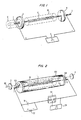
- Fig. 1 shows elements of an embodiment of a plasma-recombination laser fabricated according to the present invention.
- Electrodes 1 and 2 which extend into a long, large diameter cylindrical laser cavity through the axes of mirrors 3 and 4, are pin-type electrodes.
- a pulsed electrical discharge between electrodes 1 and 2 is initiated by applying a high-voltage, high-current pulse from power supply means 5 between the two pin-type electrodes 1 and 2.
- This produces a plasma in a gaseous material disposed between the electrodes, which plasma is confined during the current pulse, by means hereinafter described, to a cylindrical region 11 of the order of 1 cm in diameter or less along the axis of the laser cavity.
- the plasma then expands outward in a radial direction.
- a buffer gas may be added to the laser cavity.
- the buffer gas is added at a high enough gas pressure to confine the plasma discharge region to a small central region along the laser cavity axis.
- the buffer gas also reduces the plasma electron temperature by collisional de-excitation to provide optimal laser gain.
- the buffer gas also allows expansion and cooling of the plasma to occur without having interactions between the laser material and the cavity wall destroy excited states.
- the buffer gas chosen should have a higher ionization potential than the gaseous laser material in order to minimize energy loss due to ionization of the buffer gas by the electrical discharge.
- the buffer gas has a higher ionization potential than the gaseous laser material, the energy loss to the buffer gas is partially offset by the physical mechanisms of charge transfer and Penning ionization, which mechanisms provide for transfer of buffer gas excitation energy back to the gaseous laser material.
- Helium is a good choice for a buffer gas because it has such a high ionization potential that most of the excitation occurs in the gaseous laser material and because its low mass provides a rapid cooling of the plasma electrons due to collisional de-excitation.
- Fig. 2 shows an embodiment of the present invention which utilizes a 5.08 cm (2 inch) diameter by 15.24 cm (6 inch) long cylindrical Pyrex gas cell 150.
- the cell was fitted with two copper wire electrodes 1 and 2 whose ends were separated by 6-8 cm.
- the initial plasma 11 was created in a 1000:1 mixture of He:Xe at various pressures by discharging 0.01 pF capacitor 51, initially charged to 18 kv by DC supply 52, by means of 3-electrode spark gap 53 and trigger pulse input means 54. This produced a visible plasma 11 having approximately a 1 cm diameter.
- the ends of gas cell 150 were fitted with KCL Brewster's angle windows 155 and 156.
- the recombination laser resonator cavity was formed by two 6 meter radius of curvature, gold coated concave mirrors 3 and 4.
- Mirror 3 had a 1 mm diameter central coupling hole (not shown) for the 2.026 pm laser beam 60.
- the distance between the axis of this laser resonator and the axis of the cylindrical gas cell was continuously adjustable from 0 (on axis) to ⁇ 2.5 cm.
- the optimum gas mixture was a 1000:1 mixture of He:Xe where Xe was the active species and He acted as a buffer.
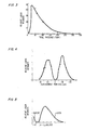
- Fig. 4 shows a plot of the relative laser intensity on the 2.026 um line in a 1000:1 mixture of He:Xe at 40 Torr total pressure as a function of distance from the axis of the gas cell.
- the region of gain clearly occurs in annular region 10 beyond initial plasma 11.
- FIG. 5 A trace of an oscilloscope photograph of the temporal behavior of this device operating at a total pressure of 20 Torr is shown in Fig. 5.
- the start of the laser pulse is seen to be delayed approximately 2 psec from the termination of the current pulse. This delay is a characteristic feature of recombination lasers.
- Several emission lines were observed in laser action. The strongest was the 2.026 ⁇ m 5d[3/2]°-6p[3/2] transition in Xe. The maximum observed small-signal gain on this transition was greater than 10 percent/cm.
- the highest output power from this device was about 300 Watts peak.
- the maximum possible input energy is the 1.62 J of energy stored in the 0.01 pF capacitor charged to 18 kV. Consequently, the overall efficiency of this device was at least 0.1 percent and probably a good deal higher, since power was extracted from only a small fraction of the active volume and no account has been taken of the energy dissipated in the spark gap.
- a shock wave travels away from initial plasma region 11 in the buffer gas at a velocity of about 5x10 5 cm/sec.
- the cell In order that the shock wave reflected from the gas cell walls not disturb the homogeneity of gain region 10 during the time of peak gain (see Fig. 5), i.e., 6 psec from the end of the current pulse, the cell must be at least 2.0 cm in radius.
- Fig. 4 shows that the laser gain extends out to approximately 25 mm from the axis of the cell. Consequently, the minimum gas cell diameter for an efficient laser is about 5 cm.
- the maximum gas .cell diameter can be as large as desired. If a number (N) of cylindrically-shaped initial plasmas are arranged in parallel in the same gas cell, the cross sectional area of the gas cell would necessarily be N times the area of a single plasma.
- the limits on the length, here taken as the spacing between electrodes, of an efficient annular recombination laser are also quite wide.
- the minimum length is-set by the small signal gain of the laser transition. The highest reported, to date, is 55 percent/cm in Xe at 2.026 ⁇ m. To overcome unavoidable losses in the windows and mirrors of say 0.2 percent, the minimum length for such a laser is about 1 mm.
- the maximum length for the laser is set by the practical difficulty of maintaining the straightness of the initial cylindrically-shaped plasma and several techniques are disclosed hereinafter to achieve said straightness.
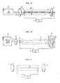
- Fig. 6 shows basic elements of a further embodiment of the present invention.
- Insulator rod 25 is supported between pin-type electrodes 1 and 2.
- Pin-type electrodes are inserted into the cavity formed by mirrors 3 and 4.
- a coronal discharge along the surface of insulator rod 25 is formed.
- the coronal discharge tends to preionize the laser material in the cylindrical region 26 near the insulator rod 25 and stabilize the discharge, causing it to occupy a small cylindrical region near insulator rod 25.
- the plasma formed in region 26 expands into annular gain region 27 where laser action is produced as described hereinabove.
- stabilization of the discharge we mean the production of a discharge which is uniformly distributed in space.
- the insulator may be fabricated from glass, ceramic or some semiconductor material such as carbon or graphite.
- insulator rod 25 may be illuminated with UV light to produce photoemission of electrons. These photo-produced electrons preionize a defined gas volume and provide, thereby, a stabilization of the discharge produced by the high-voltage, high-current pulse impressed across pin-type electrodes 1 and 2.
- the means for providing the UV light are well known to those skilled in the art.
- Fig. 7 shows basic elements of a further embodiment of the present invention.
- Rod 30 is made up of a series of metal segments 1, 32, 34 and 2 and insulating rod segments 31, 33 and 35.
- a high-voltage, high-current pulse produced by means 5 is applied to electrodes 1 and 2, stabilized cylindrical plasma regions 41, 42 and 43 are produced.
- Metal segments 32 and 34 "short circuit" the discharge in the various positions adjacent thereto along the rod so that the plasmas are confined to the aforesaid regions adjacent the insulator rods.
- Use of such a segmented plasma excitation is known to result in an increase in the cooling rate, an increase in the plasma recombination rate and, hence, in higher laser gain and output
- Fig. 8 shows basic elements of a further embodiment of the present invention.
- Gas filled flash lamp 52 is disposed between pin-type electrodes 1 and 2.
- UV light is provided.
- This UV light ionizes a small gas volume 53 near the lamp.
- This preionized region 53 near flash lamp 52 tends to stabilize the plasma formation near or on the outer surface of the lamp.
- the gas volume surrounding flash lamp 52 may be seeded in accordance with known techniques with a material that is easily photoionized with UV and that has no absorption at the desired recombination laser wavelength.
- Fig. 9 shows basic elements of a further embodiment of the present invention.
- Beam 100 output from UV laser source 63, passes through mirror 130 and UV transmitting window 62 in electrode 61 to impinge upon the gaseous laser material in region 65.
- the UV radiation preionizes the cylindrical gas volume on the axis of the gas cell.
- a high-voltage, high-current pulse produced by means 5 is applied to metal ring electrode 61 and metal pin-type electrode 64, a stabilized plasma is produced in cylindrical region 67.
- the further operation of this embodiment is as has been described hereinabove.
- Fig. 10 shows basic elements of another embodiment of the present invention.
- Beam of particles 110 e.g., electrons, output from particle source 75, passes through mirror 131 and metal foil electrode 70 to impinge upon Faraday cup electrode 76.
- Faraday cup 76 includes a mirror 132, which mirror forms a resonant laser cavity with mirror 131.
- Mirror 132 may be, e.g., a metallic mirror.
- the particle beam produces a plasma on the axis of the gas cell in region 71.
- a high-voltage, high-current pulse produced by means 5 is applied to metal electrode 70 and Faraday cup electrode 76, a stabilized plasma is produced in region 71.
- the further operation of this embodiment is as has been described hereinabove.
- Fig. 11 shows basic elements of a further embodiment of the present invention.
- Thin wire 81 is located on the axis of the gas cell. Enough current is caused to flow through the wire from means 5 so that it will explosively vaporize. This operates both to stabilize the discharge to a thin cylindrical region and to provide the active element.
- the initial dimensions of wire are selected to result in the optimum concentration of active element after vaporization.
- the embodiments described hereinabove may be utilized in a parallel operation.
- a number of pairs of pin-type electrodes could be placed in a gas cell and pulsed simultaneously to provide a larger active volume.
- the laser can be used to produce lasing in ionic species, the exposition is focused primarily on the neutral atom laser for the sake of clarity.
- An ideal plasma-recombination laser operates in the following manner: The atoms of some element E are excited, e.g. by an electrical current pulse within a gaseous medium, and some fraction are ionized into state E (z+1)+ , as shown in Fig. 12, where Z could be any charge state of element E. Under suitable conditions the resulting plasma of electrons and ions of element E expands and the density is reduced. The expanding hot electrons interact with a surrounding cool gas and are cooled, thereby causing the electron-ion recombination rate to increase rapidly.
- the electrons and ions recombine and the captured electrons move downward in energy, via collisions with the free electron continuum, through the highly excited states of E Z+ until a significant gap in the energy levels of that charge state of E is reached.
- the collisional decay rate across the gap is reduced and produces a bottleneck, which bottleneck causes the population density to build up in levels immediately above the gap. A population inversion will then develop with respect to one or more lower levels and laser action can be achieved across the gap if a high decay rate for the lower laser level is present.
- Type I or Type II decay schemes are possible depending upon the choice of atomic species, the charge state of that species and the exact plasma conditions. In either scheme a minimum number of atoms having electrons in the lower laser level is desirable.
- the stage of ionization i.e. the value of Z in E Z+
- Z is an important parameter in designing a recombination laser.
- For the lower ionization stages (Z 1, 2, 3) this requires an initial plasma density in the range of 10 15 ⁇ 10 16 cm- 3 as shown in Fig. 12.
- the specific initial charge state (Z+1) is determined by the electron temperature during the formation of the plasma.
- the optimum plasma conditions for producing a population inversion have been found to lie at a somewhat lower plasma density, 10 14 cm- 3 or slightly lower. This lower density is needed to minimize the unwanted collisional depopulation of the upper-laser-level.
- the efficiency of a recombination laser is determined by the product of three efficiency factors: the efficiency of ion production, the efficiency of recombination of ions into the upper laser level, and the quantum efficiency of the laser, i.e., the laser transition energy divided by the ionization'energy. For the moment let us assume that the lower laser level is rapidly depleted.
- the principal energy losses during ion production are due to a) direct excitation of levels in the atom which lie below the upper laser level, b) excitation of electrons into unwanted excited states of the ion, c) radiation losses by free-free transitions in the electron continuum, brehmstrahlung, and by free-bound transitions, radiative recombination, and d) thermal heating of the atoms and the ions.
- Loss (a) the loss due to direct excitation of lower levels is not a large loss if the electron density develops at a rapid rate since multi-step ionization can occur if the ionization rate from the lower excited levels exceeds their radiative decay rate.
- the electron density at which the multi-step ionization occurs is in the range of 10 15 to -10 16 cm- 3 . If the ground state atomic density is higher than 10 14 cm- 3 then radiative trapping will reduce the radiative decay rate and thereby reduce the required electron density for multi-step ionization.
- the electron density at which multi-step ionization dominates over untrapped radiative decay is in the range of 10 13 to 10 14 cm- 3 .
- Loss (c) radiation losses in the form of free-free and free-bound transitions can become so large when the electron density becomes too high that atoms will be cycled through the excitation mechanism several times during an excitation electrical pulse. A description of these losses is given in an article entitled "A Calculation of the Instantaneous Population Densities of the Excited Levels of Hydrogen-like Ions in a Plasma", Proceedings Phys. Soc., Vol. 82, 1963, pp. 641-654, by R. W. P. McWhirter and A. G. Hearn. Their calculations indicate that an upper limit for the electron density of 10 16 cm- 3 would be required to minimize these losses for excitation pulses of 1 ps or less duration.
- the diffusion decay rate for a tube in which the length is much greater than the bore radius r is given by: where D a is the ambipolar diffusion coefficient, typically 800 cm 2 Torr sec -1 , and p is the gas pressure in Torr. For a 3 mm bore radius r and a pressure of 1 Torr, the diffusion decay rate is approximately 5x10 4 sec -1 . As is evident from EQ. 2, this diffusion decay loss rate can be minimized by increasing gas pressure and increasing bore size.
- the second ion decay mechanism involves the rate, R m , or the conversion of E + ions to ions. While this mechanism is not well known for most ions, it is probably not significant as long as the density of the lasing species is kept below ⁇ 10 16 cm- 3 . Even if the mechanism were significant, it would not necessarily produce a loss in efficiency in an atomic recombination laser since it is quite possible that dissociation of will occur into an atomic state at or above the upper laser level. We therefore assume that this mechanism has a negligible effect on reducing the efficiency of the laser.
- the radiative recombination rate, R r can be approximated by the following expression for recombination from single ions to neutral atoms: where n e is the electron density in cm- 3 and T e is the electron temperature in eV.
- This mechanism involves the binding of an electron to an ion in a specific state of the neutral atom, either an excited state or the ground state, with the simultaneous emission of a photon.
- the photon has an energy equal to the difference between the free-electron energy and the bound state energy.
- This mechanism leads to an inefficiency in the recombination laser excitation because those atoms that recombine to bound levels lying below the upper laser level bypass the upper laser level during their subsequent decay.
- atoms in excited states lying above the upper laser level also bypass that level by radiative decay.
- the collisional recombination rate, R c is approximated by: R c is much more sensitive to both n e and T e than is R r .
- the collisional recombination mechanism is the most effective one in providing an efficient recombination laser since every electron that recombines with E + through this mechanism is moved downward in energy by collisions with free-electrons having density n e and temperature T e .
- the highest rate of downward movement is to energetically adjacent levels, i.e., the population moves downward in energy in small steps. Thus, every electron that recombines by this mechanism is moved downward to the upper laser level.
- the recombination efficiency factor could approach 100 percent, where R c is greater than R d , R m , and R r , if an atomic species having an appropriate level scheme is available when a large inversion occurs during the collisional recombination mechanism in order to allow all of the energy to be extracted from the upper laser level, by stimulated emission.
- n e and T e at which R c equals R r is obtained from EQS. 3 and 4 and is given by Fig. 14 shows a graph of this equation.
- the region above and to the left of line 100 where R c dominates over R r is the region which denotes the necessary condition for an efficient recombination laser.
- T e 2 eV
- its initial location on Fig. 14 would be at Position 1.
- Such a set of initial conditions is not unreasonable for a predominantly single ionized plasma with a high percentage of ionization.
- the decay of the lower laser level is determined by n e and T e .
- the depletion of the lower laser level is automatically provided for when an atomic system is chosen which has a suitable group of levels, of which the lower laser level is a high lying level.
- the electron density should be kept low enough to minimize electron collisional de-excitation across the gap, which de-excitation would result in a radiationless depletion of the upper laser level.
- a buffer gas would reduce T e , reduce the diffusion loss rate to the walls, and at the same time provide a background gas into which the plasma could expand and cool in order to optimize the cooling trajectory.
- Adding a buffer gas does introduce the possibility of excitation and ionization energy being lost to the buffer gas species.
- a high ionization potential gas such as He
- most of the ionization energy would go to the lower ionization potential laser species and any ionization energy taken by the He would most likely be transferred back to the laser species via charge transfer or Penning ionization.
- the low mass of the He atoms would provide an ideal rapid cooling mechanism for the electrons as the plasma expands into the cool surrounding gas. Implicit in these requirements is the fact that the plasma would have to be produced in only a small fraction of the available volume such that it can subsequently expand into the larger volume and cool.
- a pressure in the range of 10- 3 to 10 -1 Torr for the laser species This is based upon the requirement of maximum ion density which prevents radiative trapping from restricting decay of lower laser levels.
- T e in the range of 1 to 10 eV.
- the lower bound of 1 eV is needed so that electron-ion recombination is inhibited until the plasma expands sufficiently to where n e has the value specified hereinabove and shown in Fig. 12.
- the upper bound of 10 eV is used to keep down the rate of double ionization of the laser species, which double ionization will lower the laser efficiency.
Landscapes
- Physics & Mathematics (AREA)
- Electromagnetism (AREA)
- Engineering & Computer Science (AREA)
- Plasma & Fusion (AREA)
- Optics & Photonics (AREA)
- Health & Medical Sciences (AREA)
- Toxicology (AREA)
- Lasers (AREA)
Claims (9)
Applications Claiming Priority (2)
| Application Number | Priority Date | Filing Date | Title |
|---|---|---|---|
| US06/202,069 US4369514A (en) | 1980-10-30 | 1980-10-30 | Recombination laser |
| US202069 | 1988-06-03 |
Publications (3)
| Publication Number | Publication Date |
|---|---|
| EP0063577A1 EP0063577A1 (fr) | 1982-11-03 |
| EP0063577A4 EP0063577A4 (fr) | 1985-07-01 |
| EP0063577B1 true EP0063577B1 (fr) | 1987-10-14 |
Family
ID=22748386
Family Applications (1)
| Application Number | Title | Priority Date | Filing Date |
|---|---|---|---|
| EP81902905A Expired EP0063577B1 (fr) | 1980-10-30 | 1981-10-13 | Laser a recombinaison |
Country Status (8)
| Country | Link |
|---|---|
| US (1) | US4369514A (fr) |
| EP (1) | EP0063577B1 (fr) |
| JP (2) | JPS57501655A (fr) |
| CA (1) | CA1158756A (fr) |
| DE (1) | DE3176489D1 (fr) |
| GB (1) | GB2088121B (fr) |
| IL (1) | IL64131A (fr) |
| WO (1) | WO1982001622A1 (fr) |
Families Citing this family (13)
| Publication number | Priority date | Publication date | Assignee | Title |
|---|---|---|---|---|
| US4450568A (en) * | 1981-11-13 | 1984-05-22 | Maxwell Laboratories, Inc. | Pumping a photolytic laser utilizing a plasma pinch |
| US4498182A (en) * | 1982-06-18 | 1985-02-05 | At&T Bell Laboratories | Continuous wave sper laser |
| USH66H (en) | 1983-12-21 | 1986-05-06 | At&T Bell Laboratories | Pulsed plasma generation of extreme ultraviolet radiation |
| SU1674299A1 (ru) * | 1987-01-28 | 1991-08-30 | Научно-исследовательский центр по технологическим лазерам АН СССР | Лазер на 3Р - 3 S-переходах неона |
| US4889605A (en) * | 1987-12-07 | 1989-12-26 | The Regents Of The University Of California | Plasma pinch system |
| US4994715A (en) * | 1987-12-07 | 1991-02-19 | The Regents Of The University Of California | Plasma pinch system and method of using same |
| US5048163A (en) * | 1987-12-07 | 1991-09-17 | Asmus John F | System for processing semiconductor materials |
| ATE127651T1 (de) * | 1989-05-04 | 1995-09-15 | Univ California | Vorrichtung und verfahren zur behandlung von materialien. |
| DE4002048C2 (de) * | 1990-01-24 | 1993-11-18 | Deutsche Forsch Luft Raumfahrt | Rekombinationslaser |
| JPH0732073B2 (ja) * | 1991-07-19 | 1995-04-10 | 工業技術院長 | 極短波長レーザ用プラズマ発生装置 |
| US6621848B1 (en) | 2000-04-25 | 2003-09-16 | The Boeing Company | SECOIL reprocessing system |
| US6804327B2 (en) * | 2001-04-03 | 2004-10-12 | Lambda Physik Ag | Method and apparatus for generating high output power gas discharge based source of extreme ultraviolet radiation and/or soft x-rays |
| US9723703B2 (en) * | 2014-04-01 | 2017-08-01 | Kla-Tencor Corporation | System and method for transverse pumping of laser-sustained plasma |
Family Cites Families (13)
| Publication number | Priority date | Publication date | Assignee | Title |
|---|---|---|---|---|
| US3164782A (en) * | 1963-01-31 | 1965-01-05 | Jr Fred D Ordway | Gas-filled envelope for solid laser tube having internal electrodes |
| US3548335A (en) * | 1968-08-08 | 1970-12-15 | Us Army | Brush cathode discharge maser |
| US3757248A (en) * | 1972-07-31 | 1973-09-04 | Massachusetts Inst Technology | Pulsed gas laser |
| JPS5652471B2 (fr) * | 1972-12-05 | 1981-12-12 | ||
| US3916338A (en) * | 1972-11-07 | 1975-10-28 | Us Energy | Metal atom oxidation laser |
| US3864643A (en) * | 1973-11-23 | 1975-02-04 | Us Navy | Traveling wave vacuum spark and a travelling wave flashlamp |
| US3891941A (en) * | 1974-01-25 | 1975-06-24 | Us Army | Imploding cylinder metal vapor laser |
| US4135167A (en) * | 1975-05-30 | 1979-01-16 | Compagnie Generale D'electricite S.A. | Laser having a brief discharge between two elongated electrodes |
| ZA753563B (en) * | 1975-06-03 | 1977-01-26 | South African Inventions | A laser and its method of operation |
| DE2627611A1 (de) * | 1976-06-19 | 1977-12-22 | Licentia Gmbh | Co- oder co tief 2 -laser mit stiftanode |
| JPS53136995A (en) * | 1977-05-06 | 1978-11-29 | Hitachi Ltd | Discharge device |
| US4211983A (en) * | 1978-05-01 | 1980-07-08 | Avco Everett Research Laboratory, Inc. | High energy electron beam driven laser |
| US4228408A (en) * | 1978-10-23 | 1980-10-14 | The United States Of America As Represented By The Secretary Of The Navy | Pulsed cyclic laser based on dissociative excitation |
-
1980
- 1980-10-30 US US06/202,069 patent/US4369514A/en not_active Expired - Lifetime
-
1981
- 1981-10-13 DE DE8181902905T patent/DE3176489D1/de not_active Expired
- 1981-10-13 EP EP81902905A patent/EP0063577B1/fr not_active Expired
- 1981-10-13 WO PCT/US1981/001372 patent/WO1982001622A1/fr not_active Ceased
- 1981-10-13 JP JP56503422A patent/JPS57501655A/ja active Pending
- 1981-10-19 CA CA000388218A patent/CA1158756A/fr not_active Expired
- 1981-10-23 GB GB8132030A patent/GB2088121B/en not_active Expired
- 1981-10-27 IL IL64131A patent/IL64131A/xx unknown
-
1992
- 1992-08-10 JP JP1992056049U patent/JPH08772Y2/ja not_active Expired - Lifetime
Non-Patent Citations (1)
| Title |
|---|
| " LASER GAIN AROUND 18.2 nm PRODUCED IN CARBON PLASMA AT HULL UNIVERSITY"; LASER FOCUS; AUGUST 1980; pp. 24, 26 and 28 * |
Also Published As
| Publication number | Publication date |
|---|---|
| EP0063577A4 (fr) | 1985-07-01 |
| CA1158756A (fr) | 1983-12-13 |
| JPH0631160U (ja) | 1994-04-22 |
| JPS57501655A (fr) | 1982-09-09 |
| JPH08772Y2 (ja) | 1996-01-10 |
| DE3176489D1 (en) | 1987-11-19 |
| GB2088121A (en) | 1982-06-03 |
| IL64131A (en) | 1984-08-31 |
| EP0063577A1 (fr) | 1982-11-03 |
| WO1982001622A1 (fr) | 1982-05-13 |
| GB2088121B (en) | 1984-05-02 |
| US4369514A (en) | 1983-01-18 |
| IL64131A0 (en) | 1982-01-31 |
Similar Documents
| Publication | Publication Date | Title |
|---|---|---|
| Wood | High-pressure pulsed molecular lasers | |
| US4937832A (en) | Methods and apparatus for producing soft x-ray laser in a capillary discharge plasma | |
| EP0063577B1 (fr) | Laser a recombinaison | |
| US3886479A (en) | Electrode systems for gas discharge devices particularly gas lasers | |
| Silfvast et al. | Simple metal‐vapor recombination lasers using segmented plasma excitation | |
| Isaev et al. | Characteristics of pulsed discharges in copper bromide and copper HyBrID lasers | |
| US5467362A (en) | Pulsed gas discharge Xray laser | |
| US4381564A (en) | Waveguide laser having a capacitively coupled discharge | |
| US3891941A (en) | Imploding cylinder metal vapor laser | |
| Andreev et al. | Plasma-sheet CO2 laser | |
| US4441189A (en) | Foil electrode SPER light source | |
| US6167065A (en) | Compact discharge pumped soft x-ray laser | |
| US3531734A (en) | Ion laser having metal cylinders to confine the discharge | |
| US4680770A (en) | Dual beam gas ion laser | |
| Borisov et al. | Investigation of the characteristics of photoionization excimer lasers | |
| EP0103079B1 (fr) | Laser à recombinaison émettant une onde continue | |
| US4360924A (en) | Laser bottlenecking technique | |
| Long Jr et al. | Electric discharge pumping of excimer lasers | |
| Silvfast et al. | New laser systems | |
| Qi et al. | Observed enhanced fluorescence at 2177, 2163, 1923, and 1620 Å in C iii by photoexcitation with Mn vi line radiation at 310 Å | |
| Oraevskiĭ et al. | Z-pinch as the active medium of lasers for the far ultraviolet spectral region | |
| Witteman | Excimer Lasers: F2, N2 and H2 Lasers | |
| Burlamacchi | Excimer lasers: practical excimer laser sources | |
| Svelto | Types of lasers | |
| Schaefer et al. | Projects 8 and 9" Optically Controlled Discharges and Openinq Switches (C. Harjes, G. Hutchinson, L. Thurmond, R. Cooper, K. Schoenbach |
Legal Events
| Date | Code | Title | Description |
|---|---|---|---|
| PUAI | Public reference made under article 153(3) epc to a published international application that has entered the european phase |
Free format text: ORIGINAL CODE: 0009012 |
|
| AK | Designated contracting states |
Designated state(s): CH DE FR LI NL |
|
| 17P | Request for examination filed |
Effective date: 19821007 |
|
| 17Q | First examination report despatched |
Effective date: 19860513 |
|
| GRAA | (expected) grant |
Free format text: ORIGINAL CODE: 0009210 |
|
| AK | Designated contracting states |
Kind code of ref document: B1 Designated state(s): CH DE FR LI NL |
|
| REF | Corresponds to: |
Ref document number: 3176489 Country of ref document: DE Date of ref document: 19871119 |
|
| ET | Fr: translation filed | ||
| NLR4 | Nl: receipt of corrected translation in the netherlands language at the initiative of the proprietor of the patent | ||
| PLBE | No opposition filed within time limit |
Free format text: ORIGINAL CODE: 0009261 |
|
| STAA | Information on the status of an ep patent application or granted ep patent |
Free format text: STATUS: NO OPPOSITION FILED WITHIN TIME LIMIT |
|
| 26N | No opposition filed | ||
| PGFP | Annual fee paid to national office [announced via postgrant information from national office to epo] |
Ref country code: FR Payment date: 20000918 Year of fee payment: 20 |
|
| PGFP | Annual fee paid to national office [announced via postgrant information from national office to epo] |
Ref country code: NL Payment date: 20000925 Year of fee payment: 20 Ref country code: CH Payment date: 20000925 Year of fee payment: 20 |
|
| PGFP | Annual fee paid to national office [announced via postgrant information from national office to epo] |
Ref country code: DE Payment date: 20001229 Year of fee payment: 20 |
|
| PG25 | Lapsed in a contracting state [announced via postgrant information from national office to epo] |
Ref country code: LI Free format text: LAPSE BECAUSE OF EXPIRATION OF PROTECTION Effective date: 20011012 Ref country code: CH Free format text: LAPSE BECAUSE OF EXPIRATION OF PROTECTION Effective date: 20011012 |
|
| PG25 | Lapsed in a contracting state [announced via postgrant information from national office to epo] |
Ref country code: NL Free format text: LAPSE BECAUSE OF EXPIRATION OF PROTECTION Effective date: 20011013 |
|
| REG | Reference to a national code |
Ref country code: CH Ref legal event code: PL |
|
| NLV7 | Nl: ceased due to reaching the maximum lifetime of a patent |
Effective date: 20011013 |