EP0063597B1 - Ofen zum verbrennen von in fässern gespeicherten chemischen abfällen - Google Patents
Ofen zum verbrennen von in fässern gespeicherten chemischen abfällen Download PDFInfo
- Publication number
- EP0063597B1 EP0063597B1 EP81903139A EP81903139A EP0063597B1 EP 0063597 B1 EP0063597 B1 EP 0063597B1 EP 81903139 A EP81903139 A EP 81903139A EP 81903139 A EP81903139 A EP 81903139A EP 0063597 B1 EP0063597 B1 EP 0063597B1
- Authority
- EP
- European Patent Office
- Prior art keywords
- barrel
- holder
- combustion chamber
- burner
- incinerator
- Prior art date
- Legal status (The legal status is an assumption and is not a legal conclusion. Google has not performed a legal analysis and makes no representation as to the accuracy of the status listed.)
- Expired
Links
- 239000000463 material Substances 0.000 title claims description 12
- 239000002894 chemical waste Substances 0.000 title claims description 8
- 238000002485 combustion reaction Methods 0.000 claims abstract description 56
- 238000002347 injection Methods 0.000 claims abstract description 10
- 239000007924 injection Substances 0.000 claims abstract description 10
- 238000001816 cooling Methods 0.000 claims description 3
- 239000002910 solid waste Substances 0.000 claims description 3
- 238000007789 sealing Methods 0.000 claims description 2
- 239000002699 waste material Substances 0.000 abstract description 31
- 239000007788 liquid Substances 0.000 abstract description 10
- 239000007787 solid Substances 0.000 abstract description 5
- 238000006073 displacement reaction Methods 0.000 abstract 1
- OKKJLVBELUTLKV-UHFFFAOYSA-N Methanol Chemical compound OC OKKJLVBELUTLKV-UHFFFAOYSA-N 0.000 description 6
- 239000004922 lacquer Substances 0.000 description 5
- 238000012360 testing method Methods 0.000 description 5
- ISWSIDIOOBJBQZ-UHFFFAOYSA-N Phenol Chemical compound OC1=CC=CC=C1 ISWSIDIOOBJBQZ-UHFFFAOYSA-N 0.000 description 4
- ZMXDDKWLCZADIW-UHFFFAOYSA-N N,N-Dimethylformamide Chemical compound CN(C)C=O ZMXDDKWLCZADIW-UHFFFAOYSA-N 0.000 description 3
- 239000000446 fuel Substances 0.000 description 3
- 239000007789 gas Substances 0.000 description 3
- WSFSSNUMVMOOMR-NJFSPNSNSA-N methanone Chemical compound O=[14CH2] WSFSSNUMVMOOMR-NJFSPNSNSA-N 0.000 description 3
- GQWWGRUJOCIUKI-UHFFFAOYSA-N 2-[3-(2-methyl-1-oxopyrrolo[1,2-a]pyrazin-3-yl)propyl]guanidine Chemical compound O=C1N(C)C(CCCN=C(N)N)=CN2C=CC=C21 GQWWGRUJOCIUKI-UHFFFAOYSA-N 0.000 description 2
- CSCPPACGZOOCGX-UHFFFAOYSA-N Acetone Chemical compound CC(C)=O CSCPPACGZOOCGX-UHFFFAOYSA-N 0.000 description 2
- LFQSCWFLJHTTHZ-UHFFFAOYSA-N Ethanol Chemical compound CCO LFQSCWFLJHTTHZ-UHFFFAOYSA-N 0.000 description 2
- 235000002918 Fraxinus excelsior Nutrition 0.000 description 2
- 229920000877 Melamine resin Polymers 0.000 description 2
- 239000002956 ash Substances 0.000 description 2
- 238000010276 construction Methods 0.000 description 2
- ZXEKIIBDNHEJCQ-UHFFFAOYSA-N isobutanol Chemical compound CC(C)CO ZXEKIIBDNHEJCQ-UHFFFAOYSA-N 0.000 description 2
- JDSHMPZPIAZGSV-UHFFFAOYSA-N melamine Chemical compound NC1=NC(N)=NC(N)=N1 JDSHMPZPIAZGSV-UHFFFAOYSA-N 0.000 description 2
- 230000005855 radiation Effects 0.000 description 2
- 238000011084 recovery Methods 0.000 description 2
- 239000000779 smoke Substances 0.000 description 2
- 239000000126 substance Substances 0.000 description 2
- 239000002918 waste heat Substances 0.000 description 2
- XLYOFNOQVPJJNP-UHFFFAOYSA-N water Substances O XLYOFNOQVPJJNP-UHFFFAOYSA-N 0.000 description 2
- XNWFRZJHXBZDAG-UHFFFAOYSA-N 2-METHOXYETHANOL Chemical compound COCCO XNWFRZJHXBZDAG-UHFFFAOYSA-N 0.000 description 1
- QTWJRLJHJPIABL-UHFFFAOYSA-N 2-methylphenol;3-methylphenol;4-methylphenol Chemical compound CC1=CC=C(O)C=C1.CC1=CC=CC(O)=C1.CC1=CC=CC=C1O QTWJRLJHJPIABL-UHFFFAOYSA-N 0.000 description 1
- VEORPZCZECFIRK-UHFFFAOYSA-N 3,3',5,5'-tetrabromobisphenol A Chemical compound C=1C(Br)=C(O)C(Br)=CC=1C(C)(C)C1=CC(Br)=C(O)C(Br)=C1 VEORPZCZECFIRK-UHFFFAOYSA-N 0.000 description 1
- 239000004593 Epoxy Substances 0.000 description 1
- CTQNGGLPUBDAKN-UHFFFAOYSA-N O-Xylene Chemical compound CC1=CC=CC=C1C CTQNGGLPUBDAKN-UHFFFAOYSA-N 0.000 description 1
- XSQUKJJJFZCRTK-UHFFFAOYSA-N Urea Chemical compound NC(N)=O XSQUKJJJFZCRTK-UHFFFAOYSA-N 0.000 description 1
- 238000003915 air pollution Methods 0.000 description 1
- 239000004202 carbamide Substances 0.000 description 1
- 229930003836 cresol Natural products 0.000 description 1
- 230000000694 effects Effects 0.000 description 1
- 230000007613 environmental effect Effects 0.000 description 1
- 239000003822 epoxy resin Substances 0.000 description 1
- 238000010438 heat treatment Methods 0.000 description 1
- 238000009434 installation Methods 0.000 description 1
- 238000004519 manufacturing process Methods 0.000 description 1
- 239000002184 metal Substances 0.000 description 1
- 238000000034 method Methods 0.000 description 1
- 238000006386 neutralization reaction Methods 0.000 description 1
- 239000002245 particle Substances 0.000 description 1
- 229920000647 polyepoxide Polymers 0.000 description 1
- 239000002904 solvent Substances 0.000 description 1
- 239000002966 varnish Substances 0.000 description 1
- 239000008096 xylene Substances 0.000 description 1
Images

Classifications
-
- F—MECHANICAL ENGINEERING; LIGHTING; HEATING; WEAPONS; BLASTING
- F23—COMBUSTION APPARATUS; COMBUSTION PROCESSES
- F23G—CREMATION FURNACES; CONSUMING WASTE PRODUCTS BY COMBUSTION
- F23G5/00—Incineration of waste; Incinerator constructions; Details, accessories or control therefor
- F23G5/44—Details; Accessories
- F23G5/442—Waste feed arrangements
- F23G5/448—Waste feed arrangements in which the waste is fed in containers or the like
-
- F—MECHANICAL ENGINEERING; LIGHTING; HEATING; WEAPONS; BLASTING
- F23—COMBUSTION APPARATUS; COMBUSTION PROCESSES
- F23G—CREMATION FURNACES; CONSUMING WASTE PRODUCTS BY COMBUSTION
- F23G7/00—Incinerators or other apparatus for consuming industrial waste, e.g. chemicals
-
- Y—GENERAL TAGGING OF NEW TECHNOLOGICAL DEVELOPMENTS; GENERAL TAGGING OF CROSS-SECTIONAL TECHNOLOGIES SPANNING OVER SEVERAL SECTIONS OF THE IPC; TECHNICAL SUBJECTS COVERED BY FORMER USPC CROSS-REFERENCE ART COLLECTIONS [XRACs] AND DIGESTS
- Y10—TECHNICAL SUBJECTS COVERED BY FORMER USPC
- Y10S—TECHNICAL SUBJECTS COVERED BY FORMER USPC CROSS-REFERENCE ART COLLECTIONS [XRACs] AND DIGESTS
- Y10S588/00—Hazardous or toxic waste destruction or containment
- Y10S588/90—Apparatus
Definitions
- This invention relates to an incinerator for chemical waste material stored in barrels.
- the waste material in question is such which arises from various forms of chemical activities and is stored in barrels, generally of a size of 200 I.
- the waste material is frequently not pumpable, but has a high viscous or tough consistency or is in a solid state.
- the chemical waste may, however, also be in entirely liquid form. The taking-out of such waste material from the barrels prior to disposal may involve considerable environmental risks for the persons to handle the waste.
- Illustrative of waste which can be incinerated by the present invention is waste resulting from the production of lacquer and varnish.
- waste are phenol lacquer comprising phenol, formaldehyde, cresol, xylene, i-butanol, methanol or peramine lacquer (composed of formaldehyde, urea, ethanol, i-butanol) or melamine lacquer (comprising formaldehyde, melamine, water) or epoxy lacquer (comprising epoxy resin, methanol, methyloxitol, acetone, tetrabromobisphenol A, dimethylformamide).
- phenol lacquer comprising phenol, formaldehyde, cresol, xylene, i-butanol, methanol or peramine lacquer (composed of formaldehyde, urea, ethanol, i-butanol) or melamine lacquer (comprising formaldehyde,
- Incinerators for chemical waste material comprise a primary combustion chamber with an outlet connected to a secondary combustion chamber, in which the combustion of gases and flying particles from the primary combustion chamber is completed.
- An example of such an incinerator is disclosed in U.S.-A-3,670,667.
- An incinerator for incinerating waste material in barrels without first removing the waste material from the barrels is known from US-A-4 136 624.
- this incinerator the barrels are moved into and out of an incinerating chamber in upright position, and during their stay in the incinerating chamber are subjected to heating from the outside of the barrels by means of burners, while at the same time air is blown down into the open tops of the barrels.
- a furnace for burning out the residual contents of a metal barrel is known from US-A-2 822 160.
- the barrel is moved into and out of a chamber of the furnace in inverted position and during its stay therein is subjected to heat projected against the outside of the barrel.
- the primary combustion chamber has a bottom section suitable for the combustion of solid waste material and a top section provided with a lateral port with a sluice closure and associated means for introducing a barrel through said port into said top section and withdrawing it therefrom, a barrel holder being provided in said top section in level with said lateral port, said barrel holder being adapted to receive and hold a barrel introduced through said port and being mounted for rotation about a horizontal axis for the purpose of turning a barrel held by it from upright to fully or partly inverted position and vice versa, burners and air injection means being provided for supplying flame heat and air both to the bottom section of the primary combustion chamber and to the interior of a barrel standing upright in the barrel holder.
- incineration will be initiated as soon as a barrel has been introduced into the top section of the combustion chamber and is standing in upright position in the barrel holder.
- incineration in this manner may proceed until practically the whole content of the barrel has been burnt, and the barrel may then be turned in its holder to fully or partly inverted position to drop any residual waste material and/or any ashes into the bottom section of the combustion chamber, where residual waste material will be burnt in conventional manner.
- the initial stage of the incineration will mainly serve to burn the waste material loose from the wall of the barrel so that practically the whole content of the barrel may then be dropped into the bottom section of the combustion chamber by turning of the barrel holder as described.
- a downwardly directed burner is provided in the top section of the combustion chamber above the location of said holder, said burner being vertically displaceable from a position above the open top of a barrel held in upright position in said holder to a position adjacent the bottom of such barrel, said burner being combined with air injection means for injecting air into the barrel during the lowering of the burner therein, and with a sensor with associated control means adapted upon sensing a hard surface of the content of the barrel to initiate withdrawl of the displaceable burner from the barrel and subsequent turning of the barrel held in the holder from upright position to fully or partly inverted position.
- the operation of the incinerator may be fully automatized for obtaining optimum conditions of incineration of chemical waste material of a consistency varying from barrel to barrel.
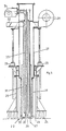
- 1 is an incinerator having a primary combustion chamber 2, 3. This is provided at its top with an outlet passage 63 leading to a secondary combustion chamber, not illustrated, which may advantageously be thermally separated from the primary combustion chamber and may e.g. be constructed as disclosed in U.S.-A-3,670,667.
- the arrangement of the secondary combustion chamber does not form part of the invention.
- the primary combustion chamber has a bottom section 2 of a size sufficient for receiving and burning the content of a barrel in solid state. Above the bottom section the combustion chamber has a top section 3 in which there is provided a lateral port 4 adapted to be closed by means of a vertically slidable gate 5 separating the combustion chamber from a sluice chamber 6 which has a bottom opening 7.
- a roller conveyor 51 which conveys barrels 8 standing on pallets 9 to an elevator 10 located directly below the bottom opening 7 of the sluice chamber 7.
- an elevator 10 located directly below the bottom opening 7 of the sluice chamber 7.
- this can lift the barrel up through the opening 7 and into the sluice chamber 6 until the pallet strikes the bottom of the sluice chamber and thereby engages the edge of the opening 7 to form a closure.
- a lifting and conveying fork 11 which by means of rollers 12 is rollably suspended from a guide rail 13 and is operable in such a manner that it can lift a barrel 8 introduced into the sluice chamber 7 from its pallet 9 and then push it in through the port 4 after the gate 5 has been lifted.
- the barrel holder is mounted in alignment with the port 4.
- the barrel holder is in the form of a cage formed by cooling pipes 15 which are extended out of an opening 16 of the wall of the combustion chamber and outside the latter are connected with a drum-shaped hub member 17 which is rotatably mounted in bearings and is sealed against the opening 16 by means of a sealing member 20.
- the barrel holder is thereby rotatable about a horizontal axis. During operation it is cooled by means of liquid supplied to the pipes 15 in any suitable manner, not illustrated, for circulation therein.
- the cage forming the barrel holder 14 has a gap 21 through which a barrel standing on the lifting and conveying fork 11 can be introduced into the cage and can then by lowering and withdrawal of the fork be left behind on pipes 15a forming the bottom of the cage.
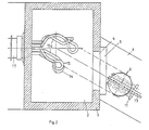
- the gap 21 is for simplicity of illustration shown as being directed coaxially with the axis of rotation of the barrel holder, and the same therefore applies to the port 4 of the combustion chamber and the sluice chamber 6 with the guide rail 13 forthe lifting and conveying fork 11. It is, however, more practical, as illustrated in Fig. 2, to arrange the gap 21, the port 4 and the sluice chamber 6 along an axis inclined in a horizontal plane with respect to the axis of rotation of the barrel holder 14.
- burner unit 22 with associated air injection means in the following referred to as the barrel burner.
- Further burners and air injection nozzles with associated blowers are provided at suitable locations and in a suitable number, including burners 38 (one of which is shown in Fig. 1) directed downwards at an inclination towards the outer surface of a barrel standing in the barrel holder, at least one burner 39 in the bottom section 2 of the combustion chamber, and a diagrammatically indicated blower 40 for the injection of air into the bottom section.
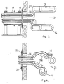
- FIG. 5 A preferred constructional form of the barrel burner 22 is shown in Fig. 5.
- the barrel burner is vertically displaceably mounted in spindle feed guides 23 carried by a frame 25 mounted on top of the upper wall 24 of the combustion chamber 2, 3.
- the barrel burner extends through an opening 26 of the upper wall 24 and has an outer tube 27, to which air is supplied from a blower 28 at the top.
- the lower portion 29 of the tube 27 consists of fireproof material and is constructed with passages 30 for injecting air into the combustion chamber in a downwardly and outwardly inclined direction.
- Inside the outer tube there is provided an intermediary tube 31 for conducting surplus air to an outlet tube 32 provided at the top of the burner unit.
- a control throttle is provided by means of which the pressure in the injection passages 30 can be controlled.
- the barrel burner also has an inner tube 33 with conduits for the supply of fuel from a fuel pump 34 to a fuel nozzle 35 and for the supply of water to an atomizing nozzle 36.
- the barrel burner is provided with a sensor 37, which is illustrated here in the form of a mechanical sensor connected with a suitable dynamometer.
- the barrel burner can be displaced from a position above the open top of a barrel standing in the barrel holder practically down to the bottom of the barrel.
- the sensor 37 serves to test whether the barrel burner on its way into and down through the barrel meets hard or liquid surfaces, and also to test whether the barrel burner in its downward travel reaches the bottom of the barrel as an indication that all waste has been burnt.
- a purely mechanical sensor it is possible to use a combined mechanical and thermal sensor, an infrared radiation sensor or other forms of sensors capable of performing the tests described.
- the incinerator is moreover provided with measuring equipment, control means, a program unit for automatically controlling the progress of the process.
- the plant is started up by means of the burners of the primary combustion chamber 2, 3 and the secondary combustion chamber (not illustrated) and is heated by means of these burners to the operation temperature.
- the barrel burner 22 is moved slowly down towards the open top of the barrel.
- the barrel burner is also provided with air injection passages for injecting air at an inclination downwards and outwards.
- the surface of the waste is subjected to heat from the flame of the burner, while at the same time combustion air is blown onto the surface, and an intensive combustion is initiated in the surface of the waste material in the barrel.
- the sensor 37 of the barrel burner is capable of testing whether the surface of the waste is hard as a crust or liquid.
- the speed of downward travel of the barrel burner 22 and the supply of injected air are controlled partly by this sensing of the nature of the waste, and partly by the combustion temperatures in the secondary combustion chamber and in the primary combustion chamber 2, 3.
- the barrel burner 22 continues to travel downwards in time with the combustion of the liquid until the waste in the barrel is completely burnt away and the bottom has been reached. Thereafter the barrel burner 22 is moved back to its top position whereafter, if deemed necessary, the barrel is turned 180° by means of the barrel holder in order to pour out any ashes, and then the barrel is turned back to upright position.
- the port 4 is opened and the lifting and conveying fork 11 is pushed in under the empty barrel standing in the barrel holder 14 and is then withdrawn to retract the barrel through the port 4 which is then again closed.
- the lifting and conveying fork deposes the empty barrel on the pallet 9 and the elevator 10 now lowers the empty barrel down onto a roller conveyor 52 for receiving and removing the empty barrels.
- the barrel burner 22 is immediately moved back to its top position and thereafter the barrel holder 14 is turned slowly around its axis of rotation. Under the influence of the oil burners in the walls of the combustion chamber, particularly the burners 38 directed downwards and inwards at an inclination, the first waste is burnt free from the inner walls of the barrel.
- the barrel holder 14 has turned the barrel 180°, or even before, the contents will drop out down into the bottom section of the combustion chamber which is constructed in conventional manner as a combustion furnace, and the burning of the solid waste is now completed in this part of the incinerator, which may be constructed substantially as described in U.S.-A-3,670,667.
- the barrel holder 14 now again turns the barrel to upright position with the opening at the top, whereafter the barrel burner 22 is again moved down and the sensor 37 tests whether the barrel is in fact empty. If this is not the case, the barrel burner 22 is withdrawn once more and the barrel holder 14 thereafter turns the barrel 180° to inverted position a second time so that the barrel may be completely emptied.
- the barrel burner 22 When the barrel burner 22 has ascertained by means of the sensor 37 that the barrel is in fact empty, the barrel is extracted and deposed on the roller conveyor 52 in the same manner as previously described. Thereafter the incinerator is ready for receiving and handling the next barrel in the same manner as described above.
- the barrel holder may be turned somewhat more than 90° in the direction opposite to that normally used for dropping out the contents, whereby the barrel is caused to slide out of the barrel holder and drop down onto the bottom of the combustion chamber, where it is then burnt.
- the construction of the apparatus may be varied in a multitiude of ways.
- fireproof materials may be used for the barrel holder 14 instead of cooling pipes.
- the incinerator may in well known manner be provided with a smoke neutralization system and a chimney with a smoke exhaust.
- the incinerator may in well known manner be provided with apparatus for the recovery of waste heat.
- the incinerator is particularly suitable for installation on the premises of the factory, in which the waste is produced. Thereby external transportation of the barrels is avoided and recovery of waste heat can take place within the factory itself.
- two or more barrel holders and associated equipment may be mounted side by side.
- the bottom section of the combustion chamber may be so constructed and provided with a separate sluice port in such a manner that the incinerator may alternatively be used for the incineration of other types of waste material or refuse than that mentioned above, according to well-known principles.
Landscapes
- Engineering & Computer Science (AREA)
- Environmental & Geological Engineering (AREA)
- Mechanical Engineering (AREA)
- General Engineering & Computer Science (AREA)
- Incineration Of Waste (AREA)
- Gasification And Melting Of Waste (AREA)
Claims (4)
Priority Applications (1)
| Application Number | Priority Date | Filing Date | Title |
|---|---|---|---|
| AT81903139T ATE12980T1 (de) | 1980-10-29 | 1981-10-28 | Ofen zum verbrennen von in faessern gespeicherten chemischen abfaellen. |
Applications Claiming Priority (2)
| Application Number | Priority Date | Filing Date | Title |
|---|---|---|---|
| DK4590/80 | 1980-10-29 | ||
| DK459080A DK459080A (da) | 1980-10-29 | 1980-10-29 | Fremgangsmaade og anlaeg til forbraending af kemisk affald lagret i fade |
Publications (2)
| Publication Number | Publication Date |
|---|---|
| EP0063597A1 EP0063597A1 (de) | 1982-11-03 |
| EP0063597B1 true EP0063597B1 (de) | 1985-04-24 |
Family
ID=8134927
Family Applications (2)
| Application Number | Title | Priority Date | Filing Date |
|---|---|---|---|
| EP81109121A Pending EP0051269A1 (de) | 1980-10-29 | 1981-10-28 | Ofen zum Verbrennen von mit chemischen Abfällen gefüllten Fässern |
| EP81903139A Expired EP0063597B1 (de) | 1980-10-29 | 1981-10-28 | Ofen zum verbrennen von in fässern gespeicherten chemischen abfällen |
Family Applications Before (1)
| Application Number | Title | Priority Date | Filing Date |
|---|---|---|---|
| EP81109121A Pending EP0051269A1 (de) | 1980-10-29 | 1981-10-28 | Ofen zum Verbrennen von mit chemischen Abfällen gefüllten Fässern |
Country Status (7)
| Country | Link |
|---|---|
| US (1) | US4419943A (de) |
| EP (2) | EP0051269A1 (de) |
| JP (1) | JPS57501647A (de) |
| CA (1) | CA1180602A (de) |
| DK (1) | DK459080A (de) |
| ES (1) | ES8206807A1 (de) |
| WO (1) | WO1982001581A1 (de) |
Families Citing this family (27)
| Publication number | Priority date | Publication date | Assignee | Title |
|---|---|---|---|---|
| FI85759C (fi) * | 1985-10-03 | 1992-05-25 | Outokumpu Oy | Avfallshanteringssaett. |
| US5005496A (en) * | 1988-07-07 | 1991-04-09 | Kyoei Steel Ltd. | Method for disposal of medical waste materials |
| US4969407A (en) * | 1988-11-23 | 1990-11-13 | Cadence Chemical Resources, Inc. | Containerized hazardous waste homogenate |
| US5224433A (en) * | 1988-11-23 | 1993-07-06 | Cadence Chemical Resources, Inc. | Waste fuel delivery to long kilns |
| US4974529A (en) * | 1988-11-23 | 1990-12-04 | Cadence Chemical Resources, Inc. | Method for energy recovery from containerized hazardous waste |
| US4930965A (en) * | 1988-11-23 | 1990-06-05 | Cadence Chemical Resources, Inc. | Apparatus for charging solid fuel to rotary kilns |
| US5058513A (en) * | 1988-11-23 | 1991-10-22 | Benoit Michael R | Energy recovery from containerized waste |
| US5083516A (en) * | 1988-11-23 | 1992-01-28 | Cadence Chemical Resources, Inc. | Processed wastes as supplemental fuel for modified cement films |
| KR950002639B1 (ko) * | 1988-11-23 | 1995-03-23 | 카덴스 에바이론멘탈 에너지, 인코포레이티드 | 환경보존적인 고체 폐기물 처리와 이것을 행하기 위한 개선된 습식 또는 건식처리 회전식 건조로 |
| US4951583A (en) * | 1989-07-27 | 1990-08-28 | Mcgill Environmental Systems, Inc. | Thermal destruction system for toxic substances |
| US5078594A (en) * | 1991-01-28 | 1992-01-07 | Cadence Chemical Resources, Inc. | Device for charging combustible solids to rotary kilns |
| US5226774A (en) * | 1991-01-28 | 1993-07-13 | Cadence Chemical Resources, Inc. | Device for charging combustible solids to rotary kilns |
| US5224118A (en) * | 1992-07-27 | 1993-06-29 | Murry Vance | On-site, biohazardous waste disposal system |
| US5333146A (en) * | 1992-07-27 | 1994-07-26 | Murry Vance | On-site, biohazardous waste disposal system |
| US5410121A (en) * | 1994-03-09 | 1995-04-25 | Retech, Inc. | System for feeding toxic waste drums into a treatment chamber |
| US5675056A (en) * | 1995-03-09 | 1997-10-07 | Vance; Murray A. | Incandescent waste disposal system and method |
| US5549058A (en) * | 1995-04-10 | 1996-08-27 | Cadence Environmental Energy, Inc. | Method and apparatus for charging a bulk material supplemental fuel into a long cement kiln |
| DK171956B1 (da) * | 1995-06-23 | 1997-08-25 | Carbo Consult Ltd | Fremgangsmaade til behandling af problematisk organisk kemisk affald samt anlaeg til brug ved fremgangsmaaden |
| US5816795A (en) * | 1996-05-24 | 1998-10-06 | Cadence Environmental Energy, Inc. | Apparatus and method for providing supplemental fuel to a preheater/precalciner kiln |
| US6325967B1 (en) | 1998-03-27 | 2001-12-04 | Material Resource Recovery Srbp Inc. | Incineration process |
| JP2000102874A (ja) * | 1998-09-30 | 2000-04-11 | Matsushita Electric Ind Co Ltd | 廃棄物の解体方法及びその装置 |
| MXPA02000864A (es) | 1999-07-27 | 2002-10-23 | Ash Grove Cement Co | Termolisis controlada de combustible solido en hornos precalentadores/precalcinados. |
| US7491861B2 (en) * | 2002-07-31 | 2009-02-17 | Studsvik, Inc. | In-drum pyrolysis |
| FR3005831B1 (fr) | 2013-05-21 | 2016-02-12 | Ingredia | Procede de fabrication d'un fromage et fromage obtenu |
| CN109573573A (zh) * | 2019-01-25 | 2019-04-05 | 宁波大地化工环保有限公司 | 一种全自动桶装进料装置 |
| CN110006047B (zh) * | 2019-03-27 | 2024-05-28 | 湖南人文科技学院 | 垃圾焚化装置及垃圾气化焚化炉 |
| US11565288B2 (en) * | 2020-04-10 | 2023-01-31 | Studsvik, Inc. | Systems, apparatuses, and methods for in-container waste treatment |
Family Cites Families (5)
| Publication number | Priority date | Publication date | Assignee | Title |
|---|---|---|---|---|
| US2822160A (en) * | 1954-08-16 | 1958-02-04 | Nat Furnace Corp | Furnace for cleaning containers |
| US3670667A (en) * | 1970-04-24 | 1972-06-20 | Bent Faurholdt | Incinerator for the combustion of waste products, particularly plastic materials |
| DE2251007C2 (de) * | 1972-10-18 | 1984-09-27 | Kernforschungszentrum Karlsruhe Gmbh, 7500 Karlsruhe | Veraschungsofen für radioaktive Abfälle |
| JPS537985A (en) * | 1976-07-12 | 1978-01-24 | Sumitomo Durez Co | Incireration furnace and method of wastes contained in vessel |
| US4332626A (en) * | 1979-09-04 | 1982-06-01 | Ppg Industries, Inc. | Method for removing liquid residues from vessels by combustion |
-
1980
- 1980-10-29 DK DK459080A patent/DK459080A/da not_active Application Discontinuation
-
1981
- 1981-10-27 CA CA000388836A patent/CA1180602A/en not_active Expired
- 1981-10-28 JP JP56503537A patent/JPS57501647A/ja active Pending
- 1981-10-28 EP EP81109121A patent/EP0051269A1/de active Pending
- 1981-10-28 US US06/387,872 patent/US4419943A/en not_active Expired - Fee Related
- 1981-10-28 WO PCT/DK1981/000095 patent/WO1982001581A1/en not_active Ceased
- 1981-10-28 EP EP81903139A patent/EP0063597B1/de not_active Expired
- 1981-10-28 ES ES506634A patent/ES8206807A1/es not_active Expired
Also Published As
| Publication number | Publication date |
|---|---|
| ES506634A0 (es) | 1982-08-16 |
| DK459080A (da) | 1982-04-30 |
| WO1982001581A1 (en) | 1982-05-13 |
| JPS57501647A (de) | 1982-09-09 |
| CA1180602A (en) | 1985-01-08 |
| ES8206807A1 (es) | 1982-08-16 |
| EP0063597A1 (de) | 1982-11-03 |
| EP0051269A1 (de) | 1982-05-12 |
| US4419943A (en) | 1983-12-13 |
Similar Documents
| Publication | Publication Date | Title |
|---|---|---|
| US4419943A (en) | Incinerator for chemical waste material stored in barrels | |
| CA1067346A (en) | Incinerator for refuse in containers | |
| EP0235369B1 (de) | Rauchverbrennungsanlage | |
| US5207176A (en) | Hazardous waste incinerator and control system | |
| US7798077B2 (en) | Freefall pyrolytic oven | |
| CA1103522A (en) | Method and apparatus for removal of fly ash from a waste incinerator with liquid slag discharge | |
| WO2010053381A1 (en) | Pyrolytic rendering of organic material | |
| US3561378A (en) | Incinerator for treating both liquid and solid material | |
| HUT65602A (en) | Apparatus for using hayardous waste to form non-hazardous aggregate | |
| US3457883A (en) | Incinerators and methods of incineration | |
| US4974527A (en) | Mobile incinerator system for low level radioactive solid waste | |
| US5416792A (en) | Preheat system | |
| US4976209A (en) | Furnaces for incinerating waste material | |
| US8006631B2 (en) | Radioactive waste reprocessing method and device | |
| US3765346A (en) | Ash processing system | |
| CN100489391C (zh) | 焚烧圆桶内收容的废弃物的装置及该方法 | |
| CN204629502U (zh) | 一种焚烧炉及移动式焚烧站 | |
| KR101028862B1 (ko) | 냉각수에 의한 2차 오염을 방지할 수 있는 연속식 소각로 | |
| KR950013974B1 (ko) | 유해성 폐기물을 무해성 혼합재로 만들기 위한 방법 및 그의 장치 | |
| JPH0868524A (ja) | 有機溶剤含有廃棄物の乾留焼却処理方法及び装置 | |
| KR102842140B1 (ko) | 체인터널형 폭발성 물질 소각시설 | |
| US7647874B2 (en) | Energy and steel recovery system | |
| US3714912A (en) | Incinerator | |
| JP3955564B2 (ja) | 小型ガス化焼却炉 | |
| JPH08189629A (ja) | ドラム缶の廃油脂類焼却装置 |
Legal Events
| Date | Code | Title | Description |
|---|---|---|---|
| PUAI | Public reference made under article 153(3) epc to a published international application that has entered the european phase |
Free format text: ORIGINAL CODE: 0009012 |
|
| 17P | Request for examination filed |
Effective date: 19820707 |
|
| AK | Designated contracting states |
Designated state(s): AT BE CH DE FR GB IT LI LU NL SE |
|
| XX | Miscellaneous (additional remarks) |
Free format text: VERBUNDEN MIT 81109121.4 (EUROPAEISCHE ANMELDENUMMER) DURCH ENTSCHEIDUNG VOM 16.05.83. |
|
| RBV | Designated contracting states (corrected) |
Designated state(s): AT BE CH DE FR GB IT LI LU NL SE |
|
| ITF | It: translation for a ep patent filed | ||
| GRAA | (expected) grant |
Free format text: ORIGINAL CODE: 0009210 |
|
| RAP1 | Party data changed (applicant data changed or rights of an application transferred) |
Owner name: APS CURANUM ENGINEERING CO. AF 1984 |
|
| RIN1 | Information on inventor provided before grant (corrected) |
Inventor name: FAURHOLDT, BENT |
|
| AK | Designated contracting states |
Designated state(s): AT BE CH DE FR GB IT LI LU NL SE |
|
| REF | Corresponds to: |
Ref document number: 12980 Country of ref document: AT Date of ref document: 19850515 Kind code of ref document: T |
|
| XX | Miscellaneous (additional remarks) |
Free format text: VERBUNDEN MIT 81109121.4 (EUROPAEISCHE ANMELDENUMMER) DURCH ENTSCHEIDUNG VOM 16.05.83. |
|
| REF | Corresponds to: |
Ref document number: 3170176 Country of ref document: DE Date of ref document: 19850530 |
|
| ET | Fr: translation filed | ||
| PG25 | Lapsed in a contracting state [announced via postgrant information from national office to epo] |
Ref country code: LU Free format text: LAPSE BECAUSE OF NON-PAYMENT OF DUE FEES Effective date: 19851031 |
|
| PGFP | Annual fee paid to national office [announced via postgrant information from national office to epo] |
Ref country code: NL Payment date: 19851031 Year of fee payment: 5 Ref country code: AT Payment date: 19851031 Year of fee payment: 5 |
|
| PLBE | No opposition filed within time limit |
Free format text: ORIGINAL CODE: 0009261 |
|
| STAA | Information on the status of an ep patent application or granted ep patent |
Free format text: STATUS: NO OPPOSITION FILED WITHIN TIME LIMIT |
|
| 26N | No opposition filed | ||
| PG25 | Lapsed in a contracting state [announced via postgrant information from national office to epo] |
Ref country code: AT Effective date: 19861028 |
|
| PG25 | Lapsed in a contracting state [announced via postgrant information from national office to epo] |
Ref country code: SE Effective date: 19861029 |
|
| PG25 | Lapsed in a contracting state [announced via postgrant information from national office to epo] |
Ref country code: LI Effective date: 19861031 Ref country code: CH Effective date: 19861031 Ref country code: BE Effective date: 19861031 |
|
| BERE | Be: lapsed |
Owner name: APS CURANUM ENGINEERING CO. AF 1984 Effective date: 19861031 |
|
| PG25 | Lapsed in a contracting state [announced via postgrant information from national office to epo] |
Ref country code: NL Effective date: 19870501 |
|
| NLV4 | Nl: lapsed or anulled due to non-payment of the annual fee | ||
| PG25 | Lapsed in a contracting state [announced via postgrant information from national office to epo] |
Ref country code: FR Free format text: LAPSE BECAUSE OF NON-PAYMENT OF DUE FEES Effective date: 19870630 |
|
| REG | Reference to a national code |
Ref country code: CH Ref legal event code: PL |
|
| GBPC | Gb: european patent ceased through non-payment of renewal fee | ||
| PG25 | Lapsed in a contracting state [announced via postgrant information from national office to epo] |
Ref country code: DE Effective date: 19870701 |
|
| REG | Reference to a national code |
Ref country code: FR Ref legal event code: ST |
|
| PG25 | Lapsed in a contracting state [announced via postgrant information from national office to epo] |
Ref country code: GB Effective date: 19881121 |
|
| EUG | Se: european patent has lapsed |
Ref document number: 81903139.4 Effective date: 19870812 |