EP0063625A1 - Procédé et dispositif pour polir des échantillons métallographiques - Google Patents
Procédé et dispositif pour polir des échantillons métallographiques Download PDFInfo
- Publication number
- EP0063625A1 EP0063625A1 EP81103154A EP81103154A EP0063625A1 EP 0063625 A1 EP0063625 A1 EP 0063625A1 EP 81103154 A EP81103154 A EP 81103154A EP 81103154 A EP81103154 A EP 81103154A EP 0063625 A1 EP0063625 A1 EP 0063625A1
- Authority
- EP
- European Patent Office
- Prior art keywords
- grinding
- grinding wheel
- metal sample
- sample
- clamp holder
- Prior art date
- Legal status (The legal status is an assumption and is not a legal conclusion. Google has not performed a legal analysis and makes no representation as to the accuracy of the status listed.)
- Withdrawn
Links
- 238000000034 method Methods 0.000 title claims abstract description 19
- 238000005498 polishing Methods 0.000 title 1
- 239000002826 coolant Substances 0.000 claims abstract description 12
- 239000002344 surface layer Substances 0.000 claims abstract description 4
- 239000002184 metal Substances 0.000 claims description 36
- 230000001681 protective effect Effects 0.000 claims description 7
- 238000005266 casting Methods 0.000 description 4
- 239000007788 liquid Substances 0.000 description 4
- 238000002604 ultrasonography Methods 0.000 description 4
- 238000001816 cooling Methods 0.000 description 3
- 239000000498 cooling water Substances 0.000 description 3
- 229910001208 Crucible steel Inorganic materials 0.000 description 1
- 229910000831 Steel Inorganic materials 0.000 description 1
- 238000005299 abrasion Methods 0.000 description 1
- 239000000654 additive Substances 0.000 description 1
- 230000000694 effects Effects 0.000 description 1
- 238000010891 electric arc Methods 0.000 description 1
- 230000005484 gravity Effects 0.000 description 1
- 238000003780 insertion Methods 0.000 description 1
- 230000037431 insertion Effects 0.000 description 1
- 230000001788 irregular Effects 0.000 description 1
- 239000000314 lubricant Substances 0.000 description 1
- 239000000463 material Substances 0.000 description 1
- 239000000203 mixture Substances 0.000 description 1
- 230000000737 periodic effect Effects 0.000 description 1
- 238000010079 rubber tapping Methods 0.000 description 1
- 238000005070 sampling Methods 0.000 description 1
- 238000007711 solidification Methods 0.000 description 1
- 230000008023 solidification Effects 0.000 description 1
- 238000010183 spectrum analysis Methods 0.000 description 1
- 239000010959 steel Substances 0.000 description 1
Images

Classifications
-
- B—PERFORMING OPERATIONS; TRANSPORTING
- B24—GRINDING; POLISHING
- B24B—MACHINES, DEVICES, OR PROCESSES FOR GRINDING OR POLISHING; DRESSING OR CONDITIONING OF ABRADING SURFACES; FEEDING OF GRINDING, POLISHING, OR LAPPING AGENTS
- B24B7/00—Machines or devices designed for grinding plane surfaces on work, including polishing plane glass surfaces; Accessories therefor
- B24B7/10—Single-purpose machines or devices
- B24B7/16—Single-purpose machines or devices for grinding end-faces, e.g. of gauges, rollers, nuts, piston rings
-
- B—PERFORMING OPERATIONS; TRANSPORTING
- B24—GRINDING; POLISHING
- B24B—MACHINES, DEVICES, OR PROCESSES FOR GRINDING OR POLISHING; DRESSING OR CONDITIONING OF ABRADING SURFACES; FEEDING OF GRINDING, POLISHING, OR LAPPING AGENTS
- B24B1/00—Processes of grinding or polishing; Use of auxiliary equipment in connection with such processes
Definitions
- the invention relates to a method for grinding metal samples by means of a rotating grinding wheel, in which the metal sample is moved periodically relative to the grinding wheel through the grinding area of the grinding wheel, in which the grinding wheel and the metal sample are preferably when the metal sample is outside the grinding area of the grinding wheel , experience an infeed movement in relation to one another, and in which a coolant is supplied to the metal sample.
- the metal specimens to be ground are in particular those which are taken from the casting ladle before casting in order to determine whether the casting has the correct composition. Such a sampling is common and necessary, especially for cast steel. The samples are taken in the liquid state and oxidize on solidification. However, a pure metal surface must be available for the analysis. For this reason, the samples are ground on one side. The ground surface is included in a spark gap, with the light of the spark or arc discharge in an analyzer is subjected to a spectral analysis. This ensures a very quick analysis.
- the sample must not become too hot due to the grinding, because it should be introduced into the analyzer by hand immediately after grinding.
- the repetition frequency with which the grinding area of the grinding wheel is traversed and / or the feed stroke must be kept relatively low and that the sample must be cooled with a liquid coolant during the entire grinding process.
- the grinding times achieved so far under this condition are relatively long and are around 50 to 60 seconds.
- the fact that the liquid coolant acts like a lubricant and reduces the effectiveness of the grinding wheel has an even longer effect on the grinding time per sample.
- the abrasion on the grinding wheel is not or hardly reduced by the liquid coolant, so that a relatively frequent change in relation to the number of samples ground of grinding wheels is necessary.
- changing the grinding wheel is associated with a loss of time.
- the invention has for its object to reduce the grinding time for each sample and also the loss time associated with a wheel change, based on "the number of samples that can be ground with a grinding wheel.
- the object is achieved in that the coolant is supplied only at the end of the grinding process, preferably the last time through the grinding area, and in that each time the grinding area is passed through, a surface layer is ground away from the metal sample at least to the depth to which the through Heat has penetrated during the previous passage through the grinding area.
- the invention is based on the following surprising consideration: the grinding heat spreads in the metal sample at a finite speed.
- the infeed stroke and / or the repetition frequency for passing through the grinding area can be selected accordingly. Cooling is only required at the end of the grinding process. This means that "dry” grinding can be carried out almost throughout the entire grinding process. This ensures great effectiveness the grinding wheel, which grinds a maximum of material away from the surface of the sample to be ground. As a result, the sample can be ground in a relatively short time.
- the invention further relates to a device for grinding metal samples, which works according to the method described above.
- a device for grinding metal samples, which works according to the method described above.
- a grinding wheel preferably a cup grinding wheel, which is connected to a rotary drive and a feed drive, with an adjustable clamp holder for the metal sample, with a swivel arm carrying the clamp holder, which is provided with a swivel drive and parallel to the grinding surface of the grinding wheel can be pivoted back and forth in such a way that a metal sample held in the clamping holder is periodically passed through the grinding area of the grinding wheel and with a coolant supply.
- the swivel arm can be swiveled about a horizontal swivel axis. Accordingly, the grinding wheel is arranged so that its grinding surface is aligned vertically. Accordingly, the clamp holder also receives the metal sample in such a way that the bevel on the metal sample runs laterally, ie the bevel surface is vertical.
- the sample is attached to the clamp on the swivel arm by a sloping downward Sample input slot fed. The sample then falls against a stop and is then pressed against a reference surface by a piston. Then the sample is clamped in the clamp.
- the cup grinding wheel is moved from a retracted sample changing position at a relatively high infeed speed against a stop piston until it actuates a microswitch.
- the microswitch forms a position indicator that sends a switchover signal to the controller for the infeed drive when the grinding wheel has reached its grinding position.
- the control then causes the feed drive to advance the grinding wheel with a reduced feed stroke.
- the swivel arm is given a periodic swivel movement by the swivel drive and cooling water is fed to the sample.
- the known device has the further disadvantage that only samples with a specific coin-like shape can be used because of the input slot.
- the samples since the samples have to find their way to the clamp holder by gravity after being thrown into the insertion slot, there is no guarantee that they will always lie in the position in which a secure clamping is ensured. If a sample is not correctly seated in the clamp holder, re-tensioning by manual positioning is not possible; the entire grinding process must first be carried out before the device releases the sample through an output slot and the sample is fed into the input slot for re-clamping and repeating the grinding process can.
- the invention is therefore also based on the object of improving the known device in such a way that a secure clamping of samples of different shapes is always ensured.
- This part of the object is achieved in that the grinding surface of the grinding wheel is directed downward and the clamping bracket is designed so that it allows the metal sample to be picked up with the grinding side protruding upwards.
- the sample is inserted manually into the clamp holder in the device according to the invention. This allows a perfect clamping and - if necessary - readjustment, without having to go through the entire grinding process first.
- An expedient development can consist in that an access protection part in the form of a movable grille or a door is provided, that between a protective position in which it prevents manual access to the clamp holder and a release position in which it allows manual access to the clamp holder , is adjustable, and that a control circuit connected to the access protection part is provided for the clamping bracket, which allows only a low-pressure clamping of the clamping bracket in the release position of the access protection part and a powerful clamping in the protection position. This measure serves to prevent accidents, ie an operator cannot pinch his fingers in the clamping bracket.
- a further improvement of the known device can consist in the fact that the position indicator is a sound sensor arranged in the vicinity of the metal sample, in particular an ultrasound sensor, which reacts to the sound generated when the metal sample touches the rotating grinding wheel.
- the use of the sound sensor as a position indicator ensures that the grinding wheel can drive directly against the sample in rapid feed and not, as in the prior art, first have to start with the stop with a microswitch and only then be brought into the grinding position by pivoting the swivel arm to be able to. Accordingly, the grinding time is also reduced by using the sound sensor.
- a constructive realization of the horizontal arrangement of the grinding surface of the grinding wheel and the described arrangement of the clamping bracket in such a way that it can accommodate the metal sample with the bevelled side projecting upward, can, according to another development of the invention, consist of the swivel arm and the rotary drive and the Feed drive for the grinding wheel bearing rotating arm are arranged on a common vertical shaft, around which the swivel arm can be pivoted and on which the supporting arm can be axially displaced.
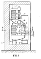
- the device shown in FIGS. 1 and 2 consists of a frame 1 which contains a vertical shaft 2.
- a support arm 3 is vertically slidably mounted.
- the support arm 3 is provided with a rotary drive 4 for a cup grinding wheel 5, which is arranged with its grinding surface 6 projecting downward.
- a feed drive 7 is also provided, by means of which the support arm 3 can be adjusted upwards and downwards.
- a pivot arm 8 is also mounted below the support arm 3 and can be pivoted back and forth about the shaft 2 by means of a pivot drive 9 (see FIG. 2).
- a clamping bracket 10 On the swivel arm 8 there is a clamping bracket 10 in the form of a chuck with two clamping jaws 11. The clamping jaws can be moved apart or against one another by a clamping drive 12. A metal sample 13 is clamped between the jaws 11.
- An ultrasonic sensor 14 is located on the clamping bracket 10, which is connected via a line 15 to a controller (not shown) for the feed drive 7.
- coolant supply pipes 16 and 17 attached, which are connected via hoses 18 and 19 to a cooling water source and a cooling air source.
- the two tubes 16, 17 have their outlet opening next to the metal sample 13.
- Figure 2 shows the pivot angle of the pivot arm 8.
- the sample 13 is guided periodically through the grinding area of the grinding wheel 6.
- One end position of the swivel arm 8 is in solid lines and the other swivel position is indicated in dash-dotted lines.
- the device is provided with an access protection door 2o, which is connected to a control, not shown, for the clamping drive 12.
- an access protection door 2o In the opening or release position of the protective door 2o, the clamping jaws 11 of the clamping bracket 1o can be moved towards each other, but only with so little pressure that it is not possible to pinch the fingers of the operating person.
- the access protection door 2o is closed, i.e. is in its protective position, the clamping jaws 11 of the clamping holder 10 can be moved against one another under pressure in order to clamp the metal sample.
- the operation of the device is as follows: Before a sample 13 is introduced into the device, the protective door 20 must be opened. The support arm 3 is in an upwardly withdrawn sample changing position. The sample 13 can now be inserted between the open jaws 11. By actuating an operating element, not shown, the clamping drive 12 can then be caused to move the clamping jaws 11 together with little pressure until they meet the sample 13. Then the protective door 2o closed, whereby, as described, the jaws 11 now clamp the sample 13 pressure-tight. At the same time, the control for the feed drive 7 is activated such that the support arm 3 is lowered relatively quickly.
- the swivel drive 9 is put into operation at the same time, whereby the swivel arm 8 is swiveled back and forth in the manner shown.
- the ultrasound sensor 14 responds to this ultrasound by supplying the control for the feed drive 7 with a changeover signal.
- the feed drive 7 now reduces the feed stroke.
- the feed drive 7 is a stepper motor which always lowers the support arm 3 by one step when the samples are outside the grinding area of the grinding wheel 5.
- the feed stroke is selected such that it grinds the zone of the metal sample 13 that has been heated by the last grinding period.
- the grinding surface of the sample 13 is cooled by cooling water or cooling air.
- the duration of the grinding process can be set selectively.
- the swivel drive 9 is switched off automatically.
- the swivel arm 8 remains in the position shown in solid lines in FIG. 2, in which the sample is accessible for removal.
- the coolant supply and the rotary drive 4 for the grinding wheel 5 are also switched off automatically. It is of course also possible to initiate this process manually. The latter may be desired if you find that the grind is unsatisfactory and that regrinding is still necessary.
- FIG. 3 A sample with a relatively irregular shape is shown in side view in FIG. Such a sample can be clamped without difficulty with the clamp holder shown.
- FIG. 3 also indicates how zones of equal thickness are ground off from the grinding surface of the sample on the top. The depth of cut is exaggerated here for a better understanding of the situation.
Landscapes
- Engineering & Computer Science (AREA)
- Mechanical Engineering (AREA)
- Sampling And Sample Adjustment (AREA)
Priority Applications (1)
| Application Number | Priority Date | Filing Date | Title |
|---|---|---|---|
| EP81103154A EP0063625A1 (fr) | 1981-04-27 | 1981-04-27 | Procédé et dispositif pour polir des échantillons métallographiques |
Applications Claiming Priority (1)
| Application Number | Priority Date | Filing Date | Title |
|---|---|---|---|
| EP81103154A EP0063625A1 (fr) | 1981-04-27 | 1981-04-27 | Procédé et dispositif pour polir des échantillons métallographiques |
Publications (1)
| Publication Number | Publication Date |
|---|---|
| EP0063625A1 true EP0063625A1 (fr) | 1982-11-03 |
Family
ID=8187679
Family Applications (1)
| Application Number | Title | Priority Date | Filing Date |
|---|---|---|---|
| EP81103154A Withdrawn EP0063625A1 (fr) | 1981-04-27 | 1981-04-27 | Procédé et dispositif pour polir des échantillons métallographiques |
Country Status (1)
| Country | Link |
|---|---|
| EP (1) | EP0063625A1 (fr) |
Cited By (3)
| Publication number | Priority date | Publication date | Assignee | Title |
|---|---|---|---|---|
| EP0283274A1 (fr) * | 1987-03-17 | 1988-09-21 | Sintobrator, Ltd. | Dispositif de polissage |
| CN114473809A (zh) * | 2021-12-09 | 2022-05-13 | 诸暨市理磊机械制造有限公司 | 一种自动换向及冷却的抛光机夹持系统 |
| CN115389540A (zh) * | 2022-08-25 | 2022-11-25 | 中核四0四有限公司 | 一种稀土金属镀层扫描电镜截面试样精密磨样装置及方法 |
Citations (9)
| Publication number | Priority date | Publication date | Assignee | Title |
|---|---|---|---|---|
| BE549314A (fr) * | 1955-07-08 | |||
| US1972086A (en) * | 1931-05-15 | 1934-09-04 | John P Buckley | Metallographic polishing machine |
| US2248262A (en) * | 1938-08-09 | 1941-07-08 | Black & Decker Mfg Co | Grinding valve stems and tappets |
| US2940226A (en) * | 1955-10-24 | 1960-06-14 | Bisterfeld & Stolting | Fusion abrading process for surfaceworking flat and curved surfaces of metal bodies and apparatus for carrying out said process |
| FR1259435A (fr) * | 1960-03-11 | 1961-04-28 | Machine à meuler les plaques minces pour l'examen microscopique de corps solides | |
| FR1394802A (fr) * | 1964-01-29 | 1965-04-09 | France Ministre Des Armees | Appareils pour le polissage mécanique des surfaces métalliques ou autres |
| FR1482161A (fr) * | 1966-04-13 | 1967-05-26 | Bull General Electric | Machines à polir des surfaces planes |
| US3392494A (en) * | 1964-12-01 | 1968-07-16 | Atomic Energy Commission | Grinding devices |
| US3452483A (en) * | 1965-11-29 | 1969-07-01 | Jobling & Co James A | Grinding machines |
-
1981
- 1981-04-27 EP EP81103154A patent/EP0063625A1/fr not_active Withdrawn
Patent Citations (9)
| Publication number | Priority date | Publication date | Assignee | Title |
|---|---|---|---|---|
| US1972086A (en) * | 1931-05-15 | 1934-09-04 | John P Buckley | Metallographic polishing machine |
| US2248262A (en) * | 1938-08-09 | 1941-07-08 | Black & Decker Mfg Co | Grinding valve stems and tappets |
| BE549314A (fr) * | 1955-07-08 | |||
| US2940226A (en) * | 1955-10-24 | 1960-06-14 | Bisterfeld & Stolting | Fusion abrading process for surfaceworking flat and curved surfaces of metal bodies and apparatus for carrying out said process |
| FR1259435A (fr) * | 1960-03-11 | 1961-04-28 | Machine à meuler les plaques minces pour l'examen microscopique de corps solides | |
| FR1394802A (fr) * | 1964-01-29 | 1965-04-09 | France Ministre Des Armees | Appareils pour le polissage mécanique des surfaces métalliques ou autres |
| US3392494A (en) * | 1964-12-01 | 1968-07-16 | Atomic Energy Commission | Grinding devices |
| US3452483A (en) * | 1965-11-29 | 1969-07-01 | Jobling & Co James A | Grinding machines |
| FR1482161A (fr) * | 1966-04-13 | 1967-05-26 | Bull General Electric | Machines à polir des surfaces planes |
Cited By (5)
| Publication number | Priority date | Publication date | Assignee | Title |
|---|---|---|---|---|
| EP0283274A1 (fr) * | 1987-03-17 | 1988-09-21 | Sintobrator, Ltd. | Dispositif de polissage |
| US4837979A (en) * | 1987-03-17 | 1989-06-13 | Sintobrator, Ltd. | Polishing device |
| CN114473809A (zh) * | 2021-12-09 | 2022-05-13 | 诸暨市理磊机械制造有限公司 | 一种自动换向及冷却的抛光机夹持系统 |
| CN114473809B (zh) * | 2021-12-09 | 2023-11-24 | 浙江启迪环保科技有限公司 | 一种自动换向及冷却的抛光机夹持系统 |
| CN115389540A (zh) * | 2022-08-25 | 2022-11-25 | 中核四0四有限公司 | 一种稀土金属镀层扫描电镜截面试样精密磨样装置及方法 |
Similar Documents
| Publication | Publication Date | Title |
|---|---|---|
| DE4311236A1 (de) | Automatische Rohrschneidevorrichtung | |
| EP0183812B1 (fr) | Appareil pour nettoyer la tuyere a gaz d'un chalumeau a souder | |
| DE2415105A1 (de) | Kernbohrmaschine fuer flachglas | |
| DE8030325U1 (de) | Vorrichtung zum bearbeiten von bremsscheiben | |
| DE1907803A1 (de) | Bohrer-Schleifgeraet | |
| DE102009019857A1 (de) | Trennvorrichtung | |
| DE3320283A1 (de) | Verfahren zum schneiden und vorrichtung zum steuern des saegebandvorschubes bei bandsaegemaschinen | |
| DE3821362C1 (en) | Apparatus for smoothing a mandrel bar | |
| WO1991014166A1 (fr) | Systeme de preparation d'echantillons de fer et d'acier | |
| DE3802582A1 (de) | Verfahren zum schneiden von betonteilen, insbesondere betonrohren, mit vorzugsweise grossem lichten durchmesser und vorrichtung zur durchfuehrung des verfahrens | |
| DE2854551A1 (de) | Maschine zum zerschneiden von stangen in scheiben | |
| DE2803645A1 (de) | Verfahren und vorrichtung zum fraesen von kurbelzapfen einer kurbelwelle | |
| DE3843647A1 (de) | Verfahren und vorrichtungen zum aufbringen geschmolzenen harten werkstoffs auf zaehne von schneidwerkzeugen | |
| DE3835780A1 (de) | Vorrichtung zum abrichten einer schleifscheibe | |
| DE2823479A1 (de) | Werkstueckauffangvorrichtung fuer drehautomaten | |
| DE4028372C1 (fr) | ||
| DE3216929A1 (de) | Vorrichtung zum entgraten von werkstuecken | |
| DE2212055B2 (de) | Vorrichtung zum Verschweißen von koaxial liegenden Rohren aus thermoplastischem Kunststoff | |
| EP0082487A2 (fr) | Dispositif pour enlever des bavures et des nopes sur des pneumatiques de dimensions différentes | |
| DE29705243U1 (de) | Schweißvorrichtung | |
| DE3542980A1 (de) | Verfahren und vorrichtung zum abtrennen des grates beim trennschneiden | |
| EP1060832A1 (fr) | Procédé et dispositif pour supporter des pièces en rectification coaxiale | |
| DE860885C (de) | Vorrichtung zum Umfangfraesen grosser Werkstuecke, insbesondere von Stahlingots | |
| DE3106234C2 (fr) | ||
| DE102006034207B3 (de) | Sägemaschine und Verfahren zum Zuschneiden von Werkstücken mittels einer solchen Sägemaschine |
Legal Events
| Date | Code | Title | Description |
|---|---|---|---|
| PUAI | Public reference made under article 153(3) epc to a published international application that has entered the european phase |
Free format text: ORIGINAL CODE: 0009012 |
|
| AK | Designated contracting states |
Designated state(s): BE CH DE FR GB IT NL SE |
|
| STAA | Information on the status of an ep patent application or granted ep patent |
Free format text: STATUS: THE APPLICATION IS DEEMED TO BE WITHDRAWN |
|
| 18D | Application deemed to be withdrawn |
Effective date: 19831012 |