EP0063662B1 - Vorgefertigte Einheit zur Herstellung eines Baugerüstes - Google Patents
Vorgefertigte Einheit zur Herstellung eines Baugerüstes Download PDFInfo
- Publication number
- EP0063662B1 EP0063662B1 EP81400652A EP81400652A EP0063662B1 EP 0063662 B1 EP0063662 B1 EP 0063662B1 EP 81400652 A EP81400652 A EP 81400652A EP 81400652 A EP81400652 A EP 81400652A EP 0063662 B1 EP0063662 B1 EP 0063662B1
- Authority
- EP
- European Patent Office
- Prior art keywords
- uprights
- crosspieces
- posts
- longitudinal
- articulated
- Prior art date
- Legal status (The legal status is an assumption and is not a legal conclusion. Google has not performed a legal analysis and makes no representation as to the accuracy of the status listed.)
- Expired
Links
Images

Classifications
-
- E—FIXED CONSTRUCTIONS
- E04—BUILDING
- E04B—GENERAL BUILDING CONSTRUCTIONS; WALLS, e.g. PARTITIONS; ROOFS; FLOORS; CEILINGS; INSULATION OR OTHER PROTECTION OF BUILDINGS
- E04B1/00—Constructions in general; Structures which are not restricted either to walls, e.g. partitions, or floors or ceilings or roofs
- E04B1/18—Structures comprising elongated load-supporting parts, e.g. columns, girders, skeletons
- E04B1/26—Structures comprising elongated load-supporting parts, e.g. columns, girders, skeletons the supporting parts consisting of wood
- E04B1/2604—Connections specially adapted therefor
- E04B2001/2616—Hinged connections of wooden members
-
- E—FIXED CONSTRUCTIONS
- E04—BUILDING
- E04B—GENERAL BUILDING CONSTRUCTIONS; WALLS, e.g. PARTITIONS; ROOFS; FLOORS; CEILINGS; INSULATION OR OTHER PROTECTION OF BUILDINGS
- E04B1/00—Constructions in general; Structures which are not restricted either to walls, e.g. partitions, or floors or ceilings or roofs
- E04B1/18—Structures comprising elongated load-supporting parts, e.g. columns, girders, skeletons
- E04B1/26—Structures comprising elongated load-supporting parts, e.g. columns, girders, skeletons the supporting parts consisting of wood
- E04B2001/2696—Shear bracing
Definitions
- the present invention relates to a prefabricated assembly which can be used to obtain, with limited and unskilled labor, the installation of a support structure.
- the invention relates more specifically to the establishment of structure or framework for the erection of walls intended for the manufacture of premises such as residential houses, scenerys, bungalows, light constructions, workshops, generally private or public premises.
- the invention essentially uses wooden frame elements formed of longitudinal elements pre-assembled by prefabrication and able to be stored and transported in the folded state, the longitudinal elements being parallel to each other; these elements are capable of being deployed in their final position in situ and assembled on site to obtain a support structure for vertical walls, walls, partitions, or horizontal, for example floor or ceiling or roof elements.
- these elements even if they are obtained by prefabrication, are made in their final dimension and are intended to be transported as such to be assembled on site at the place of construction; it follows that these elements, for example the load-bearing walls, are already provided with framework elements which must give their rigidity and their mechanical resistance to the assembly as well as the surfacing and coating elements; so that we obtain large prefabricated elements whose handling and installation require teams of several people and experienced staff if not very specialized.
- the invention aims to produce light framework elements which can be stored, sold, transported and brought on site in the folded position and which can therefore be transported by a limited number of people and reduced to a team of two workers, the elements are also likely to be deployed on site and brought into their position of use without requiring specialized professional work.
- the elements according to the invention combining the advantages of a prefabrication in the factory, therefore using elements produced in series and of limited cost price, as well as the advantages of a light assembly on site from a reduced team. and allowing rapid work, make it possible to considerably lower the cost price of constructions made from the elements of the invention and also open up to new layers of unskilled amateurs the possibilities of achieving a dwelling requiring no assistance or a very limited competition of professionals.
- German Patent No. 385,976 describes a collapsible structure formed of slats forming a foldable articulated cross and deployable to form a diamond trellis secured by vertical slats; this device makes it possible to constitute a fulcrum for a non-load-bearing wall but it is not sufficient to constitute itself a load-bearing structure, framework of a construction; in addition, it uses two types of elements, on the one hand the foldable spider and on the other hand the fixing slats which must be attached to each crossing of the slats, which involves considerable work.
- Dutch patent n ° 72 07690 provides a folding structure formed by a set of uprights assembled by a set of crosspieces which are common to all the uprights; the angular folding of the crosspieces brings the uprights one against the other, which results in a structure which remains bulky especially in length.
- British Patent No. 151,604 describes a construction in which the uprights are formed of twin posts joined by crosspieces; however, this patent does not provide for an assembly of the posts to form a deployable structure capable of passing by simple extension from a compacted position to a deployed position covering an entire surface.
- the invention relates to a prefabricated assembly for the erection of the vertical framework supporting a construction, in particular for the production of walls or partitions, of the type comprising uprights and side members, the uprights being able to be aligned vertically, in resting on a lower spar, forming a low sole, and supporting at their top an upper spar forming a high beam, in which the uprights are formed by two identical wooden posts of quadrangular section, twinned and joined by spacers and all the uprights and side members are provided with perforations made at modular intervals and forming a mortise, allowing the connection of the elements by insertion of a tenon or dowel in the mortises aligned between the elements to be assembled and characterized in that the uprights are assembled together , from prefabrication by crosspieces articulated by one end on an upright being inserted between the two posts the opposite end of each crosspiece being articulated on the neighboring upright, allowing the storage of the uprights, connected together by the articulated crosspieces, in
- Figure 2 we see a foldable frame for the establishment of a vertical wall such as a load-bearing wall or partition.
- the frame consists of a plurality of longitudinal elements arranged here vertically and each constituting an upright 1, 1 ', 2, 2'.
- crosspieces 3, 3 ', 4, 4', 5, 5 ' make it possible to ensure, by their articulation, the passage of the reinforcing element from a folded position which is shown on the left of FIG. 1 and from FIG. 3 to a deployed position which is represented on the right of FIG. 1 and of FIG. 3.
- the load-bearing reinforcement can therefore advantageously be produced with very light elements since it only comprises the framework, without any connection from the prefabrication stage with the surfacing and insulation elements; and this frame can be transported and stored in conditions requiring only a small footprint while brought on site it is quickly and error-free deployed and ready for assembly without calculations or measurements being necessary, the deployment ensuring the spacing necessarily correct amounts between them.
- the uprights are preferably produced in the form of two twin elements, for example two parallel posts 7 and 7 'together forming the upright 8, or 9, 9' forming by their assembly the upright 10.
- the two posts 7 and 7 ' are assembled by spacers 11, 11', 12 which are arranged along the length of the half uprights.
- the projecting end of the outer spacers is inserted between two parallel rails which constitute the connecting beams of the uprights in their assembly and mounting position.
- the lower spar 15 constitutes the lower sole and it assembles the uprights at their base, while the upper spar 16 constitutes the upper smooth and it ensures the connection to the top of the same uprights.
- the uprights brought into a suitable spacing position thanks to the articulated crosspieces are connected not only by said crosspieces but also by upper and lower beams thereby ensuring perfect cohesion of the frame obtained.
- the lower and upper rails respectively are themselves made up of two twin battens 36, 37, 39, 40 which are arranged at the same spacing as the posts so that the uprights are superimposed perpendicularly on the beams and the end spacer. respectively 13, 14, is thus inserted into the interior space which separates the parallel battens forming the spar.
- the locking of the end spacers 13 and 14 is obtained by bolting, keying or fitting a dowel.
- the side members have suitably spaced from the mortises while the end spacers of the uprights also include a mortise which is notably visible on the spacer 14 'of the upright 10; the spacing of the mortises 17, 17 ', 18, 18' of the longitudinal members is such that when the uprights are brought into the deployed position, the channels passing through the end spacers 13, 14 come into alignment with a corresponding perforation on the longitudinal member which which allows the installation of bolts ensuring the joining of the uprights and side members.
- the arms or crosspieces of the uprights consist of rods mounted at one end on a joint crossing the two twin elements of the upright.
- the supporting structure according to the invention allows the insertion of a frame, for example a window.
- the intermediate uprights are easily shifted from their normal place to separated positions, clearing the opening; all the uprights and crosspieces being made from wooden elements, it is easy to move these uprights by shortening the crosspieces to the appropriate length so as to ensure the positioning of the displaced uprights at the correct spacing necessary for the installation a frame and these posts or uprights remaining linked to the entire frame.
- a lintel respectively lower 22 and upper 23 can be inserted between the uprights and the legs 24, can advantageously reinforce the lower space separating the two lateral uprights below the frame intended to be put in place.
- exterior surfacing panels 28 for example plywood or fiber cement, as well as the interior wall 29, made of reinforced plaster, are put in place.
- Cross members forming bracing legs 42 will advantageously be placed diagonally using in particular the perforations 17, 17 'of the side members and / or uprights.
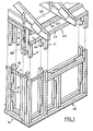
- Figure 1 shows a perspective view of a supporting frame of a construction seen from an outside angle.
- the left part of the figure shows the end of the load-bearing wall which can be built under the same conditions as the reinforcement shown in
- FIG. 4 the upright 10 being shown in the two figures, respectively 4 and 1.
- FIG. 1 illustrates a particular development of the invention and is constituted by a longitudinal lintel running either over the entire length of the load-bearing wall or at the level of the openings or frames requiring load recovery.
- the lintel 43 consists of two parallel vertical blades 44 and 44 'respectively, which rest on the end of the posts forming the bottom wall; for this purpose, each blade comprises towards the outside stiffening strips respectively upper 46 and lower 47; it can be seen in FIG. 1 that the cleat 47 and blade 44 'assembly rests on the end of the posts 10' and 8 'respectively.
- the symmetrical blade 44 is also associated with a lower cleat and an upper cleat resting on the posts of. amounts.
- the end spacer 50 belonging to the corner post 10 enters the interior space separating the two blades 44, 44' and also ensures their bracing.
- the lintel formed by the two blades 44, 44 ′ can advantageously and according to a characteristic of the invention, be reinforced by an inner fur disposed in the form of a wooden plank inserted longitudinally and parallel between the two blades thereby ensuring the reinforcement that may be necessary , for example in the case of construction in height, the wall having to support an upper floor.
- the lintel 43 can advantageously be itself surmounted by a spar identical to the spar 16 of FIG. 4 and constituted by two cleats or parallel rails held by the assembly plate 49.
- the lintel constitutes a particularly flexible complement since it can be used from the two parallel blades used alone or with an inner reinforcement fur; and the lintel can also be arranged either over the entire length of the construction, or over only a part of this length; the uprights being provided in the area not surmounted by the lintel, with a suitable height allowing them to catch up with the top rail 48, 49.
- the invention is not limited to a dimensioning and the reinforcing elements can be produced in any size and any dimension and they can thus be put in place for the construction of light constructions and of dimension reduced for example animal shelter, garden shed, etc.
- the invention also makes it possible to produce light cells which can be easily transported in volume for use as a shelter or a worksite hut.
- the invention makes it possible in particular to produce light constructions which are easily removable and which can thus be transported from one place to another, the reinforcing elements according to the invention then being returned to their folded position and allowing transport on volume. reduced.
Landscapes
- Engineering & Computer Science (AREA)
- Architecture (AREA)
- Physics & Mathematics (AREA)
- Electromagnetism (AREA)
- Civil Engineering (AREA)
- Structural Engineering (AREA)
- Load-Bearing And Curtain Walls (AREA)
- Bending Of Plates, Rods, And Pipes (AREA)
- Steering-Linkage Mechanisms And Four-Wheel Steering (AREA)
- Body Structure For Vehicles (AREA)
- Joining Of Building Structures In Genera (AREA)
Claims (6)
Priority Applications (3)
| Application Number | Priority Date | Filing Date | Title |
|---|---|---|---|
| AT81400652T ATE17267T1 (de) | 1981-04-24 | 1981-04-24 | Vorgefertigte einheit zur herstellung eines baugeruestes. |
| DE8181400652T DE3173350D1 (en) | 1981-04-24 | 1981-04-24 | Prefabricated unit for the realization of a construction frame |
| EP81400652A EP0063662B1 (de) | 1981-04-24 | 1981-04-24 | Vorgefertigte Einheit zur Herstellung eines Baugerüstes |
Applications Claiming Priority (1)
| Application Number | Priority Date | Filing Date | Title |
|---|---|---|---|
| EP81400652A EP0063662B1 (de) | 1981-04-24 | 1981-04-24 | Vorgefertigte Einheit zur Herstellung eines Baugerüstes |
Publications (2)
| Publication Number | Publication Date |
|---|---|
| EP0063662A1 EP0063662A1 (de) | 1982-11-03 |
| EP0063662B1 true EP0063662B1 (de) | 1986-01-02 |
Family
ID=8188508
Family Applications (1)
| Application Number | Title | Priority Date | Filing Date |
|---|---|---|---|
| EP81400652A Expired EP0063662B1 (de) | 1981-04-24 | 1981-04-24 | Vorgefertigte Einheit zur Herstellung eines Baugerüstes |
Country Status (3)
| Country | Link |
|---|---|
| EP (1) | EP0063662B1 (de) |
| AT (1) | ATE17267T1 (de) |
| DE (1) | DE3173350D1 (de) |
Families Citing this family (18)
| Publication number | Priority date | Publication date | Assignee | Title |
|---|---|---|---|---|
| FR2563855A1 (fr) * | 1984-05-07 | 1985-11-08 | Legrand Roland | Ossature en bois deployable. |
| DE8429902U1 (de) * | 1984-10-11 | 1985-04-11 | Kaiser, Karl, Dipl.-Ing., 7990 Friedrichshafen | Holzsbauteilesatz |
| US4781007A (en) * | 1985-11-07 | 1988-11-01 | Bianchi Jean Luc F | Deployable wooden ossature |
| US4790113A (en) * | 1986-02-18 | 1988-12-13 | Gregory Robert K | Adjustable depth truss |
| GB2188078B (en) * | 1986-03-18 | 1989-11-15 | Christopher Harraway Dawson | Cavity wall and building incorporating same |
| FR2650611A1 (fr) * | 1989-08-07 | 1991-02-08 | Muller Feuga Arnaud | Ossature en bois pour la realisation de murs ou parois d'une construction et construction obtenue a partir de ladite ossature |
| DE9319162U1 (de) * | 1993-11-25 | 1994-03-24 | Apart Mobil Mobilheimbau- und Vertriebsgesellschaft mbH, 46240 Bottrop | Transportable Wohneinheit |
| DE19963360C2 (de) * | 1999-02-03 | 2003-08-21 | Jochen Leserer | Verfahren zur Errichtung von Bauwerken mit niedrigen K-Werten |
| FR2795441B1 (fr) * | 1999-06-24 | 2002-01-04 | Gilbert Leon Roussel | Structure en pieces bois apparentes rainurees jumelees, poteaux poutres potelets, fixees par combinaison a l'aide d'elements d'assemblage en maintenant dans leurs profils des panneaux types |
| WO2002090680A1 (en) * | 2001-05-10 | 2002-11-14 | Oeveraas Knut | Erection system for the structure of a house |
| DE20303904U1 (de) * | 2003-03-12 | 2004-04-29 | Schmidt, Hermann | Bausatz zur Erzeugung eines Gebäudes |
| MY158546A (en) * | 2009-10-01 | 2016-10-14 | Univ Putra Malaysia | Architectonic spacer building system |
| AU2013304949C1 (en) | 2012-08-24 | 2020-12-24 | Novartis Ag | NEP inhibitors for treating diseases characterized by atrial enlargement or remodeling |
| WO2014120028A1 (en) | 2013-01-29 | 2014-08-07 | Ux2 Centrum Technologiczne Sp. Z.O.O. | The lock of the connection set for structural elements, the connection set with locks and the method of joining constructional elements with the use of the connection set |
| ITPR20130070A1 (it) * | 2013-09-18 | 2015-03-19 | Giuseppe Ricci | Un sistema costruttivo di strutture portanti, in legno, di edifici, e costruzione cosi' realizzata |
| CN108915123A (zh) * | 2018-06-22 | 2018-11-30 | 中国建筑设计院有限公司 | 一种免钉自固定隔断骨架 |
| CN109113750B (zh) * | 2018-10-30 | 2023-08-29 | 中铁第一勘察设计院集团有限公司 | 盾构端头加固失效的应急装置及其施工方法 |
| CN116748860B (zh) * | 2023-08-16 | 2023-11-21 | 湖南路桥建设集团有限责任公司 | 一种贝雷架快速搭接用校正机构及贝雷架快速搭接方法 |
Family Cites Families (9)
| Publication number | Priority date | Publication date | Assignee | Title |
|---|---|---|---|---|
| BE343137A (de) * | ||||
| GB151604A (en) * | 1919-09-27 | 1921-12-08 | Frank Archibald Palen | Improvements in and relating to building constructions |
| US1421299A (en) * | 1920-04-08 | 1922-06-27 | Frank A Palen | Building construction |
| DE385976C (de) * | 1920-10-23 | 1923-12-01 | Hans Zamecznik | Verfahren zur Herstellung des Traggerippes flaechenartiger Bauteile, wie Waende, Decken, Daecher |
| FR1003072A (fr) * | 1946-11-29 | 1952-03-13 | Krauth & Co | Procédé pour la fabrication de carcasses de maisons |
| FR2122749A5 (de) * | 1971-01-22 | 1972-09-01 | Avier Albert | |
| NL7207690A (de) * | 1972-06-07 | 1973-12-11 | ||
| FR2355630A1 (fr) * | 1976-04-28 | 1978-01-20 | Chedeau Philippe | Structure en bois autoporteuse |
| DE2825563A1 (de) * | 1978-06-10 | 1979-12-20 | Stanislaus Dipl Ing Malik | Bauholz |
-
1981
- 1981-04-24 AT AT81400652T patent/ATE17267T1/de not_active IP Right Cessation
- 1981-04-24 EP EP81400652A patent/EP0063662B1/de not_active Expired
- 1981-04-24 DE DE8181400652T patent/DE3173350D1/de not_active Expired
Also Published As
| Publication number | Publication date |
|---|---|
| EP0063662A1 (de) | 1982-11-03 |
| ATE17267T1 (de) | 1986-01-15 |
| DE3173350D1 (en) | 1986-02-13 |
Similar Documents
| Publication | Publication Date | Title |
|---|---|---|
| EP0063662B1 (de) | Vorgefertigte Einheit zur Herstellung eines Baugerüstes | |
| EP2347057B1 (de) | Modulares konstruktionssystem | |
| FR2613403A1 (fr) | Pilier, notamment pour constructions a ossature bois et constructions faisant usage de tels piliers | |
| BE1003666A3 (fr) | Ossature pour batiments. | |
| BE1011185A5 (fr) | Ossature de batiment. | |
| FR2468699A1 (fr) | Element repliable d'ossature pour la construction | |
| FR2584461A1 (fr) | Procede d'assemblage modulaire tridimensionnel demontable destine a tout type de construction | |
| FR2464339A1 (fr) | Systeme de construction d'une ossature de batiment par assemblage d'elements prefabriques en beton | |
| WO2016189210A1 (fr) | Bâtiment dont les composants sont majoritairement préfabriqués | |
| FR3122443A1 (fr) | Structure modulaire en béton de grande hauteur | |
| FR2532352A1 (fr) | Construction habitable individuelle en elements modulaires montee manuellement | |
| FR2534613A1 (fr) | Structure metallique de batiment | |
| EP0826840A1 (de) | Bauzelle | |
| FR2486565A1 (fr) | Ossature industrialisee destinee a la construction et au contreventement de parois | |
| FR2894265A1 (fr) | Systeme de structure modulaire appliquee a une construction a ossature | |
| WO1996034158A1 (fr) | Panneau composite, assemblage de panneaux et batiment de type prefabrique construit a l'aide de tels panneaux | |
| EP0365512A1 (de) | Vorgefertigte Bauelemente zur Errichtung von Gebaüden und Bauverfahren zur Errichtung von Gebaüden mittels dieser Bauelemente | |
| FR2572106A1 (fr) | Procede de construction de pignons pour edifices de grande hauteur et les moyens de mise en oeuvre du procede | |
| FR2656355A1 (fr) | Pilier et constructions, notamment a ossature bois, utilisant un tel pilier. | |
| EP4636182A1 (de) | Metallrahmen für wohngebäude wie wohnhaus | |
| EP4610445A1 (de) | Modulare einheit, die dazu bestimmt ist, mindestens einen teil einer gebäudefassade zu bilden | |
| FR2898918A1 (fr) | Edifice modulaire d'habitation | |
| FR2617883A1 (fr) | Structure modulaire autoporteuse de batiment | |
| FR2584753A1 (fr) | Unite d'habitation a ossature bois | |
| CH690241A5 (fr) | Habitations modulaires. |
Legal Events
| Date | Code | Title | Description |
|---|---|---|---|
| PUAI | Public reference made under article 153(3) epc to a published international application that has entered the european phase |
Free format text: ORIGINAL CODE: 0009012 |
|
| 17P | Request for examination filed |
Effective date: 19820728 |
|
| AK | Designated contracting states |
Designated state(s): AT BE CH DE GB IT LU NL SE |
|
| GRAA | (expected) grant |
Free format text: ORIGINAL CODE: 0009210 |
|
| AK | Designated contracting states |
Designated state(s): AT BE CH DE GB IT LI LU NL SE |
|
| PG25 | Lapsed in a contracting state [announced via postgrant information from national office to epo] |
Ref country code: NL Effective date: 19860102 Ref country code: IT Free format text: LAPSE BECAUSE OF FAILURE TO SUBMIT A TRANSLATION OF THE DESCRIPTION OR TO PAY THE FEE WITHIN THE PRESCRIBED TIME-LIMIT;WARNING: LAPSES OF ITALIAN PATENTS WITH EFFECTIVE DATE BEFORE 2007 MAY HAVE OCCURRED AT ANY TIME BEFORE 2007. THE CORRECT EFFECTIVE DATE MAY BE DIFFERENT FROM THE ONE RECORDED. Effective date: 19860102 Ref country code: AT Effective date: 19860102 |
|
| REF | Corresponds to: |
Ref document number: 17267 Country of ref document: AT Date of ref document: 19860115 Kind code of ref document: T |
|
| REF | Corresponds to: |
Ref document number: 3173350 Country of ref document: DE Date of ref document: 19860213 |
|
| PG25 | Lapsed in a contracting state [announced via postgrant information from national office to epo] |
Ref country code: LU Free format text: LAPSE BECAUSE OF NON-PAYMENT OF DUE FEES Effective date: 19860430 Ref country code: LI Effective date: 19860430 Ref country code: CH Effective date: 19860430 Ref country code: BE Effective date: 19860430 |
|
| NLV1 | Nl: lapsed or annulled due to failure to fulfill the requirements of art. 29p and 29m of the patents act | ||
| BERE | Be: lapsed |
Owner name: MARTIN JEAN Effective date: 19860430 |
|
| PLBE | No opposition filed within time limit |
Free format text: ORIGINAL CODE: 0009261 |
|
| STAA | Information on the status of an ep patent application or granted ep patent |
Free format text: STATUS: NO OPPOSITION FILED WITHIN TIME LIMIT |
|
| GBPC | Gb: european patent ceased through non-payment of renewal fee | ||
| 26N | No opposition filed | ||
| REG | Reference to a national code |
Ref country code: CH Ref legal event code: PL |
|
| PG25 | Lapsed in a contracting state [announced via postgrant information from national office to epo] |
Ref country code: DE Effective date: 19870101 |
|
| PG25 | Lapsed in a contracting state [announced via postgrant information from national office to epo] |
Ref country code: SE Effective date: 19870425 |
|
| PG25 | Lapsed in a contracting state [announced via postgrant information from national office to epo] |
Ref country code: GB Effective date: 19881121 |
|
| EUG | Se: european patent has lapsed |
Ref document number: 81400652.4 Effective date: 19880906 |