EP0063691A1 - Cartouche et station pour courrrier par tube - Google Patents
Cartouche et station pour courrrier par tube Download PDFInfo
- Publication number
- EP0063691A1 EP0063691A1 EP82102138A EP82102138A EP0063691A1 EP 0063691 A1 EP0063691 A1 EP 0063691A1 EP 82102138 A EP82102138 A EP 82102138A EP 82102138 A EP82102138 A EP 82102138A EP 0063691 A1 EP0063691 A1 EP 0063691A1
- Authority
- EP
- European Patent Office
- Prior art keywords
- sleeve
- pneumatic tube
- belt conveyor
- bushing
- conveyor
- Prior art date
- Legal status (The legal status is an assumption and is not a legal conclusion. Google has not performed a legal analysis and makes no representation as to the accuracy of the status listed.)
- Granted
Links
- 230000008878 coupling Effects 0.000 claims abstract description 17
- 238000010168 coupling process Methods 0.000 claims abstract description 17
- 238000005859 coupling reaction Methods 0.000 claims abstract description 17
- 239000000463 material Substances 0.000 claims description 5
- 230000004888 barrier function Effects 0.000 claims description 3
- 230000003068 static effect Effects 0.000 claims description 3
- 238000003780 insertion Methods 0.000 claims description 2
- 230000037431 insertion Effects 0.000 claims description 2
- 230000001747 exhibiting effect Effects 0.000 abstract 1
- 230000032258 transport Effects 0.000 description 13
- 238000012545 processing Methods 0.000 description 4
- 238000013461 design Methods 0.000 description 3
- 238000011161 development Methods 0.000 description 3
- 230000018109 developmental process Effects 0.000 description 3
- 238000000034 method Methods 0.000 description 3
- 238000012544 monitoring process Methods 0.000 description 2
- 230000008569 process Effects 0.000 description 2
- 238000012546 transfer Methods 0.000 description 2
- 230000001133 acceleration Effects 0.000 description 1
- 230000000903 blocking effect Effects 0.000 description 1
- 239000002775 capsule Substances 0.000 description 1
- 230000008859 change Effects 0.000 description 1
- 230000007257 malfunction Effects 0.000 description 1
- 238000007789 sealing Methods 0.000 description 1
- 210000002435 tendon Anatomy 0.000 description 1
- 230000001960 triggered effect Effects 0.000 description 1
Images
Classifications
-
- B—PERFORMING OPERATIONS; TRANSPORTING
- B65—CONVEYING; PACKING; STORING; HANDLING THIN OR FILAMENTARY MATERIAL
- B65G—TRANSPORT OR STORAGE DEVICES, e.g. CONVEYORS FOR LOADING OR TIPPING, SHOP CONVEYOR SYSTEMS OR PNEUMATIC TUBE CONVEYORS
- B65G51/00—Conveying articles through pipes or tubes by fluid flow or pressure; Conveying articles over a flat surface, e.g. the base of a trough, by jets located in the surface
- B65G51/04—Conveying the articles in carriers having a cross-section approximating that of the pipe or tube; Tube mail systems
- B65G51/06—Despatch carriers for tube mail
Definitions
- the invention relates to a pneumatic tube bushing and a pneumatic tube station, which are preferably, but not exclusively, to be used in pneumatic tube systems which are used in financial institutions to transport money between the counters where the customers are served on the one hand and the vault on the other. This purpose is based on the need not to store money in the counter for security reasons.
- a pneumatic tube system which for.
- Money is transported from the vault to the counters of a financial institution where the customers are served, with money received from the counters being placed in safes which are each located in the counter area next to one of the counters.
- an empty pneumatic tube can is conveyed on a conveyor belt to a station in the safe.
- Auxiliary devices center the rifle in the station and open it Cover to prepare them for borrowing.
- a paper money dispenser controlled from the order counter provides the desired amount of paper money in the form of a bundle of paper money.
- a hydraulically or pneumatically driven so-called module grabs the bundle and places it in the pneumatic tube can provided.
- a cash dispenser which is also controlled from the order counter, delivers the desired amount of cash, which is filled into the can by means of a slide.
- a conveyor brings the can containing the desired amount to the exit station of a tube of the pneumatic tube system, which leads to the order counter.
- a can containing hard money can be turned with the opening downwards after opening the lid so that the hard money falls out.
- the can also contains paper money in addition to the hard cash. It is inevitable that hard money that gets between the paper money during acceleration, deceleration and curved pipe paths and only falls out when the paper money is counted, which is annoying or leads to disruptions in the automatic paper money counting.
- the pneumatic tube system mentioned above automatically transports counted money to the counters in the vault.
- the pneumatic post cans in the vault would have to be emptied automatically.
- An automatic removal of paper money by a gripper would - if at all feasible - be cumbersome and would offer no guarantee that that several banknotes that are not held together tightly or not tightly enough by a suitable means are completely seized.
- Paper money left in the can would be stuffed further into the can if a gripper inserted a bundle of paper the next time it was loaded into the can, it could hold hard money in the can for a long time and ultimately only with the sufficiently long and slim special tongs with the risk to tear it up, be pulled out.
- the resulting disturbances in the money receiving and dispensing operations of the financial institution would be significant.
- the invention seeks to remedy this.
- the invention as characterized in claim 1, solves the problem of creating a pneumatic tube can, which is suitable in the pneumatic tube stations automatically, easily, quickly and reliably with flat transport goods, for example a bill or a bundle of banknotes, securities or other documents, not only to be loaded but also to be unloaded.
- the subject matter of claims 2 to 7 are further developments of this invention, of which the one according to claim 4 makes it possible for the bush to be transported simply, quickly and reliably both with flat transport goods and also with lumpy transport goods, for example hard money, or only with transport goods of one of these two types to automatically both load and unload.
- Pneumatic tube bushes of this type can be loaded and unloaded automatically in the pneumatic tube station characterized in claim 8 and their further developments according to patent claims 9 and 10, the sleeve being permanently in the pneumatic tube system remains inaccessible.
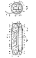
- the pneumatic tube can shown, which is described in the following in particular in connection with its use for pneumatic tube transport of paper and hard money, consists in the usual way of a tubular tube 1, at the ends of which head pieces 2 are mounted, the design of which is described in more detail below.
- the bush is, as usual, equipped with two sealing rings 3, it can be equipped with the usual, not shown scanning, contact and number rings for controlling and monitoring the desired path. (In the example of the use of the can described below, the control and monitoring of the path of the can take place in a different way.)
- a belt conveyor with two conveyor belts 4 and 5, which consist of a material that is related to paper money has a large static friction, such as the material commercially available under the brand name "Habasit belt".
- the working strands 6 and 7 of the conveyor belts 4 and 5 run in the longitudinal direction of the bush.
- the deflection drums 8 and 9 of the two conveyor belts 4 and 5 run closely one above the other, they can be driven at the same speed in corresponding directions - as explained further below - in order to pass through flat goods, for example paper money, a bundle of paper money, securities or other documents, which are fed to the bushing on the end face
- flat goods for example paper money, a bundle of paper money, securities or other documents
- the deflection drums 8 and 9 of the two conveyor belts 4 and 5 form a pair of drums 8, 9 at each end of the belt conveyor, which is arranged in one of the head pieces 2, so that the belt conveyor extends practically over the entire length of the sleeve.
- a slot-shaped opening 10 which is tapered in a funnel shape to the gap of the drum pair 8, 9 is formed.
- the drums 8 are each supported on a rocker 11 which is loaded by a spring (not shown) in the direction of the other drum 9, so that the gap between the drums 8 and 9 automatically adapts to the thickness of the flat material.
- the ends of the shafts 12 of the other drum 9 are each equipped with a link 13 of a releasable, in the example form-fitting, shaft coupling so that the belt conveyor is coupled with a drive device equipped with a corresponding coupling member and to be provided in both the transmitting and receiving stations and in one station for pulling flat goods into the can and in another station for pushing out the goods.
- the coupling members 13 are arranged in recesses 14 of the sleeve tube 1 so that they do not interfere with the running of the sleeve in the driving tubes of the pneumatic tube system and their position cannot be influenced.
- a chamber 15 for lumpy goods for example hard cash
- a hinged lid 17 which can be closed by a detachable cover (not shown) ten) locking device is held in its closed position, in which it forms part of the sleeve tube 1.
- the hinged cover 17 can be pivoted about an axis running along a sleeve tube jacket line and is provided with cams 18.
- the cams 18 slide on the inside of the tube wall in order to keep the lid 17 reliably closed in addition to being locked by the locking device.
- the wall 19 of the chamber 15 delimits the chamber space from the space occupied by the belt conveyor.
- the chamber floor 20 is at a small distance from the working section 6, and the empty section 21 of the conveyor belt 4 is guided through detour rollers 22 in a detour that circumvents the chamber between the chamber floor 20 and the working section 6.
- the detour rollers 22 are resiliently mounted so that they keep the conveyor belt 4 taut when one or both rockers give in to adapt the gap between the drums 8, 9 to the thickness of, for example, a bundle of paper money, the detour length changing.
- the working strands 6 and 7 also do not run in the middle of the sleeve cross section, but are offset with respect to the center of the sleeve cross section in the direction pointing away from the chamber 15.
- the width of the conveyor belts 4 and 5 is dimensioned such that the edges of the working strands in the conveyor plane are at a distance from the inside of the sleeve tube which is somewhat larger than the conveyor belt width, and the slot-shaped opening 10 which is funnel-shaped outwards is only straight in the region of the conveyor belt width , in addition to the level of the chamber floor, so that paper money (or other documents), the width of which is greater than the tendon lying in the plane of the working strands 6 and 7 of the clear cross-section of the sleeve tube 1, is inserted into the sleeve in the arched state and held therein, like the bundle of paper money 23 in FIG Supported (not shown) guide surface, which is provided in the sleeve and to the corresponding edge at the inner end of the slot-shaped opening. connects.
- the sleeve has a marking (not shown) on the sleeve tube which is scanned in a sleeve holding device of the pneumatic tube stations by a scanning device which controls a rotary drive which rotates the sleeve about its longitudinal axis in order to rotate the sleeve into a position in which the chamber opening 16 for filling the chamber above or for emptying below.
- the opening 10 is provided on each of the two end faces, so that the bushing on each end face is e.g. can be loaded and unloaded with paper money.
- the sleeve can also be provided with the opening 10 on only one end face.
- a pneumatic tube can is provided for each counter.
- an empty can (which either brought previously paid money to the counter or returned automatically after a money transfer to the safe or came back after a control command from the counter official) is held in a holding device in such a way that it is freely accessible at one end.
- a rotary drive for the sleeve is provided on the holding device, which has a scanning device which scans the mark made on the sleeve circumference in order to stop when the opening 16 of the sleeve is at the top.
- a drive device arranged on the holding device for the belt conveyor is automatically coupled to one of the coupling members 13 and the locking device of the bushing cover 17 is released.
- the counter official counts the money received and gives the amount with the associated data (denomination, counter number, individual identifier for the official) to a data processing system, he fills hard cash received by the customer with the lid 17 opened by hand or automatically in the chamber 15 and now open at the top closes the lid 17 again, the locking device engaging.
- the light beam of a light barrier which runs directly in front of the opening 10 is interrupted and sets the drive device in motion, so that the belt conveyor pulls the bundle of paper money between the working strands 6 and 7 into the can. If the bundle of paper money leaves the light beam, the drive then continues to operate chend a conveyor line, which corresponds to the distance of the light beam from the gap between the drums 8 and 9 on the insertion side of the sleeve, and then stops. The clutch is then automatically disengaged and the sleeve is released for transport to a cash receipt point in the vault, which is assigned to the counter.
- the hard cash in the closed chamber 15 and the bundle of paper money are held firmly between the working strands 6, 7.
- the can runs into a holding device in which it is automatically rotated so that the opening 16 is at the bottom.
- the locking device of the lid 17 is released, so that the weight of the lid opens down and the cash falls out of the chamber 15 into a bowl from which a slide leads to a cash sorter and counter.
- the coupling member of a drive device arranged at the cash receiving point is coupled to one of the coupling members 13 and the drive device is driven to eject the paper money bundle until a light barrier, the light beam of which runs on the ejection side of the can, responds to the fact that the paper money bundle has left the can.
- the paper money emitted is sorted and counted by a machine.
- the counted hard and paper money amount is expediently given to the data processing system. This checks whether it corresponds to the amount specified by the counter official and sends a corresponding signal to the counter.
- the counter clerk specifies the desired amount, the desired denomination and other data for spending money the data processing system.
- a cash dispenser assigned to the counter is controlled in the vault, which simultaneously fills hard and paper money into the can.
- the bush is released for transport to the counter. It is emptied at the counter as described for emptying in the vault, with the difference that smaller amounts are usually counted by hand at the counter.
- the bushing remains in the system permanently, it does not have to be removed, and the system can be designed in such a way that the bushings cannot be easily removed. Damage to the bushes and the stations due to incorrect manipulation can thus be ruled out. (Malfunctions due to operating errors can be prevented by circuitry measures taken by the control devices.) Finally, unauthorized access can be prevented by blocking every station, including the processes that can be triggered from it in the vault, in the idle state is and can only be unblocked with the help of a key or a scannable identification card of the counter clerk, the identification of which is registered in the data processing system together with the booking data in each process.
- the hard and paper money received at the counter can also be automatically counted and put into the can, whereby the amount is expediently displayed first after the counting and the money is only put into the can automatically after pressing an approval button.
Landscapes
- Physics & Mathematics (AREA)
- Engineering & Computer Science (AREA)
- Fluid Mechanics (AREA)
- Mechanical Engineering (AREA)
- Delivering By Means Of Belts And Rollers (AREA)
- Electric Cable Installation (AREA)
- External Artificial Organs (AREA)
- Pile Receivers (AREA)
- Basic Packing Technique (AREA)
Priority Applications (1)
| Application Number | Priority Date | Filing Date | Title |
|---|---|---|---|
| AT82102138T ATE11518T1 (de) | 1981-04-21 | 1982-03-17 | Rohrpostbuechse und rohrpoststation. |
Applications Claiming Priority (2)
| Application Number | Priority Date | Filing Date | Title |
|---|---|---|---|
| CH2590/81 | 1981-04-21 | ||
| CH259081 | 1981-04-21 |
Publications (2)
| Publication Number | Publication Date |
|---|---|
| EP0063691A1 true EP0063691A1 (fr) | 1982-11-03 |
| EP0063691B1 EP0063691B1 (fr) | 1985-01-30 |
Family
ID=4237199
Family Applications (1)
| Application Number | Title | Priority Date | Filing Date |
|---|---|---|---|
| EP82102138A Expired EP0063691B1 (fr) | 1981-04-21 | 1982-03-17 | Cartouche et station pour courrrier par tube |
Country Status (6)
| Country | Link |
|---|---|
| US (1) | US4470730A (fr) |
| EP (1) | EP0063691B1 (fr) |
| JP (1) | JPS6052050B2 (fr) |
| AT (1) | ATE11518T1 (fr) |
| CA (1) | CA1187465A (fr) |
| DE (1) | DE3262095D1 (fr) |
Cited By (2)
| Publication number | Priority date | Publication date | Assignee | Title |
|---|---|---|---|---|
| EP0343013A1 (fr) * | 1988-05-20 | 1989-11-23 | Tripmatic Limited | Systèmes de transfert pneumatique pour de l'argent comptant et cartouches pour utilisation dans de tels systèmes |
| CN105600450A (zh) * | 2009-10-11 | 2016-05-25 | 北京银融科技有限责任公司 | 一种交易系统工作站、工作方法及放入或取出物品的方法 |
Families Citing this family (19)
| Publication number | Priority date | Publication date | Assignee | Title |
|---|---|---|---|---|
| US4948303A (en) * | 1988-11-02 | 1990-08-14 | Washington Security Products, Inc. | Pneumatic tube carrier |
| AU3359197A (en) * | 1997-07-07 | 1999-02-08 | Kabushiki Kaisha Ace Denken | Game medium and banknote transfer system using air stream |
| AU3868797A (en) * | 1997-08-25 | 1999-03-16 | Kabushiki Kaisha Ace Denken | Bill conveyance system using air flow |
| US5980164A (en) * | 1998-02-03 | 1999-11-09 | Translogic Corporation | Pneumatic tube system carrier |
| CN1668519A (zh) * | 2002-06-04 | 2005-09-14 | 兰普森创意股份有限公司 | 安全系统 |
| US6672808B1 (en) * | 2002-06-17 | 2004-01-06 | Diebold, Incorporated | Pneumatic transfer terminal and method of operation |
| US6672807B1 (en) * | 2002-06-17 | 2004-01-06 | Diebold, Incorporated | Pneumatic transfer terminal and method of operation |
| WO2005108548A2 (fr) * | 2004-05-05 | 2005-11-17 | Translogic Corporation | Systemes de transport antimicrobiens |
| USD558258S1 (en) | 2006-03-07 | 2007-12-25 | Golston Product Solutions Company | Pneumatic carrier |
| USD546380S1 (en) | 2006-03-08 | 2007-07-10 | Golston Product Solutions Company | Pneumatic carrier with holder for writing implement |
| US7455481B1 (en) | 2006-03-08 | 2008-11-25 | Golston Product Solutions Company | Pneumatic carrier |
| AU308492S (en) | 2006-03-21 | 2006-08-08 | Lamson Concepts Pty Ltd | Carrier |
| GB0723795D0 (en) * | 2007-12-05 | 2008-01-16 | Air Tube Conveyors Ltd | Cash handling system |
| US8783436B2 (en) | 2010-01-29 | 2014-07-22 | Glory Ltd. | Money handling system and money handling method |
| GB2505627B (en) * | 2011-06-15 | 2015-08-19 | Airtube Technologies Ltd | Cash handling system |
| US9073708B2 (en) | 2012-08-30 | 2015-07-07 | Translogic Corporation | Sealed pneumatic carrier with slam-latch |
| US11030591B1 (en) | 2016-04-01 | 2021-06-08 | Wells Fargo Bank, N.A. | Money tracking robot systems and methods |
| US11148888B1 (en) | 2020-06-05 | 2021-10-19 | Translogic Corporation | Low force sealing pneumatic carrier |
| US11279571B1 (en) | 2021-02-09 | 2022-03-22 | Capital One Services, Llc | Instrument conveyance using a shuttle |
Citations (4)
| Publication number | Priority date | Publication date | Assignee | Title |
|---|---|---|---|---|
| CH261249A (de) * | 1946-06-03 | 1949-04-30 | Hirschi Fritz | Büchse für Rohrpostanlagen. |
| US3189297A (en) * | 1962-06-01 | 1965-06-15 | Mosler Safe Co | Pneumatic tube conveyer system |
| DE1531014A1 (de) * | 1966-06-28 | 1969-07-31 | Rejlers Ingenjoersbyra A B | Rohrpostanlage mit Einrichtungen zum selbsttaetigen Fuellen und Entleeren mehrerer umlaufender Rohrpostbuechsen |
| DE2703695A1 (de) * | 1976-02-10 | 1977-08-11 | Gao Ges Automation Org | Vorrichtung zur ausgabe von flachem foerdergut aus ausgabeautomaten |
Family Cites Families (4)
| Publication number | Priority date | Publication date | Assignee | Title |
|---|---|---|---|---|
| US3101892A (en) * | 1960-12-01 | 1963-08-27 | Nat Rejectors Gmbh | Bill-receiving cash boxes |
| SE401048B (sv) * | 1974-08-29 | 1978-04-17 | Lundblad Leif | For sedlar avsedd penningautomat |
| US4221376A (en) * | 1978-02-28 | 1980-09-09 | International Business Machines Corporation | Document cartridge and mounting apparatus |
| US4337864A (en) * | 1980-02-22 | 1982-07-06 | Docutel Corporation | Currency note dispensing system |
-
1982
- 1982-03-17 EP EP82102138A patent/EP0063691B1/fr not_active Expired
- 1982-03-17 AT AT82102138T patent/ATE11518T1/de not_active IP Right Cessation
- 1982-03-17 DE DE8282102138T patent/DE3262095D1/de not_active Expired
- 1982-04-01 US US06/364,248 patent/US4470730A/en not_active Expired - Fee Related
- 1982-04-08 CA CA000400734A patent/CA1187465A/fr not_active Expired
- 1982-04-19 JP JP57064081A patent/JPS6052050B2/ja not_active Expired
Patent Citations (4)
| Publication number | Priority date | Publication date | Assignee | Title |
|---|---|---|---|---|
| CH261249A (de) * | 1946-06-03 | 1949-04-30 | Hirschi Fritz | Büchse für Rohrpostanlagen. |
| US3189297A (en) * | 1962-06-01 | 1965-06-15 | Mosler Safe Co | Pneumatic tube conveyer system |
| DE1531014A1 (de) * | 1966-06-28 | 1969-07-31 | Rejlers Ingenjoersbyra A B | Rohrpostanlage mit Einrichtungen zum selbsttaetigen Fuellen und Entleeren mehrerer umlaufender Rohrpostbuechsen |
| DE2703695A1 (de) * | 1976-02-10 | 1977-08-11 | Gao Ges Automation Org | Vorrichtung zur ausgabe von flachem foerdergut aus ausgabeautomaten |
Non-Patent Citations (2)
| Title |
|---|
| GELDINSTITUTE, Nr. 2, 1981, J.F. WULPILLIER: "Die Automation der ZGV - eine bemerkenswerte Alternative" Seiten 49, 50 * |
| IBM TECHNICAL DISCLOSURE BULLETIN, Band 20, Nr. 8, Januar 1978, New York, R.L. HANSEN et al.: "Media Cartridge" Seiten 3303, 3304 * |
Cited By (4)
| Publication number | Priority date | Publication date | Assignee | Title |
|---|---|---|---|---|
| EP0343013A1 (fr) * | 1988-05-20 | 1989-11-23 | Tripmatic Limited | Systèmes de transfert pneumatique pour de l'argent comptant et cartouches pour utilisation dans de tels systèmes |
| WO1989011430A1 (fr) * | 1988-05-20 | 1989-11-30 | Tripmatic Limited | Systemes pneumatiques de transfert d'especes et boites utilisees dans ces systemes |
| CN105600450A (zh) * | 2009-10-11 | 2016-05-25 | 北京银融科技有限责任公司 | 一种交易系统工作站、工作方法及放入或取出物品的方法 |
| CN105600450B (zh) * | 2009-10-11 | 2018-03-20 | 北京银融科技有限责任公司 | 一种交易系统工作站、工作方法及放入或取出物品的方法 |
Also Published As
| Publication number | Publication date |
|---|---|
| JPS57184019A (en) | 1982-11-12 |
| ATE11518T1 (de) | 1985-02-15 |
| EP0063691B1 (fr) | 1985-01-30 |
| US4470730A (en) | 1984-09-11 |
| CA1187465A (fr) | 1985-05-21 |
| JPS6052050B2 (ja) | 1985-11-16 |
| DE3262095D1 (en) | 1985-03-14 |
Similar Documents
| Publication | Publication Date | Title |
|---|---|---|
| EP0063691B1 (fr) | Cartouche et station pour courrrier par tube | |
| DE3440136C2 (fr) | ||
| DE3325182C2 (fr) | ||
| EP1485883B1 (fr) | Dispositif de manipulation de billets de banque avec selecteur multi-chemin | |
| DE60203513T2 (de) | Vorrichtung zur annahme von bogen und wiederverwendungssystem | |
| DE3516384C2 (fr) | ||
| DE3216830C2 (de) | Banknoten-Ein/Ausgabe-Vorrichtung | |
| DE69737843T2 (de) | Banknotenbearbeitungsmaschine | |
| DE4331706C2 (de) | Banknotenannahme- und -ausgabevorrichtung | |
| DE68902578T2 (de) | Pneumatische bargeld-foerderanlagen und buechsen zur verwendung in derartigen anlagen. | |
| DE3324789A1 (de) | Automatisch arbeitende muenzenannahme- und -ausgabemaschine | |
| DE3743386A1 (de) | Maschine zur annahme und ausgabe von banknoten | |
| EP0199253B1 (fr) | Dispositif pour la réception, la vérification et le stockage de billets de banque | |
| WO1996026504A1 (fr) | Procede et dispositif de depot et de distribution surs de billets de banque | |
| DE3744815C2 (fr) | ||
| DE4123549C2 (fr) | ||
| DE69931695T2 (de) | Geldautomat mit front- und heck-beschickbaren Konfigurationen | |
| DE3312225A1 (de) | Vorrichtung zur zuruecknahme von an der ausgabestation eines automatischen bankschalters vorgelegten, aber nicht entnommenen papierbanknoten | |
| DE69711544T2 (de) | Vorrichtung zum vorläufigen Speichern von Geldscheinen | |
| DE3517848C2 (fr) | ||
| DE3321657C2 (fr) | ||
| DE69715270T2 (de) | Banknotenbearbeitungsmaschine | |
| EP1331185A2 (fr) | Dispositif pour aligner des objets sous forme de feuilles | |
| DE3431779C2 (fr) | ||
| DE69933732T2 (de) | Ausgabemechanismus für blattförmiges Gut |
Legal Events
| Date | Code | Title | Description |
|---|---|---|---|
| PUAI | Public reference made under article 153(3) epc to a published international application that has entered the european phase |
Free format text: ORIGINAL CODE: 0009012 |
|
| AK | Designated contracting states |
Designated state(s): AT BE CH DE FR GB IT LU NL SE |
|
| 17P | Request for examination filed |
Effective date: 19821215 |
|
| ITF | It: translation for a ep patent filed | ||
| GRAA | (expected) grant |
Free format text: ORIGINAL CODE: 0009210 |
|
| AK | Designated contracting states |
Designated state(s): AT BE CH DE FR GB IT LI LU NL SE |
|
| REF | Corresponds to: |
Ref document number: 11518 Country of ref document: AT Date of ref document: 19850215 Kind code of ref document: T |
|
| REF | Corresponds to: |
Ref document number: 3262095 Country of ref document: DE Date of ref document: 19850314 |
|
| PG25 | Lapsed in a contracting state [announced via postgrant information from national office to epo] |
Ref country code: LU Free format text: LAPSE BECAUSE OF NON-PAYMENT OF DUE FEES Effective date: 19850331 |
|
| ET | Fr: translation filed | ||
| PLBE | No opposition filed within time limit |
Free format text: ORIGINAL CODE: 0009261 |
|
| STAA | Information on the status of an ep patent application or granted ep patent |
Free format text: STATUS: NO OPPOSITION FILED WITHIN TIME LIMIT |
|
| 26N | No opposition filed | ||
| PGFP | Annual fee paid to national office [announced via postgrant information from national office to epo] |
Ref country code: LU Payment date: 19860411 Year of fee payment: 5 |
|
| PGFP | Annual fee paid to national office [announced via postgrant information from national office to epo] |
Ref country code: AT Payment date: 19870209 Year of fee payment: 6 |
|
| PGFP | Annual fee paid to national office [announced via postgrant information from national office to epo] |
Ref country code: NL Payment date: 19870331 Year of fee payment: 6 |
|
| PG25 | Lapsed in a contracting state [announced via postgrant information from national office to epo] |
Ref country code: GB Effective date: 19890317 Ref country code: AT Effective date: 19890317 |
|
| PG25 | Lapsed in a contracting state [announced via postgrant information from national office to epo] |
Ref country code: SE Effective date: 19890318 |
|
| PG25 | Lapsed in a contracting state [announced via postgrant information from national office to epo] |
Ref country code: LI Effective date: 19890331 Ref country code: CH Effective date: 19890331 Ref country code: BE Effective date: 19890331 |
|
| BERE | Be: lapsed |
Owner name: AUTELCA A.G. Effective date: 19890331 |
|
| PG25 | Lapsed in a contracting state [announced via postgrant information from national office to epo] |
Ref country code: NL Effective date: 19891001 |
|
| GBPC | Gb: european patent ceased through non-payment of renewal fee | ||
| NLV4 | Nl: lapsed or anulled due to non-payment of the annual fee | ||
| PG25 | Lapsed in a contracting state [announced via postgrant information from national office to epo] |
Ref country code: FR Free format text: LAPSE BECAUSE OF NON-PAYMENT OF DUE FEES Effective date: 19891130 |
|
| REG | Reference to a national code |
Ref country code: CH Ref legal event code: PL |
|
| PG25 | Lapsed in a contracting state [announced via postgrant information from national office to epo] |
Ref country code: DE Effective date: 19891201 |
|
| REG | Reference to a national code |
Ref country code: FR Ref legal event code: ST |
|
| EUG | Se: european patent has lapsed |
Ref document number: 82102138.3 Effective date: 19900124 |