EP0063695A1 - Procédé pour mésurer des temps de transit d'impulsions, des localisations de défauts et des atténuations dans des câbles et des guides d'ondes optiques - Google Patents
Procédé pour mésurer des temps de transit d'impulsions, des localisations de défauts et des atténuations dans des câbles et des guides d'ondes optiques Download PDFInfo
- Publication number
- EP0063695A1 EP0063695A1 EP82102487A EP82102487A EP0063695A1 EP 0063695 A1 EP0063695 A1 EP 0063695A1 EP 82102487 A EP82102487 A EP 82102487A EP 82102487 A EP82102487 A EP 82102487A EP 0063695 A1 EP0063695 A1 EP 0063695A1
- Authority
- EP
- European Patent Office
- Prior art keywords
- voltage
- pulse
- voltmeter
- calibrated
- generator
- Prior art date
- Legal status (The legal status is an assumption and is not a legal conclusion. Google has not performed a legal analysis and makes no representation as to the accuracy of the status listed.)
- Granted
Links
- 238000000034 method Methods 0.000 title claims abstract description 20
- 239000013307 optical fiber Substances 0.000 claims abstract description 8
- 238000013016 damping Methods 0.000 claims description 6
- 230000002123 temporal effect Effects 0.000 claims description 5
- 230000035945 sensitivity Effects 0.000 claims description 4
- 230000001960 triggered effect Effects 0.000 claims description 3
- 238000010276 construction Methods 0.000 abstract description 2
- 238000005259 measurement Methods 0.000 description 8
- 238000010586 diagram Methods 0.000 description 6
- 230000003287 optical effect Effects 0.000 description 5
- 238000013024 troubleshooting Methods 0.000 description 2
- 230000006978 adaptation Effects 0.000 description 1
- 230000010354 integration Effects 0.000 description 1
- 238000010079 rubber tapping Methods 0.000 description 1
Images

Classifications
-
- G—PHYSICS
- G01—MEASURING; TESTING
- G01M—TESTING STATIC OR DYNAMIC BALANCE OF MACHINES OR STRUCTURES; TESTING OF STRUCTURES OR APPARATUS, NOT OTHERWISE PROVIDED FOR
- G01M11/00—Testing of optical apparatus; Testing structures by optical methods not otherwise provided for
- G01M11/30—Testing of optical devices, constituted by fibre optics or optical waveguides
- G01M11/31—Testing of optical devices, constituted by fibre optics or optical waveguides with a light emitter and a light receiver being disposed at the same side of a fibre or waveguide end-face, e.g. reflectometers
- G01M11/3109—Reflectometers detecting the back-scattered light in the time-domain, e.g. OTDR
- G01M11/3145—Details of the optoelectronics or data analysis
Definitions
- the invention relates to a method for measuring pulse transit times, error locations and attenuations on cables and optical fibers, with a generator for voltage or light pulses that are fed into the test object, with a directional coupler, which directs the pulses reflected back from the test object to a detector.
- Such methods are predominantly carried out with reflectometers, a screen display being usually required for evaluating the measurement.
- a screen display being usually required for evaluating the measurement.
- complex electronic equipment is usually required in order to be able to recognize the desired signals on the screen.
- sample and hold circuits or similar integration methods are used here.
- An optical time-domain reflectometer for determining the attenuation of optical fibers consisting of a light source, a beam splitter, a detector, an amplifier, a signal conditioner and a display device and associated control units, in which the signal conditioner consists of a sample and hold circuit , with which the backscatter signal triggered periodically by a carrier pulse is sampled (DE-OS 28 37 981).
- the backscatter signals shown on the screen of such a reflectometer can be evaluated in many ways and allow conclusions to be drawn about a number of properties of the measured optical waveguide. In many cases, especially when troubleshooting, a small part of the information is sufficient.
- the invention is based on the object of specifying a method with which the fault location in a cable or in an optical waveguide can be determined with sufficient accuracy and with as little effort as possible without using a cathode ray tube.
- a sawtooth generator is triggered by each pulse of the generator, that the temporal value of the voltage output by the sawtooth generator is compared via a comparator with a first DC voltage that can be set in a defined manner, that this comparison with the time defined by the first DC voltage ⁇
- Generating a pulse serves that the output voltage of the detector is compared via a second comparator with a second DC voltage which can be set in a defined manner, that this second comparison is used to reject those signals which are reflected back, which exceed the set second voltage, and that the temporal coincidence of these rejected signals with the pulse defined in time by the first DC voltage in a gate circuit and indicated by an indicator.
- the advantages that can be achieved with the invention are, in particular, that commercially available and robust components can be used to carry out the method, that a cathode ray tube and the necessary high-voltage supply can be dispensed with, and that a measuring device operating according to the method of the invention can also be operated by trained personnel the harsh conditions on the construction site and when troubleshooting in the field.
- the definition of the first DC voltage is carried out by a first voltmeter, the display of which is calibrated in distance values.
- the distance indicator of the voltmeter is calibrated by a change in the sensitivity of the voltmeter that corresponds to the pulse velocity otherwise determined in the measurement object.
- This embodiment of the invention is particularly advantageous if a digital measuring device is used as the voltmeter, the sensitivity of which can be adjusted continuously and easily by entering digitized data.
- the distance indicator of the voltmeter is calibrated by a change in the amplitude of the sawtooth voltage of the sawtooth generator that corresponds to the pulse velocity otherwise determined in the test object.
- This configuration has the advantage that it offers a particularly cost-effective way of building a corresponding measuring device.
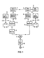
- the pulse generator 1 generates pulses, the course of which is shown in the first line. For the fault location in an optical waveguide, these are light pulses that are generated, for example, by a laser. They are directed to the test object 3 via a directional coupler 2.
- the directional coupler 2 consists of a beam splitter, preferably of a known light guide branch.
- Each pulse of the pulse generator 1 starts the sawtooth generator 4; whose output voltage U1 is shown in the second line.
- the temporal value of the sawtooth voltage U1 is compared in the first comparator 5 with an adjustable DC voltage U2.
- the output of the first comparator 5 tilts and starts the first monoflop 6, which gives a defined pulse to the gate circuit 7.
- the light pulse reflected back from the measurement object 3 passes through the directional coupler 2 to the detector 8, for example a photodiode with an amplifier connected behind it, the output voltage U3 of which is shown in the fifth line.
- This output voltage U3 is compared in the second comparator 9 with an adjustable second DC voltage U4, which is also shown in dashed lines in the 5th line.
- the second monoflop 10 starts and generates a display on the indicator 11, which can consist, for example, of an LED .
- the opening time of the gate circuit 7 can be shifted between 2 pulses of the generator 1 by changing the DC voltage 2 over the entire period.
- the gate circuit 7 is opened at a point in time at which a particularly powerful pulse is reflected back from the measurement object 3, as is typical, for example, for the end of an optical waveguide.
- Another Pulse at the output of the detector 8 indicates an error of approximately 2/3 the length of the optical fiber. It can be displayed on the indicator 11 by reducing the DC voltage U2.
- the level of the DC voltage U2 is a measure of the pulse transit time and thus of the location of the fault.
- the value of this DC voltage U2 can be determined using a calibrated voltage divider.
- the sensitivity of the voltmeter 12 can be varied continuously, which is easily possible when using a digital voltmeter.
- such an adaptation to the pulse speed in the test object 3 can also be achieved by the steepness of the sawtooth voltage U1.
- the amplitude of the reflected pulse just represented can be determined by changing the second DC voltage U4. In the simplest case, this can again be done by tapping this second DC voltage U4 via a calibrated voltage divider.
- the accuracy of this additional possibility of the method for damping measurement can be considerably improved if the value of the second direct voltage U4 is measured by a second digital voltmeter 13, the display of which is then expediently calibrated in damping values. In this way it is possible to carry out backscatter measurements and to follow the damping curve over the entire length of the measurement object 3.
Landscapes
- Physics & Mathematics (AREA)
- Engineering & Computer Science (AREA)
- Microelectronics & Electronic Packaging (AREA)
- Optics & Photonics (AREA)
- Chemical & Material Sciences (AREA)
- Analytical Chemistry (AREA)
- General Physics & Mathematics (AREA)
- Testing Of Optical Devices Or Fibers (AREA)
- Locating Faults (AREA)
- Optical Radar Systems And Details Thereof (AREA)
- Measurement Of Current Or Voltage (AREA)
Applications Claiming Priority (2)
| Application Number | Priority Date | Filing Date | Title |
|---|---|---|---|
| DE19813115200 DE3115200A1 (de) | 1981-04-15 | 1981-04-15 | Verfahren zur messung von impulslaufzeiten, fehlerorten und daempfung auf kabeln und lichtwellenleitern |
| DE3115200 | 1981-04-15 |
Publications (2)
| Publication Number | Publication Date |
|---|---|
| EP0063695A1 true EP0063695A1 (fr) | 1982-11-03 |
| EP0063695B1 EP0063695B1 (fr) | 1985-10-30 |
Family
ID=6130196
Family Applications (1)
| Application Number | Title | Priority Date | Filing Date |
|---|---|---|---|
| EP82102487A Expired EP0063695B1 (fr) | 1981-04-15 | 1982-03-25 | Procédé pour mésurer des temps de transit d'impulsions, des localisations de défauts et des atténuations dans des câbles et des guides d'ondes optiques |
Country Status (3)
| Country | Link |
|---|---|
| US (2) | US4527113A (fr) |
| EP (1) | EP0063695B1 (fr) |
| DE (1) | DE3115200A1 (fr) |
Cited By (4)
| Publication number | Priority date | Publication date | Assignee | Title |
|---|---|---|---|---|
| EP0075418B1 (fr) * | 1981-09-10 | 1986-02-26 | Patented Devices (Proprietary) Limited | Test de câble |
| EP0318043A1 (fr) * | 1987-11-27 | 1989-05-31 | Anritsu Corporation | OTDR avec fonction de mesure automatique des défauts de fibre optique |
| DE4143468C2 (de) * | 1990-10-30 | 2000-03-16 | Teradyne Inc | Schaltungsanordnung zur Erzeugung von Ausgangsimpulsen und Zeitsteuerschaltung für eine Schaltungsprüfvorrichtung |
| CN112290910A (zh) * | 2020-10-20 | 2021-01-29 | 云南电网有限责任公司临沧供电局 | 一种用于配变低压侧脉冲注入故障定位的倍压三角脉冲源电路 |
Families Citing this family (19)
| Publication number | Priority date | Publication date | Assignee | Title |
|---|---|---|---|---|
| DE3340428A1 (de) * | 1983-11-09 | 1985-05-23 | Wandel & Goltermann Gmbh & Co, 7412 Eningen | Verfahren und einrichtung zur ueberwachung eines optischen nachrichtenuebertragungssystems |
| SE442920B (sv) * | 1984-06-15 | 1986-02-03 | Asea Ab | Forfarande och anordning for detektering och lokalisering av ett felstelle pa en kraftledning |
| DE3429062A1 (de) * | 1984-08-07 | 1986-02-20 | Erwin Sick Gmbh Optik-Elektronik, 7808 Waldkirch | Vorrichtung zur messung der laufzeit von elektromagnetischen wellen |
| US4800265A (en) * | 1986-03-21 | 1989-01-24 | Amp Incorporated | Optical fiber continuity testing with pulsating optical test signal |
| US4797556A (en) * | 1986-03-21 | 1989-01-10 | Amp Incorporated | Optical continuity testing apparatus with pulsating transmitter |
| DE3614850A1 (de) * | 1986-05-02 | 1987-11-05 | Honeywell Regelsysteme Gmbh | Verfahren zur ermittlung des abstandes eines objektes und schaltungsanordnung zur durchfuehrung des verfahrens |
| FR2628525B1 (fr) * | 1988-03-14 | 1991-01-04 | Gaz De France | Procede et dispositif de lecture automatique d'un compteur de fluide a minuterie mecanique |
| US4958926A (en) * | 1988-10-31 | 1990-09-25 | Reliance Comm/Tec Corporation | Closed loop control system for laser |
| US4996654A (en) * | 1988-12-22 | 1991-02-26 | Tektronix, Inc. | Method of displaying acquired data |
| US4940892A (en) * | 1989-04-05 | 1990-07-10 | Amp Incorporated | Optical discontinuity monitor system |
| US5155439A (en) * | 1989-12-12 | 1992-10-13 | Tektronix, Inc. | Method of detecting and characterizing anomalies in a propagative medium |
| GB2242324B (en) * | 1990-03-22 | 1993-09-22 | Stc Plc | Fault location. |
| US5264796A (en) * | 1990-04-03 | 1993-11-23 | Ford Motor Company | Fault detection and isolation in automotive wiring harness including dedicated test line |
| US5268644A (en) * | 1990-04-03 | 1993-12-07 | Ford Motor Company | Fault detection and isolation in automotive wiring harness by time-domain reflectometry |
| DE4031668B4 (de) * | 1990-10-05 | 2006-02-02 | Carl Zeiss | Verfahren zur elektrooptischen Entfernungsmessung |
| US5457990A (en) * | 1991-12-03 | 1995-10-17 | Cambridge Consultants Limited | Method and apparatus for determining a fluid level in the vicinity of a transmission line |
| DE19518294C1 (de) * | 1995-05-18 | 1996-10-02 | Bosch Gmbh Robert | Optische Verstärkeranordnung |
| DE19830738B4 (de) * | 1998-07-09 | 2007-12-06 | Seba-Dynatronic Mess- Und Ortungstechnik Gmbh | Vorrichtung zur richtungsabhängigen Fehlerortung oder Nachrichtenübertragung auf Niederspannungsnetzen |
| CN109613344A (zh) * | 2018-12-12 | 2019-04-12 | 云南电网有限责任公司电力科学研究院 | 一种记录雷电伏秒特性方法及装置 |
Citations (6)
| Publication number | Priority date | Publication date | Assignee | Title |
|---|---|---|---|---|
| DE2656911A1 (de) * | 1975-12-24 | 1977-08-18 | Rasmussen As E | Anordnung zur lokalisierung einer stelle entlang eines elektrischen leiters, an der eine impedanzaenderung, wie ein bruch bzw. eine unterbrechung oder ein kurzschluss aufgetreten ist |
| DE2620357A1 (de) * | 1976-05-06 | 1977-11-17 | Aeg Telefunken Kabelwerke | Daempfungsmessung in lichtleitern |
| DE2727392B1 (de) * | 1977-06-18 | 1978-06-29 | Felten & Guilleaume Carlswerk | Verfahren zur digitalen Messung von Impulslaufzeiten und Kabellaengen |
| DE2837981A1 (de) * | 1978-08-31 | 1980-03-06 | Felten & Guilleaume Carlswerk | Optisches zeitbereichs-reflektometer zur bestimmung der daempfung von lichtleitfasern |
| US4203112A (en) * | 1977-05-24 | 1980-05-13 | Robert Bosch Gmbh | Method and system for increasing the distance which can be unambiguously measured by a radar system |
| DE2904703A1 (de) * | 1979-02-08 | 1980-08-28 | Felten & Guilleaume Carlswerk | Verfahren zur daempfungsmessung an lichtleitfasern |
Family Cites Families (9)
| Publication number | Priority date | Publication date | Assignee | Title |
|---|---|---|---|---|
| US3008137A (en) * | 1957-06-17 | 1961-11-07 | Sperry Rand Corp | Interval measuring apparatus |
| DE1219585B (de) * | 1961-12-20 | 1966-06-23 | Siemens Ag | Anordnung zum Ermitteln von Fehler- oder Inhomogenitaetsstellen elektrischer Leitungen |
| DE2024012C3 (de) * | 1969-05-21 | 1974-02-14 | Wsesojusnyj Nautschno-Issledowatelskij Institut Elektroenergetiki, Moskau | Vorrichtung zur Fehlerortung an Leitungen bzw. Kabeln mittels Impulsortung |
| US3668529A (en) * | 1971-01-11 | 1972-06-06 | Honeywell Inc | Measuring closely spaced pulses using time expansion |
| US3853005A (en) * | 1973-08-29 | 1974-12-10 | Measurand Syst | Interface measuring apparatus |
| FR2280072A1 (fr) * | 1974-07-26 | 1976-02-20 | Douillie Remy | Procede et equipement de mesure permettant de localiser une cassure sur un cable optique |
| DE2739880C2 (de) * | 1977-09-05 | 1985-04-18 | Philips Kommunikations Industrie AG, 8500 Nürnberg | Vorrichtung zur Fehlerortbestimmung in Lichtleitfasern oder Lichtleitfaserkabeln |
| DE2809154C3 (de) * | 1978-03-03 | 1980-09-04 | Felten & Guilleaume Carlswerk Ag, 5000 Koeln | Verfahren zur ungefähren Messung von Dampfungsverläufen an Vierpolen |
| DE3008821A1 (de) * | 1980-03-06 | 1981-09-10 | Siemens AG, 1000 Berlin und 8000 München | Auswertevorrichtung fuer ein optisches impulsreflektometer |
-
1981
- 1981-04-15 DE DE19813115200 patent/DE3115200A1/de active Granted
-
1982
- 1982-03-09 US US06/356,479 patent/US4527113A/en not_active Expired - Fee Related
- 1982-03-25 EP EP82102487A patent/EP0063695B1/fr not_active Expired
-
1985
- 1985-01-24 US US06/682,142 patent/US4606632A/en not_active Expired - Fee Related
Patent Citations (6)
| Publication number | Priority date | Publication date | Assignee | Title |
|---|---|---|---|---|
| DE2656911A1 (de) * | 1975-12-24 | 1977-08-18 | Rasmussen As E | Anordnung zur lokalisierung einer stelle entlang eines elektrischen leiters, an der eine impedanzaenderung, wie ein bruch bzw. eine unterbrechung oder ein kurzschluss aufgetreten ist |
| DE2620357A1 (de) * | 1976-05-06 | 1977-11-17 | Aeg Telefunken Kabelwerke | Daempfungsmessung in lichtleitern |
| US4203112A (en) * | 1977-05-24 | 1980-05-13 | Robert Bosch Gmbh | Method and system for increasing the distance which can be unambiguously measured by a radar system |
| DE2727392B1 (de) * | 1977-06-18 | 1978-06-29 | Felten & Guilleaume Carlswerk | Verfahren zur digitalen Messung von Impulslaufzeiten und Kabellaengen |
| DE2837981A1 (de) * | 1978-08-31 | 1980-03-06 | Felten & Guilleaume Carlswerk | Optisches zeitbereichs-reflektometer zur bestimmung der daempfung von lichtleitfasern |
| DE2904703A1 (de) * | 1979-02-08 | 1980-08-28 | Felten & Guilleaume Carlswerk | Verfahren zur daempfungsmessung an lichtleitfasern |
Cited By (5)
| Publication number | Priority date | Publication date | Assignee | Title |
|---|---|---|---|---|
| EP0075418B1 (fr) * | 1981-09-10 | 1986-02-26 | Patented Devices (Proprietary) Limited | Test de câble |
| EP0318043A1 (fr) * | 1987-11-27 | 1989-05-31 | Anritsu Corporation | OTDR avec fonction de mesure automatique des défauts de fibre optique |
| US4898463A (en) * | 1987-11-27 | 1990-02-06 | Anritsu Corporation | Optical time domain reflectometer with automatic measuring function of optical fiber defects |
| DE4143468C2 (de) * | 1990-10-30 | 2000-03-16 | Teradyne Inc | Schaltungsanordnung zur Erzeugung von Ausgangsimpulsen und Zeitsteuerschaltung für eine Schaltungsprüfvorrichtung |
| CN112290910A (zh) * | 2020-10-20 | 2021-01-29 | 云南电网有限责任公司临沧供电局 | 一种用于配变低压侧脉冲注入故障定位的倍压三角脉冲源电路 |
Also Published As
| Publication number | Publication date |
|---|---|
| DE3115200A1 (de) | 1983-02-03 |
| US4606632A (en) | 1986-08-19 |
| DE3115200C2 (fr) | 1989-12-14 |
| EP0063695B1 (fr) | 1985-10-30 |
| US4527113A (en) | 1985-07-02 |
Similar Documents
| Publication | Publication Date | Title |
|---|---|---|
| EP0063695B1 (fr) | Procédé pour mésurer des temps de transit d'impulsions, des localisations de défauts et des atténuations dans des câbles et des guides d'ondes optiques | |
| DE2512640A1 (de) | Verfahren und vorrichtung zur optischen ueberpruefung von zigarettenenden | |
| DE69309025T2 (de) | Optischer Zeitbereichreflektometer | |
| DE69737139T2 (de) | Verfahren und vorrichtung zur überwachung einer optischen faser mittels eines optischen zeitbereichsreflektometers | |
| DE69938578T2 (de) | Gerät zur Messung der Übersprechdämpfung zwischen optischen Fasern | |
| DE3008187A1 (de) | System zum ermitteln von fehlerstellen in einem optischen faseruebermittlungssystem | |
| DE2620357A1 (de) | Daempfungsmessung in lichtleitern | |
| DE68902224T2 (de) | Verfahren zum analysieren von optischen komponenten, optischen fasern oder netzwerken von optischen leitern durch zeitbereichsreflektometrie und zeitbereichsreflektometer. | |
| EP0012179A1 (fr) | Ajustage des extrémités de deux fibres optiques devant être connectées | |
| DE4220409C2 (de) | Verfahren zum Gewinnung von Anomalien einer zu untersuchenden Leitung | |
| DE2717412C3 (de) | Durchgangsprüfgerät für Lichtleitfasern | |
| DE19507809C2 (de) | Meßverfahren zur Erfassung pulsförmiger Störgrößen | |
| DE2904703A1 (de) | Verfahren zur daempfungsmessung an lichtleitfasern | |
| DE19928940A1 (de) | Verfahren zum Messen der Signalqualität eines optischen Datensignals | |
| DE3837591C2 (fr) | ||
| DE4425551A1 (de) | Meßgerät zum Messen des Verlaufs der charakteristischen Impedanz entlang einem Kabel | |
| DE3008821A1 (de) | Auswertevorrichtung fuer ein optisches impulsreflektometer | |
| EP0109079B1 (fr) | Méthode pour localiser des défauts de câble et dispositif pour sa mise en oeuvre | |
| DE4438415C2 (de) | Optisches Reflektometer | |
| EP0281795A1 (fr) | Procédé pour balayer un signal électrique variable dans le temps et dispositif pour sa mise en oeuvre et application d'un tel procédé | |
| DE2644157A1 (de) | Geraet zur lokalisierung von fehlerstellen in elektrischen kabeln | |
| DE2744219C3 (de) | Vorrichtung zur zerstörungsfreien Untersuchung von Lichtwellenleitern | |
| DE3409310C2 (fr) | ||
| EP0150268A2 (fr) | Dispositif de mesure pour déterminer la présence de fissures | |
| DE3525314A1 (de) | Messeinrichtung zur erfassung von messgroessen mittels optischer sensoren |
Legal Events
| Date | Code | Title | Description |
|---|---|---|---|
| PUAI | Public reference made under article 153(3) epc to a published international application that has entered the european phase |
Free format text: ORIGINAL CODE: 0009012 |
|
| AK | Designated contracting states |
Designated state(s): FR GB IT SE |
|
| 17P | Request for examination filed |
Effective date: 19830406 |
|
| ITF | It: translation for a ep patent filed | ||
| GRAA | (expected) grant |
Free format text: ORIGINAL CODE: 0009210 |
|
| AK | Designated contracting states |
Designated state(s): FR GB IT SE |
|
| ET | Fr: translation filed | ||
| PLBI | Opposition filed |
Free format text: ORIGINAL CODE: 0009260 |
|
| 26 | Opposition filed |
Opponent name: SEBA DYNATRONIC MESS- UND ORTUNGSTECHNIK GMBH Effective date: 19860724 |
|
| PLBM | Termination of opposition procedure: date of legal effect published |
Free format text: ORIGINAL CODE: 0009276 |
|
| STAA | Information on the status of an ep patent application or granted ep patent |
Free format text: STATUS: OPPOSITION PROCEDURE CLOSED |
|
| 27C | Opposition proceedings terminated |
Effective date: 19880730 |
|
| ITTA | It: last paid annual fee | ||
| PGFP | Annual fee paid to national office [announced via postgrant information from national office to epo] |
Ref country code: GB Payment date: 19930301 Year of fee payment: 12 |
|
| PGFP | Annual fee paid to national office [announced via postgrant information from national office to epo] |
Ref country code: FR Payment date: 19930324 Year of fee payment: 12 |
|
| PGFP | Annual fee paid to national office [announced via postgrant information from national office to epo] |
Ref country code: SE Payment date: 19930326 Year of fee payment: 12 |
|
| PG25 | Lapsed in a contracting state [announced via postgrant information from national office to epo] |
Ref country code: GB Effective date: 19940325 |
|
| PG25 | Lapsed in a contracting state [announced via postgrant information from national office to epo] |
Ref country code: SE Free format text: LAPSE BECAUSE OF NON-PAYMENT OF DUE FEES Effective date: 19940326 |
|
| GBPC | Gb: european patent ceased through non-payment of renewal fee |
Effective date: 19940325 |
|
| PG25 | Lapsed in a contracting state [announced via postgrant information from national office to epo] |
Ref country code: FR Effective date: 19941130 |
|
| REG | Reference to a national code |
Ref country code: FR Ref legal event code: ST |
|
| EUG | Se: european patent has lapsed |
Ref document number: 82102487.4 Effective date: 19941010 |