EP0063714B1 - Dispositif pour supporter le réservoir intérieur d'un réservoir cylindrique transportable, isolé et à vide - Google Patents
Dispositif pour supporter le réservoir intérieur d'un réservoir cylindrique transportable, isolé et à vide Download PDFInfo
- Publication number
- EP0063714B1 EP0063714B1 EP82102814A EP82102814A EP0063714B1 EP 0063714 B1 EP0063714 B1 EP 0063714B1 EP 82102814 A EP82102814 A EP 82102814A EP 82102814 A EP82102814 A EP 82102814A EP 0063714 B1 EP0063714 B1 EP 0063714B1
- Authority
- EP
- European Patent Office
- Prior art keywords
- container
- bearing
- resistant
- inner chamber
- bending
- Prior art date
- Legal status (The legal status is an assumption and is not a legal conclusion. Google has not performed a legal analysis and makes no representation as to the accuracy of the status listed.)
- Expired
Links
- 239000002184 metal Substances 0.000 claims abstract description 11
- 238000009835 boiling Methods 0.000 claims abstract description 4
- 239000007789 gas Substances 0.000 claims abstract description 4
- 238000005452 bending Methods 0.000 claims abstract 8
- 238000010521 absorption reaction Methods 0.000 claims abstract 2
- 230000003014 reinforcing effect Effects 0.000 claims description 3
- 238000010276 construction Methods 0.000 description 6
- 238000009413 insulation Methods 0.000 description 4
- 238000004519 manufacturing process Methods 0.000 description 4
- 238000005516 engineering process Methods 0.000 description 1
- 238000001704 evaporation Methods 0.000 description 1
- 230000008020 evaporation Effects 0.000 description 1
- 230000002787 reinforcement Effects 0.000 description 1
- 230000003068 static effect Effects 0.000 description 1
- 239000013589 supplement Substances 0.000 description 1
Images


Classifications
-
- F—MECHANICAL ENGINEERING; LIGHTING; HEATING; WEAPONS; BLASTING
- F17—STORING OR DISTRIBUTING GASES OR LIQUIDS
- F17C—VESSELS FOR CONTAINING OR STORING COMPRESSED, LIQUEFIED OR SOLIDIFIED GASES; FIXED-CAPACITY GAS-HOLDERS; FILLING VESSELS WITH, OR DISCHARGING FROM VESSELS, COMPRESSED, LIQUEFIED, OR SOLIDIFIED GASES
- F17C13/00—Details of vessels or of the filling or discharging of vessels
- F17C13/08—Mounting arrangements for vessels
- F17C13/083—Mounting arrangements for vessels for medium-sized mobile storage vessels, e.g. tank vehicles or railway tank vehicles
-
- F—MECHANICAL ENGINEERING; LIGHTING; HEATING; WEAPONS; BLASTING
- F17—STORING OR DISTRIBUTING GASES OR LIQUIDS
- F17C—VESSELS FOR CONTAINING OR STORING COMPRESSED, LIQUEFIED OR SOLIDIFIED GASES; FIXED-CAPACITY GAS-HOLDERS; FILLING VESSELS WITH, OR DISCHARGING FROM VESSELS, COMPRESSED, LIQUEFIED, OR SOLIDIFIED GASES
- F17C2203/00—Vessel construction, in particular walls or details thereof
- F17C2203/01—Reinforcing or suspension means
Definitions
- the invention relates to a device for storing the inner container of a vacuum-insulated cylindrical transport container for low-boiling liquefied gases in the outer container.
- the bearing elements should be as light as possible and designed so that the inner container can have the largest possible diameter. This is intended to keep the share of the payload in the permissible total container weight as large as possible. After all, the bearing elements should be poor thermal bridges so that they do not impair the vacuum insulation too much. This should keep evaporation losses low. These demands contradict each other. The goal of the container designers is therefore to create inner container bearings that represent an optimal compromise between the conflicting requirements.
- the national and international transport regulations for dangerous goods further limit the possibilities of the designer.
- the inner container storage must be designed so that twice the total weight in the direction of travel and in the vertical direction down and the single total weight is taken up and horizontally sideways.
- An additional limiting condition is that the shape of the bottoms and the cylindrical shape of the outer container must not be interrupted, since such interruptions reduce the payload disproportionately.
- a further limitation is given by the manufacturing costs, which technically preclude inner container storage from the outset.
- the invention has for its object to provide an inner container storage within the framework of the conditions mentioned, with which large payloads can be realized and the manufacturing costs can be reduced.
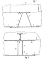
- the trapezoidal transverse segments of the fixed bearing form a shear-resistant connection between the inner and outer container, which widens towards the outer container in accordance with the torque curve, so that the longitudinal forces can be absorbed in the direction of travel. Since these longitudinal forces do not have to be absorbed by the floating bearing, the transverse segments there preferably have the shape of a rectangle in order to save weight.
- a T-shaped reinforcing ring is preferably each arranged on the inner surface of the inner container in the area of the fixed bearing and the floating bearing. Ropes which are guided in the area of the fixed bearing and floating bearing over the inner container and are fastened in abutments which are arranged on the inner surface of the outer container are preferred as elastic holders.
- An important advantage of the invention is that the distance in the area of the inner container storage between the inner and outer container can be considerably reduced compared to previous designs, without the thermal insulation and the stability being reduced. This results in a considerable increase in the payload.
- the design of the fixed and floating bearings is also so simple that the manufacturing costs are noticeably reduced.
- the vacuum-insulated transport container shown in FIG. 1 consists of the inner container 1 and the outer container 2.
- the undercarriage and the fastening of the outer container on the undercarriage are not shown.
- a vacuum is maintained between the inner container 1 and the outer container 2 for insulation.
- the inner container 1 is stored in the outer container 2 by means of a fixed bearing 3, a floating bearing 4 and ropes 5.
- the ropes 5 are fastened to abutments 6 which are arranged on the outer container 2.
- the fixed bearing 3 consists of a rigid sheet metal construction with a meandering cross section parallel to the circumference of the transport container.
- This rigid sheet metal construction essentially consists of transverse segments 7 arranged in the longitudinal direction of the transport container and segments 8 running in the circumferential direction.
- Another part of the fixed bearing 3 is the bearing shell 9, which is fastened on the support ring 10, which is welded onto the inner container 1.
- a corresponding support ring 11 is provided on the outer container 2.
- the floating bearing 4 is also designed according to the invention as a rigid sheet metal construction. In principle, it corresponds to the fixed bearing 3, that is to say essentially consists of transverse segments 12 and segments 13. Furthermore, support rings 14 and 15 are provided on the inner and outer container. The connection to the inner container 1 is made via a bearing shell 16, which, in contrast to the fixed bearing 3, is not rigidly connected to the inner container 1. The inner container 1 therefore slides on the bearing shell 16 by means of the support ring 14. The floating bearing 4 is therefore not stressed by temperature-related changes in the length of the inner container 1.
- a reinforcing ring 17 with a T-shaped cross section is provided in the area of the floating bearing 4.
- a corresponding reinforcement ring is also located in the area of the fixed bearing 3, but is not shown in the drawing.
- the upward forces are absorbed by ropes 5.
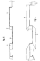
- Fig. 7 shows the attachment of the ropes 5 to the outer container in detail.
- the ropes 5 are guided over the inner container 1 and attached to abutments 6.
- the attachment and bracing is carried out by screw connections 18.
- the abutments 6 are welded to the inside of the outer container 2.
- the abutments 6 are reinforced by stiffening plates 19 and 20.
- the invention makes it possible to maintain the distance between the inner and outer containers of approximately 150 mm in the area of the inner container storage in a road transport container of customary size. This means a high proportion of the payload in the permissible total container weight. At the same time, the heat-conducting cross-section from the inner to the outer container is kept so small that the thermal insulation corresponds to the current state of the art.
- the shrinkage of the inner container in diameter when the temperature changes from the assembled state to the operating state is taken into account by appropriate pretensioning of the ropes 5, so that the ropes are tension-free in the operating state.
- the payload was increased by approx. 500 kg in one design. Since the rigid construction of the saddle bearings is relatively simple, it also saved around 200 hours in production.
Landscapes
- Engineering & Computer Science (AREA)
- Mechanical Engineering (AREA)
- General Engineering & Computer Science (AREA)
- Filling Or Discharging Of Gas Storage Vessels (AREA)
- Packages (AREA)
Claims (5)
Priority Applications (1)
| Application Number | Priority Date | Filing Date | Title |
|---|---|---|---|
| AT82102814T ATE6301T1 (de) | 1981-04-27 | 1982-04-02 | Vorrichtung zur lagerung des innenbehaelters eines vakuumisolierten zylindrischen transportbehaelters. |
Applications Claiming Priority (2)
| Application Number | Priority Date | Filing Date | Title |
|---|---|---|---|
| DE3116667A DE3116667C2 (de) | 1981-04-27 | 1981-04-27 | Vorrichtung zur Lagerung des Innenbehälters im Außenbehälter eines vakuumisolierten zylindrischen Transportbehälters |
| DE3116667 | 1981-04-27 |
Publications (2)
| Publication Number | Publication Date |
|---|---|
| EP0063714A1 EP0063714A1 (fr) | 1982-11-03 |
| EP0063714B1 true EP0063714B1 (fr) | 1984-02-15 |
Family
ID=6130907
Family Applications (1)
| Application Number | Title | Priority Date | Filing Date |
|---|---|---|---|
| EP82102814A Expired EP0063714B1 (fr) | 1981-04-27 | 1982-04-02 | Dispositif pour supporter le réservoir intérieur d'un réservoir cylindrique transportable, isolé et à vide |
Country Status (3)
| Country | Link |
|---|---|
| EP (1) | EP0063714B1 (fr) |
| AT (1) | ATE6301T1 (fr) |
| DE (1) | DE3116667C2 (fr) |
Families Citing this family (1)
| Publication number | Priority date | Publication date | Assignee | Title |
|---|---|---|---|---|
| US5533340A (en) * | 1994-04-12 | 1996-07-09 | Hydro-Quebec | Double-walled container for transporting and storing a liquified gas |
Family Cites Families (7)
| Publication number | Priority date | Publication date | Assignee | Title |
|---|---|---|---|---|
| US2814410A (en) * | 1954-06-24 | 1957-11-26 | Union Carbide Corp | Double wall tank |
| GB845275A (en) * | 1955-10-04 | 1960-08-17 | Air Prod Inc | Improvements in or relating to double-walled liquefied gas containers |
| DE1250289B (de) * | 1958-05-29 | 1967-09-14 | Chevron Research Company San Francisco, Calif (V St A) | Tragkonstruktion fur Flussig gastanks |
| BE585106A (fr) * | 1958-11-28 | |||
| GB899849A (en) * | 1961-02-15 | 1962-06-27 | Philip Leonard Spencer | Thermal insulating containers |
| US3481505A (en) * | 1967-05-24 | 1969-12-02 | Process Eng Inc | Support system for cryogenic containers (1) |
| DE2457264C2 (de) * | 1974-12-04 | 1977-01-13 | Linde Ag | Vakuumisolierter lager- oder transportbehaelter fuer tiefsiedende verfluessigte gase |
-
1981
- 1981-04-27 DE DE3116667A patent/DE3116667C2/de not_active Expired
-
1982
- 1982-04-02 EP EP82102814A patent/EP0063714B1/fr not_active Expired
- 1982-04-02 AT AT82102814T patent/ATE6301T1/de not_active IP Right Cessation
Also Published As
| Publication number | Publication date |
|---|---|
| EP0063714A1 (fr) | 1982-11-03 |
| ATE6301T1 (de) | 1984-03-15 |
| DE3116667C2 (de) | 1984-06-07 |
| DE3116667A1 (de) | 1982-11-04 |
Similar Documents
| Publication | Publication Date | Title |
|---|---|---|
| DE2646263C2 (de) | Tankbehälter zum Schienen-, Straßen-, Schiffstransport und zum Einsatz in Verladestationen | |
| DE3012938A1 (de) | Lagerung eines tankbehaelters in einem stuetzgeruest | |
| DE2457264C2 (de) | Vakuumisolierter lager- oder transportbehaelter fuer tiefsiedende verfluessigte gase | |
| DE3702057A1 (de) | Geruest mit verbindungsvorrichtungen | |
| DE8710906U1 (de) | Druckfester Tank | |
| DE1924462C3 (de) | Druckgefäß | |
| DE2805229A1 (de) | Stuetzanordnung fuer einen behaelter | |
| DE1195337B (de) | Behaelter zum Transport und zur Lagerung tiefsiedender verfluessigter Gase | |
| DE2554685A1 (de) | Behaelter fuer gasturbinentriebwerke, insbesondere gasturbinenstrahltriebwerke | |
| DE3116667C2 (de) | Vorrichtung zur Lagerung des Innenbehälters im Außenbehälter eines vakuumisolierten zylindrischen Transportbehälters | |
| AT370226B (de) | Verbundkonstruktion fuer behaelterwaende | |
| DE838597C (de) | Gefaess fuer hohe Innendruecke | |
| DE462361C (de) | Vorrichtung fuer den Bahntransport von fertig montierten und mit Versteifungskonstruktionen versehenen Grosstransformatoren | |
| DE2460742B2 (de) | Schalung zur Herstellung kegelförmiger Bauwerksteile | |
| DE2543729A1 (de) | Druckfester tankcontainer | |
| DE674648C (de) | Eiserner Grubenausbau mittels einzelstehender, ring- oder bogenfoermig gestalteter Profile | |
| DE2359114A1 (de) | Transporteinrichtung fuer radioaktives material | |
| DE2504123A1 (de) | Kernreaktordruckbehaelter | |
| DE3713152C1 (en) | Box-type telescoping crane jib | |
| DE3603354A1 (de) | Garten-pavillon | |
| DE7806797U1 (de) | Freitragender Transportcontainer für Flüssigkeiten | |
| CH329969A (de) | Tankwagen | |
| DE675922C (de) | Jauchefass | |
| AT214476B (de) | Luftseilbahnstütze | |
| DE1860188U (de) | Kabeltrommel. |
Legal Events
| Date | Code | Title | Description |
|---|---|---|---|
| PUAI | Public reference made under article 153(3) epc to a published international application that has entered the european phase |
Free format text: ORIGINAL CODE: 0009012 |
|
| AK | Designated contracting states |
Designated state(s): AT CH FR GB NL |
|
| 17P | Request for examination filed |
Effective date: 19821203 |
|
| GRAA | (expected) grant |
Free format text: ORIGINAL CODE: 0009210 |
|
| AK | Designated contracting states |
Designated state(s): AT CH FR GB LI NL |
|
| REF | Corresponds to: |
Ref document number: 6301 Country of ref document: AT Date of ref document: 19840315 Kind code of ref document: T |
|
| ET | Fr: translation filed | ||
| PGFP | Annual fee paid to national office [announced via postgrant information from national office to epo] |
Ref country code: FR Payment date: 19840504 Year of fee payment: 3 |
|
| PGFP | Annual fee paid to national office [announced via postgrant information from national office to epo] |
Ref country code: CH Payment date: 19840510 Year of fee payment: 3 |
|
| PLBE | No opposition filed within time limit |
Free format text: ORIGINAL CODE: 0009261 |
|
| STAA | Information on the status of an ep patent application or granted ep patent |
Free format text: STATUS: NO OPPOSITION FILED WITHIN TIME LIMIT |
|
| 26N | No opposition filed | ||
| PGFP | Annual fee paid to national office [announced via postgrant information from national office to epo] |
Ref country code: AT Payment date: 19860410 Year of fee payment: 5 |
|
| PGFP | Annual fee paid to national office [announced via postgrant information from national office to epo] |
Ref country code: NL Payment date: 19860430 Year of fee payment: 5 |
|
| PG25 | Lapsed in a contracting state [announced via postgrant information from national office to epo] |
Ref country code: AT Effective date: 19870402 |
|
| PG25 | Lapsed in a contracting state [announced via postgrant information from national office to epo] |
Ref country code: LI Effective date: 19870430 Ref country code: CH Effective date: 19870430 |
|
| PG25 | Lapsed in a contracting state [announced via postgrant information from national office to epo] |
Ref country code: NL Effective date: 19871101 |
|
| NLV4 | Nl: lapsed or anulled due to non-payment of the annual fee | ||
| PG25 | Lapsed in a contracting state [announced via postgrant information from national office to epo] |
Ref country code: FR Free format text: LAPSE BECAUSE OF NON-PAYMENT OF DUE FEES Effective date: 19871230 |
|
| GBPC | Gb: european patent ceased through non-payment of renewal fee | ||
| REG | Reference to a national code |
Ref country code: CH Ref legal event code: PL |
|
| REG | Reference to a national code |
Ref country code: FR Ref legal event code: ST |
|
| PG25 | Lapsed in a contracting state [announced via postgrant information from national office to epo] |
Ref country code: GB Effective date: 19881121 |